Table of Contents
Advertisement
Advertisement
Table of Contents

Summary of Contents for Blueworks BLSC
- Page 1 BLSC...
-
Page 2: Table Of Contents
WIRING ..................12 INSTALLATION CHECKLIST: ............ 16 INITIAL START UP: ..............16 OPERATION: ................17 GENERAL MAINTENANCE: ............21 WINTERIZING: ................23 HELPFUL NOTES: ..............24 TROUBLESHOOTING ............... 25 WARRANTY ................28 BLSC LABEL ................30 BLSC CELL REPLACEMENT LABEL ........31... -
Page 3: Important Safety Instructions
BLUEWORKS BLSC GENERATOR GENERATOR Installation and Operation Manual For BLSC IMPORTANT SAFETY INSTRUCTIONS When using electrical equipment, basic safety precautions should always be exercised, including the following: READ AND FOLLOW ALL INSTRUCTIONS Disconnect all AC power during installation. ... -
Page 4: Introduction
8 AWG US/ 6 AWG Canada. Introduction: The BLSC chlorine generator, by electrolysis, creates chlorine to sanitize your pool from the salt molecules (NaCL) in your water. A small electric charge is applied across a set of titanium plates inside the Electrolytic Cell. -
Page 5: System Overview
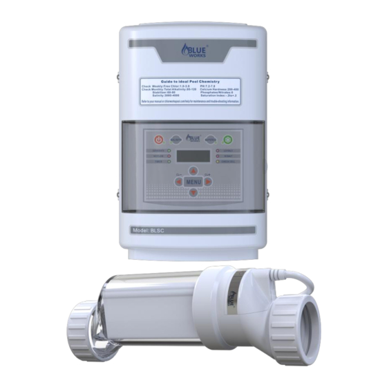
System Overview : There are three main Parts to BLSC system: the Control Unit, the Electrolytic Cell, and the Flow Switch. Control Unit: Supplies power to the cell and allows you customize the system's operation, in order to meet your pool's unique needs. -
Page 6: Water Chemistry
As with any pool, it is important that you maintain proper water chemistry of the pool water, including pH, alkaline content, and calcium levels. The only special requirement for BLSC is to maintain proper levels of salt and stabilizer. It is important to maintain these levels in order to prevent corrosion or scaling and to ensure maximum enjoyment of the pool. -
Page 7: Adding Salt/Salt Level
Adding Salt: IMPORTANT: Before adding salt, ALWAYS perform an independent water test to measure pre-existing salt levels. Use only evaporated, granulated, non-iodized salt (Sodium Chloride). The purer the salt (at least 99%), the better the life and performance of the Electrolytic Cell. DO NOT add chemicals or salt directly to the skimmer. - Page 8 Salt Levels: The system can work within a broad salinity range, from a minimum of 3000 ppm (parts per million), up to 4000 ppm. However, the ideal level for operation is about 3400 ppm. To achieve this level of salinity, add approximately 30 lbs of salt for every 1000 gallons of water (or 3.4 Kilograms of salt for every 1000 Liters).
- Page 9 POUNDS and (Kg) OF SALT NEEDED FOR 3400 PPM Gallons and (Liters) of Pool/Spa water Current 6,000 8,000 10,000 12,000 14,000 16,000 18,000 salt level (22,500) (30,000) (37,500) (45,000) (52,500) (60,000) (67,500) (82) (109) (136) (163) (190) (218) (245) (78) (103) (129) (154)
-
Page 10: Install Cell
Install cell: Install using the unions provided. Tighten by HAND for a watertight seal. For pool/spa combination systems with spillover, refer to the above Overview to allow chlorination for both the pool and spa during spillover but preventing over chlorination when operating the spa only. - Page 11 "inlet" side. If installed horizontally, ensure that the wire- side faces upwards. From end to end, the Cell with both Unions is approximately 15 ¾" in length; the typical gap required is 13 ¼". Refer to the overview diagram on page 4 for alternate configurations. For combined pool and spa systems with a spillover, allow chlorination for both the pool and spa during spillover but preventing possible over-chlorination when operating the spa only.
-
Page 12: Install Control
& efficient chlorine production. Install Control Unit: The BLSC control must be mounted a minimum of 5 ft. (2 meters) horizontal distance (or more if local codes require) from the pool/spa. The control is designed to mount vertically on a flat surface facing downward. -
Page 13: Wiring
operation, the Control Unit may be wired in to the pump's power source so that both turn on and off together, or energized continuously for use with variable speed pumps (Flow switch will control Cell power but lights will remain on). Notice: Do not operate unit until all salt is dissolved in pool water Wiring: Power must be shut off at the circuit breaker before performing any wiring. - Page 14 Wiring to Power Source: The Control Unit comes with an un-terminated Power Cord (AC Input) which is typically connected to an external timer, which will turn the pump and Control Unit on and off together. Have the Control Unit wired to the load side of the timer by a qualified person. See the following diagram for typical wiring.
- Page 15 In some parts of the United States and Canada, the Control Unit must be connected to a circuit protected by a Class A ground fault interrupter (GFI). Check local codes before connecting. At this point, this installation of your equipment is complete. If the water has not yet been prepared, then you are ready to begin adding salt and balancing your water chemistry.
- Page 16 system function. All service should only be attempted by a person with appropriate electrical skills, with all equipment disconnected from power. The is shipped from the factory with a 240 VAC configuration. If 120VAC is needed, move the internal jumpers as shown below. If unsure, seek professional advice. This set of terminal screws can be located inside of the Control Unit, and accessed by removing the four screws from the Control Unit's aluminum base.
-
Page 17: Installation Checklist
INSTALLATION CHECKLIST: □Cell Unions installed and glued into pipe work. □Threaded Collars on either side of the Cell are hand tight. □Flow Switch is installed and oriented properly. □Control Unit is affixed to wall and wired correctly. □Cell Cable and Flow Switch are connected to Control Unit. □You have checked and confirmed that Control Unit switches ON and OFF concurrently with filter pump, or is energized continuously for use with variable speed pump. -
Page 18: Operation
Operation: By familiarizing yourself with the operation of the BLSC, you can achieve the maximum performance for your pool. There are typically three factors that you can control which directly contribute to the amount of chlorine the will generate: 1) The chosen percentage of Chlorine Output, 2) Hours of pump run- time each day, 3) Water chemistry balance, including the amount of salt in the pool, and chemicals that minimize chlorine demand, such as stabilizer level in the water. - Page 19 Control Keypad CONTROL BUTTONS: 1)Power: Use this button to manually power the system on or off. 2)Salinity: Displays the average measurement of the most recent salinity levels in the pool water. The average is constantly being updated by real-time salinity readings. Notice: When first installed, this reading may display the last salinity readings taken at the factory.
- Page 20 4)Winter Mode: Reduces the chosen Chlorine Output setting by half, for periods of low chlorine demand during cool weather. 5)Chlorine Output: Use the left/right arrow buttons to raise/lower the system's power setting (the rate of chlorine production), in order to customize operation for your pool's needs.
- Page 21 or too cold for chlorine generation.This light may be off during rest periods of the system’s duty cycle • Super CL: Located on the Super CL Button, this LED is illuminated when the Super CL mode is active. • Remote: This part is controlled by a remote control system. •...
-
Page 22: General Maintenance
SAFETY n o ti ce : Using the Power Button to turn the system OFF does not remove power from the control box. Always disconnect power at the circuit breaker prior to attempting any service procedure. General Maintenance: To maintain maximum performance, it is recommended that you remove and visually inspect the cell at least every 3-4 months. - Page 23 illuminate the " Cell" light when such cleaning is necessary. With correct water chemistry, the Cell will typically only need cleaning once or twice a season. When removing the Cell for cleaning or replacement: Turn off all power, close return line valves if applicable. Unplug the cell cable connecting the Cell to the Control Unit.
-
Page 24: Winterizing
property damage. Winterizing: Very little chlorine is necessary at low temperatures. They will not produce chlorine at very cold temperatures, especially below 50° F. This feature extends the lifespan of the Cell. The Electrolytic Cell will be damaged by freezing water just as your pool plumbing would. In areas which experience severe or extended periods of freezing temperatures, be sure to drain all water from the pump, filter, supply and return lines before any freezing conditions occur. -
Page 25: Helpful Notes
HELPFUL NOTES: Proper operation of the chlorine generator can be easily verified by checking the lights on the control panel. However, if the pool remains cloudy, or the chlorine residual tests low, then the chlorine being produced is being lost due to high chlorine demand or improper water conditions To reduce the chlorine demand, check the pH and Stabilizer (Cyanuric Acid) reading. -
Page 26: Troubleshooting
24 hours, whichever comes first. 3. "No Flow" LED illuminated or flashing The BLSC has sensed a no flow condition and has stopped generating chlorine. Check that the flow switch is plugged into the connector on the bottom of the control unit and that the wire is not cut or damaged. - Page 27 Adjust pH levels to re-balance water. Warm pool water increases chlorine demand—increase Desired Level% or filter run time. Cold water (below 50F) can cause BLSC to stop generating (Generating LED flashing). Excessive scaling on cell. ...
- Page 28 on the algae treatment. It still may be a matter of days before the pool returns to “normal” and chlorine tests will show the desired 1-3ppm free chlorine reading. 9. “PCB” displayed and all 4 LEDs are illuminated. A possible printed circuit board fault has been detected. Call for service.
-
Page 29: Warranty
WARRANTY BLSC is warranted to be free from defects in materials and workmanship, under normal use and non-commercial application, for a period of THREE (5-7) years, per the schedule below. Proof of purchase is required. This limited warranty is extended exclusively to the original purchaser of the BLSC system and is non-transferable. - Page 30 Problems resulting from tampering, accident, electrical surges, abuse, neglect, unauthorized or unqualified repairs, product alteration, fire, flood, freeze damage, Acts of Nature or Acts of God. Damage or degrading of concrete, natural stone, wood or synthetic surfaces adjacent to the swimming pool or spa.
-
Page 31: Blsc Label
CONTROLS BACTERIA AND ALGAE Swimming pool (Spa) Waters Domestic OR Commercial A maximum of 230,000 litres of water can be treated with one BLSC unit. For swimming pools, a range of 1-3 ppm of free available chlorine must be maintained. -
Page 32: Blsc Cell Replacement Label
BLUEWORKS BLSC CELL REPLACEMENT Replacement electrode for the chlorine generating device BLSC This cell must only be used on this model of chlorine generating device. Read the Label, the Installation Manual and Operation Manual of the chlorine generating device BLSC before using.
Need help?
Do you have a question about the BLSC and is the answer not in the manual?
Questions and answers
How to set time in black model
How to set time