Table of Contents
Advertisement
Quick Links
Advertisement
Table of Contents

Subscribe to Our Youtube Channel
Related Manuals for Encom Harmony Series


Summary of Contents for Encom Harmony Series
- Page 1 H A R M O N Y G a t e w a y B a s i c Network Monitoring & Control User Manual...
- Page 2 Harmony Gateway Basic User Manual Harmony Gateway Basic User Manual V2.0.0 July 2020 Email: support@encomwireless.com Toll Free: 1-855-730-1122 Worldwide: (403) 230-1122 Web: www.encomwireless.com...
- Page 3 Harmony Gateway Basic User Manual...
-
Page 4: Table Of Contents
Harmony Gateway Basic User Manual TABLE OF CONTENTS WARNINGS AND PRECAUTIONS ................. 6 INTRODUCTION ......................7 THE HARMONY SYSTEM ....................... 7 HARMONY GATEWAY BASIC ....................7 OVERVIEW ..........................8 ANTENNAS WITH GATEWAY BASIC UNITS ................8 ANTENNAS COMPATIBLE WITH HARMONY GATEWAY BASIC UNITS ........8 SYSTEM TOPOLOGY .................... - Page 5 Harmony Gateway Basic User Manual...
-
Page 6: Warnings And Precautions
Harmony Gateway Basic User Manual WARNINGS AND PRECAUTIONS The following symbols indicate important safety warnings and precautions throughout this manual: WARNING indicates that serious bodily harm or death may result from failure to adhere to the precautions. CAUTION indicates that damage to equipment may result if the instructions are not followed. -
Page 7: Introduction
HARMONY GATEWAY BASIC The Harmony Gateway Basic is a compact master radio with functional expandability through connection to any Encom remote radio. The device allows you to monitor Harmony devices from a user-friendly front panel. A simple web-based interface lets you configure, control and check the status of the device. -
Page 8: Overview
Harmony Gateway Basic devices, designed with a reverse polarity TNC female antenna connector. NOTE: An antenna is not supplied with the unit. To order an antenna, please contact your local Encom Wireless dealer or email at sales@encomwireless.com. ANTENNAS COMPATIBLE WITH... -
Page 9: System Topology
Harmony Gateway Basic User Manual SYSTEM TOPOLOGY The primary topology that the Harmony Gateway Basic supports is Networked Mode. Networked Mode is used to set up for communication with STRATOS. This allows connected devices to be monitored and controlled anywhere an internet connection is available. -
Page 10: Led Indicators
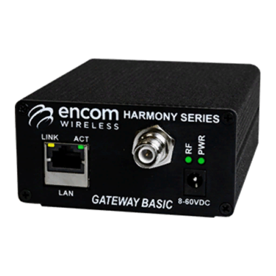
Harmony Gateway Basic User Manual LED INDICATORS There are four LED indicators on your Harmony Gateway Basic radio as follows: Ø PWR LED: Indicates the radio is powered ON. Ø RF LED: Indicates the radio is linked and communicating. There are two modes of behavior that the RF LED will have based on the connection between two HARMONY devices (Gateway E-Lite 450, Gateway Advanced,... -
Page 11: Installing Controlpak
Harmony Gateway Basic User Manual INSTALLING CONTROLPAK™ Before you can configure your Harmony Gateway After downloading the latest version of the ControlPAK™ software: Basic radio, you must first have the radio connected to your computer and ControlPAK™ must 1. Click Setup be installed on the same computer. -
Page 12: Configuring Your Harmony Gateway Basic
Harmony Gateway Basic User Manual CONFIGURING YOUR HARMONY GATEWAY BASIC The first step in using ControlPAK™ to configure your radio is to enter the correct configuration mode. There are three configuration mode options available from the main screen: • ETHERNET •... -
Page 13: Lan Connection And Startup
Harmony Gateway Basic User Manual LAN CONNECTION AND STARTUP NOTE: A straight through Ethernet cable is required to connect the Harmony Gateway Basic to a switch, a hub, or the computer on which ControlPAK™ is installed. On your desktop, double click the ControlPAK™ icon to start the software. Click on Ethernet, then click All Ethernet to start the system discovery process. -
Page 14: Lan Search
Harmony Gateway Basic User Manual LAN SEARCH To program a Gateway Basic radio, it must first be ‘discovered’ by ControlPAK. This means the Gateway Basic must be physically connected to your Ethernet network, or connected directly to the computer on which you are running ControlPAK. -
Page 15: Lan Search Tabs
Harmony Gateway Basic User Manual LAN SEARCH TABS Use the LAN Search tabs to find your radio based on IP, configure search parameters, and define a static IP for your radio as desired. Each of these tabs are defined as follows: Ø... -
Page 16: Connect List
Harmony Gateway Basic User Manual CONNECT LIST A Connect List file is used in instances where your Harmony Gateway Basic radios are part of a different IP network and need to be accessed. This list could include all or only specific radios in a network. Each Connect List is saved as a specific file. - Page 17 Harmony Gateway Basic User Manual MODIFY LIST The Modify List button allows you to create, edit and categorize lists of radios. § To modify an existing Connect List, select (click) your file from Connect List file and then click the Modify List button.
- Page 18 Harmony Gateway Basic User Manual Once a new Connect List file name is created, you can then add radios to the list from the Radios Found in LAN Search section. To add radios to your Connect List, select the newly created Connect List file from the File List section, select the radio in the Radios Found in LAN Search section and then click the double arrow ( ) button to the left of the Radios Found in LAN Search section.
-
Page 19: Configuring The Unit
Harmony Gateway Basic User Manual CONFIGURING THE UNIT The ENCOM Configuration window allows you to configure several different parameters on your Gateway Basic. This section will focus on the details of each parameter, which can be customized to best suit your system`s needs. -
Page 20: Basic Settings Tab
Pattern is set to 11. It is recommended to select a value that is different from the hop pattern of other Encom equipment. The primary hop pattern needs to match in each radio in the particular network for proper communication. -
Page 21: System Tab
Harmony Gateway Basic User Manual SYSTEM TAB In order for the Gateway Basic to communicate with other HARMONY devices on a particular network, a system needs to be created. During this step, the HARMONY devices that are communicating are added in. During the system setup, the schedule number that is to be used per device is to be added in during the creation of the system. - Page 22 Harmony Gateway Basic User Manual Enter a Description for the HARMONY device–this may be the location where the device is installed. Press the Apply button to add this entry to the list. Repeat these steps for each HARMONY device that is to be linked to your Gateway Basic.
-
Page 23: Alert Tab
Harmony Gateway Basic User Manual ALERT TAB In the Alert tab, you can configure your Gateway Basic to send out an alarm when an event has occurred (either involving a setting or system change, or a situation that requires maintenance). The different alarms and events that can be reported are shown below. -
Page 24: Snmp Tab
Harmony Gateway Basic User Manual SNMP TAB The SNMP tab allows your Gateway Basic to be configured for use in an SNMP-based network. Note that you must activate the Enable SNMP Operation option by clicking the checkbox to configure SNMP settings. The settings specific to SNMP operation are described below: •... -
Page 25: Protocol Tab
Harmony Gateway Basic User Manual PROTOCOL TAB The Protocol tab allows you to set up the communication method / protocol between your Gateway Basic and STRATOS I/O. The Protocol tab contains the following settings: • Gateway Protocol Mode – This setting controls the method of communication. o Polling –... -
Page 26: Calendar Tab
Harmony Gateway Basic User Manual CALENDAR TAB The Calendar tab allows you to set the clock of your Gateway Basic manually, use the clock of your connected PC to set up time, or connect to a Network Time Server to ensure that you constantly have the correct time set anywhere. -
Page 27: I/O Mapping Tab
The Gateway Basic unit supports the use of a hard-switch for wireless on/off control over the 900MHz network and/or over IP-based LAN network with all Encom HARMONY devices. If the Enable LAN I/O Mapping Forwarding check box is active (checked), the I/O mapping message from one system will transfer to other systems over the IP based LAN network. -
Page 28: Event Logs Tab
Harmony Gateway Basic User Manual EVENT LOGS TAB The Event Logs tab allows you to record data concerning the conditions and performance of your overall system. You can setup the Event Log to record general information, warnings and errors in the log entries, as well as what specific events get recorded. -
Page 29: Security Tab
Harmony Gateway Basic User Manual SECURITY TAB The Security Tab is where the user name and password for a radio can be configured. This ensures only authorized personnel are able to make changes to radio settings. -
Page 30: Appendix A: Upgrading/Downgrading Firmware
Harmony Gateway Basic User Manual APPENDIX A: UPGRADING/DOWNGRADING FIRMWARE 1. Connect to the Gateway Basic unit using ControlPAK™ and switch to the About tab. 2. Click the Firmware Upgrade button. 3. Accept the Firmware Upgrade License Agreement. 4. Read the warning message, check the box that says you have read and understand the warning and then click the Next button. -
Page 31: Appendix B: Rf Exposure
Harmony Gateway Basic User Manual APPENDIX B: RF EXPOSURE FCC Regulations allow up to 36 dBm effective radiated power (ERP). Therefore, the sum of the transmitted power (in dBm), the cabling loss and antenna gain cannot exceed 36 dBm. 1mW = 0 dBm Ø... -
Page 32: Appendix C: Declaration Of Conformity
Harmony Gateway Basic User Manual APPENDIX C: DECLARATION OF CONFORMITY This device complies with Part 15 of the rules. Operation is subject to the following two conditions: (1) This device may not cause harmful interference. (2) This device must accept any interference received, including interference that may cause undesired operation. - Page 33 Harmony Gateway Basic User Manual ENCOM Wireless provides field-proven, cost-effective wireless data solutions for municipal and industrial clients, with applications in the areas of: Intelligent Transportation Systems Public safety communications Municipal corporate security and IT networks Water and wastewater management...
Need help?
Do you have a question about the Harmony Series and is the answer not in the manual?
Questions and answers