Table of Contents
Advertisement
Quick Links
Oil Switches
Types NR, NRV
Maintenance Instructions
Type NR: Serial No. 309900 and after
Type NRV: Serieal No. 10500 and after
Figure 1.
Kyle
Type NR switch
®
WARNING: Do not energize this equipment out
of oil. Operation out of oil will result in flashovers
that will damage the equipment and may cause severe
personal injury.
CONTENTS:
Safety Information . . . . . . . . . . . . . . . . . . . . . . . . . . . .
Introduction . . . . . . . . . . . . . . . . . . . . . . . . . . . . . . . . . .
General Description . . . . . . . . . . . . . . . . . . . . . . . . . . .
Description of Operation . . . . . . . . . . . . . . . . . . . . . . .
Ratings and Specifications . . . . . . . . . . . . . . . . . . . . .
Maintenance . . . . . . . . . . . . . . . . . . . . . . . . . . . . . . . . .
Frequency of Maintenance . . . . . . . . . . . . . . . . . . . . .
Periodic Maintenance Inspection . . . . . . . . . . . . . . . .
. . . . . . . . . . . . . . . . . . . . . . . .
Electrical Operation . . . . . . . . . . . . . . . . . . . . . . . . . . .
Manual Operation . . . . . . . . . . . . . . . . . . . . . . . . . . . .
These instructions do not claim to cover all details or variations in the equipment, procedure, or process described, nor to provide
directions for meeting every contingency during installation, operation, or maintenance. When additional information is desired to
satisfy a problem not covered sufficiently for the user's purpose, please contact your Cooper Power Systems sales engineer.
November 1989
New Issue
Printed in USA
NOTICE: This document is also applicable to Cooper Power Systems
product serial numbers beginning with the characters CP57.
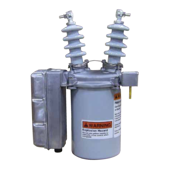
Figure 2.
89991KMA
Kyle
Type NRV switch
®
Oil Condition . . . . . . . . . . . . . . . . . . . . . . . . . . . . . . . . . . . 5
Insulation Level Withstand Tests . . . . . . . . . . . . . . . . . . . 5
Shop Repair Procedures . . . . . . . . . . . . . . . . . . . . . . . . . 6
Bushings . . . . . . . . . . . . . . . . . . . . . . . . . . . . . . . . . . . 6
Contacts . . . . . . . . . . . . . . . . . . . . . . . . . . . . . . . . . . . 6
Moving Contacts . . . . . . . . . . . . . . . . . . . . . . . . . . . 7
Stationary Contacts . . . . . . . . . . . . . . . . . . . . . . . . 7
Moving Contact Arm Assembiy . . . . . . . . . . . . . . . 8
2
Complete Contact Box Assembly . . . . . . . . . . . . . . 8
2
Actuator Mechanism . . . . . . . . . . . . . . . . . . . . . . . . . . 9
2
Selector and Holding Switches . . . . . . . . . . . . . . . . 9
3
Actuator Assembly Replacement . . . . . . . . . . . . . . 10
3
Greasing Recommendations . . . . . . . . . . . . . . . . . 11
4
Head Mechanism . . . . . . . . . . . . . . . . . . . . . . . . . . . . . . . . 11
4
Service Parts List . . . . . . . . . . . . . . . . . . . . . . . . . . . . . . . 12
4
4
Actuator and Housing Service Parts (Figure 24) . . . . . . . . 14
4
5
S260-20-8
Service Information
. . . . . . . . 12
89992KMA
1
Advertisement
Table of Contents

Related Manuals for Cooper Kyle NR Series


Summary of Contents for Cooper Kyle NR Series
-
Page 1: Table Of Contents
These instructions do not claim to cover all details or variations in the equipment, procedure, or process described, nor to provide directions for meeting every contingency during installation, operation, or maintenance. When additional information is desired to satisfy a problem not covered sufficiently for the user’s purpose, please contact your Cooper Power Systems sales engineer. November 1989... -
Page 2: Safety Information
Types NR, NRV Maintenance Instructions SAFETY INFORMATION Following is important safety information. For safe installation CAUTION: Follow all locally approved safety prac- and operation of this equipment, be sure to read and under- tices when lifting and mounting the equipment. Use stand all cautions and warnings. -
Page 3: Description Of Operation
S260-20-8 DESCRIPTlON OF OPERATION With the main switch contacts closed, energizing the opening circuit will operate the actuator motor to release a toggle which allows the preloaded opening springs to snap open the switch contacts and load the closing spring. It also drives the cam to position the selector switch for a closing operation and inter- rupts the opening circuit to stop the motor. -
Page 4: Maintenance
NOTE: Use only new, or like-new reconditioned transformer oil geous schedule. In no case should the service interval, between which conforms to the specifications in Cooper Power Systems periodic maintenance and inspection, extend beyond 1200 oper- Reference Data R280-90-1, “Oil Specifications and Test.”... -
Page 5: Manual Operation
S260-20-8 Manual Operation The switch may be manually opened and closed by operating the yellow handle under the sleet hood. NOTE: Manual operation does not affect the status of the electrically operated actuator. To electrically close a switch which has been manu- ally opened, the electrical open circuit must be first activated to change the status of the selector switch for a close operation. -
Page 6: Shop Repair Procedures
Types NR, NRV Maintenance Instructions TEST RESULTS: These high potential withstand tests provide information on the dielectric condition of the switch. 1. If the switch passes the closed-contacts test (Test 1) but fails the open-contacts test (Test 2) the cause is likely to be in the main contact assembly. -
Page 7: Moving Contacts
S260-20-8 MOVING CONTACTS Minor pitting can be smoothed with crocus cloth. If contacts show appreciable wear due to arc erosion, replace as follows: 1. Remove the round head screws and lockwashers that secure the moving contact bar to the contact arm. Remove the bar from the contact arm. -
Page 8: Moving Contact Arm Assembiy
Types NR, NRV Maintenance Instructions MOVING CONTACT ARM ASSEMBLY To replace the moving contact arm assembly proceed as follows: 1. Detach both opening springs from toggle link (Figure 12). 2. Pull back latch lever assembly and remove C-ring which secures the toggle link to the bell crank lever. NOTE: The latch assembly can be held back with a screwdriver as shown in Figure 13. -
Page 9: Actuator Mechanism
S260-20-8 4. To replace contact structure: A. Slip toggle link over bell crank lever and secure with C- ring. B. Attach contact structure to head casting with four hex head machine screws with lockwashers. C. Attach opening springs to toggle link. D. -
Page 10: Actuator Assembly Replacement
Types NR, NRV Maintenance Instructions 5. Connect wire lead(s) to terminal strip. Solder black lead(s) to common terminal of selector switch. 6. Operate cam electrically and adjust selector switch so con- tact actuation takes place relatively early on cam lobe, and that an over-travel (movement of operator arm after contact actuates) of approximately 3/64-inch is achieved. -
Page 11: Greasing Recommendations
S260-20-8 Figure 21. 891002KMA Components of head mechanism assembly. 7. To replace the latch lever assembly: A. Remove screws that secure the shaft retainers to the head casting. B. Lift out the latch lever assembly. C. When reassembling, slip the latch lever torsion spring and latch lever onto the latch lever shaft. -
Page 12: Service Parts List
To assure correct receipt of any part order, always include al. Further breakdown of listed assemblies is not recommended. switch type and serial number. Because of Cooper Power Sys- Dimensions of all common hardware parts have been care- tems’ continuous improvement policy, there may be instances fully checked so that they may be locally acquired. - Page 13 S260-20-8 Type HR-NRV Switches Service Parts (Figure 23) Item Qty. Item Qty. Description Catalog No. Description Catalog No. Assy. Assy Toggle spring KP40GH Bushing assembly, Type NR KA346NR3 Standard Bushing Shock absorber KP107NR Self-tapping screw, rd hd, 15” Creepage Bushing KA346NR4 Type F, 4-40 x 5/16, stl K751501104031 Z...
-
Page 14: Actuator And Housing Service Parts (Figure 24)
Types NR, NRV Maintenance Instructions Figure 24. Actuator and housing service parts. - Page 15 S260-20-8 Actuator and Housing Service Parts (Figure 24) Item Qty. Description Catalog No. Assy. Machine screw, Fil hd. #10-24 x 7/8 sst K999904250369A Cover KP323NR Gasket KP121NR KP2020A3 Split lockwasher, med 1/4 bronze K900830025000A Plain washer, #14S, brass K900525026056A Switch Assy. Holding KA741NR1 Selector...
- Page 16 1989 Cooper Industries, Inc. © Kyle is a registered trademark of Cooper Industries, Inc. ® P.O. Box 2850, Pittsburgh, WI 15230 11/89...
Need help?
Do you have a question about the Kyle NR Series and is the answer not in the manual?
Questions and answers