Table of Contents

Related Manuals for Zmorph VX


Summary of Contents for Zmorph VX
- Page 1 Product Manual ZMorph VX Mooltitool 3D Printer 3D printing worktable CNC PRO Plastic Extruder Milling Toolhead 3.00 mm CNC worktable Laser PRO Plastic Extruder Toolhead 1.75 mm Thick Paste Dual PRO Extruder Toolhead support.zmorph3d.com...
-
Page 2: Table Of Contents
3.2 Acceptance of warranty claim 3.3 Claim processing period 3.4 ZMorph’s liability 4. Certificates 5. What is ZMorph VX 6. How to use your ZMorph VX 3D printer 7. Sets 7.1 Types of sets and their content 8. Machine specification 8.1 Overview 8.2 Components... - Page 3 9. Setting up ZMorph VX 9.1 Location requirements 9.2 Safety features removal 9.3 Assembling the spool holder 9.4 First use 10. Maintenance 10.1 Toolheads maintenance 10.2 Changing worktable 10.3 Removing covers 10.4 Communication and File Delivery 11. Voxelizer 11.1 Installation and system requirements 11.2 Creating Voxelizer account...
- Page 4 13. CNC milling 13.1 CNC PRO Milling Toolhead 13.2 Materials compatible with CNC PRO toolhead 13.3 Material fixturing 13.4 Milling cutter fastening 13.5 CNC Milling file preparation 13.6 CNC Milling file starting (with calibration) 13.7 Tool changing process 13.8 CNC PRO Toolhead safety rules 14.
- Page 5 18. Firmware upgrades 18.1 General informations 18.2 Updating firmware 19. Help and support 19.1 Support request 19.2 Troubleshooting 19.3 Handy resources...
-
Page 6: Manual Guide
1. Manual guide 1.1 Introduction This manual describes the basic information about ZMorph VX, safety precautions, preparation for operations and basic maintenance. Read this manual guide carefully and understandably before operating the device for the first time. Ignorance of the in- structions may result in damage to the device, personal injury or reduced quality of the printed parts. -
Page 7: Health And Safety At Work
• When operating the printer, avoid situations that could cause burns or interfere with the proper functioning of the device. • Due to their size and specificity, ZMorph devices are not intended for use by children under 14 years of age and persons with reduced manual, motor and psychomotor skills. -
Page 8: Occupational Hygiene
• Handle the sharp accessories and tools included with the kit with special caution. 2.3 Electrical safety and risk ZMorph VX devices have been tested to comply with the Low Voltage Directive. In order to ensure maximum safety of use, including protection against short circuits, overloads, overvoltages and overheating of the product, the following provisions must be observed: •... -
Page 9: Safety And Mechanical Risks
2.6 Instructions for safe storage and transport • Store ZMorph VX devices at -10 to 40°C. • The storage place should be free from moisture and extreme weather conditions. - Page 10 Health and safety • When stored in original packaging, a maximum of 30 kg of weight can be placed on a single package. Recommendations for packing: • To transport the device, it is best to protect it with original protective foams; in case of lack of original foams, the device should be protected in such a way that free move- ment of the device in the transport packaging is not possible.
-
Page 11: Electromagnetic Compatibility (Emc)
• this device (system) is not sensitive to interference from other devices (systems), 2.8 Laser radiation The Laser PRO Toolhead supplied with ZMorph VX is a Class 4 laser with a power of 2.8 Watts and an emitted wavelength of 450 nm. Such lasers are extremely dangerous and emit visible and invisible radiation. -
Page 12: Manufacturer's Warranty And Liability
Manufacturer’s warranty and liability 3. Manufacturer’s warranty and liability ZMorph VX Multitool 3D Printer is designed to be modular and easy to service. In case of technical difficulty with any of the parts, it can be easily removed and shipped to man- ufacturer for maintenance. -
Page 13: Acceptance Of Warranty Claim
Zmorph; c) other interference in the product carried out by any person not authorized by Zmorph. 3.1.6 The warranty service does not apply to the actions stipulated in the User Guide which the user is obligated to perform on their own and at their own expense. -
Page 14: Zmorph's Liability
3.4.1 ZMorph is not required to modernize or modify the existing products after launch- ing their new versions. 3.4.2 ZMorph shall not be liable for any damages incurred by the Buyer due to the defect of the product, especially damages related to damage of other devices, loss of potential benefits or cost of replacement of the product. -
Page 15: Certificates
The technical documentation is kept at the Manufacturer address. Wrocław 01.10.2018r. ZMorph S.A. z siedzibą we Wrocławiu, zarejestrowana w Sądzie Rejonowym dla Wrocławia-Fabrycznej we Wrocławiu, IV Wydział Gospodarczy Krajowego Rejestru Sądowego pod nr KRS 0000724021, NIP 899-274-32-04, REGON 022111640. Kapitał zakładowy: 160 526,40 zł opłacony w całości. -
Page 16: What Is Zmorph Vx
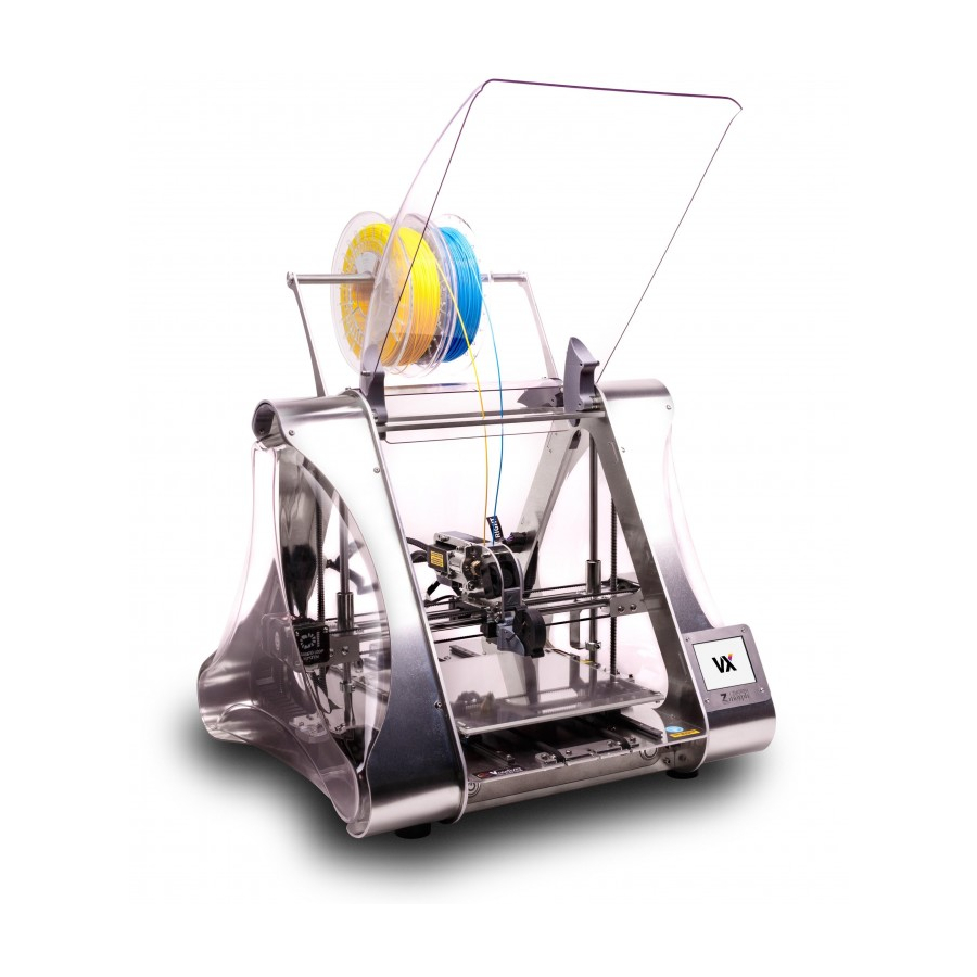
What is ZMorph VX. 5. What is ZMorph VX The ZMorph VX product is a multitool 3D printer. It has a system of interchangeable tool- heads, designed to perform 3D model prints in Fused Filament Fabrication (FFF) tech- nology, CNC milling, and laser engraving and cutting. ZMorph VX together with Voxelizer software provides a complete environment for moving 2D and 3D projects from monitor screen to reality. -
Page 17: How To Use Your Zmorph Vx 3D Printer
SD card. Alternatively, other software can be used to generate G-code files, but they do not fully take advantage of the capabilities of the ZMorph VX device and do not provide the sup- port for CNC and Laser toolheads. - Page 18 How to use • It is forbidden to cover the device with any material during operation. • It is forbidden to leave the device running unattended when working with the Laser PRO Toolhead. • It is forbidden to install or service the device by unqualified persons. •...
-
Page 19: Sets
7. Sets 7.1 Types of sets and their content What’s in the box: FULL SET PRINTING CUSTOM Dual Extruder Laser PRO Single 1.75 Extruder ZMorph VX CNC PRO Thick Paste 0,5 kg Extruder Spatula adjustable 10-13 mm CNC worktable wrench... -
Page 20: Machine Specification
Machine specification 8. Machine specification 8.1 Overview Front overview Spool holder (capacity up to 4x1kg spools) Toolhead Magnetic latches Left frame Right frame socket socket X-carriage Cooling fan Worktable touchscreen clamp release ON/OFF button Worktable Reset button... - Page 21 Machine specification Back overview Internal memory card USB socket Power cord socket Ethernet socket Nameplate...
-
Page 22: Components
8.2 Components • X-axis - double-toothed belt system driven by a stepper motor and stainless steel rods as guiding elements. Used for movement of the ZMorph VX toolhead. Must be period- ically lubricated to ensure a long life of the machine. - Page 23 Machine specification • X-carriage/Toolhead mount - element responsible for holding down toolhead, as well as automatic calibration. X-carriage has linear bearings mounted that slide on stain- less steel rods and is also a housing for a calibration element - strain gauge. Toolhead mounting is described in 10.1 part of this manual.
-
Page 24: Functionalities
• Platform leveling - to ensure proper first layer adhesion your printing bed must be lev- eled. ZMorph has developed special software and mechanical solution to make the leveling process easy and reliable. There are both automatic and manual calibration methods available. -
Page 25: Technical Specification
Machine specification 8.4 Technical specification Dimensions Machine dimensions without the spool holder 520 x 500 x 450 [mm] Machine dimensions with the spool holder 520 x 500 x 570 [mm] Package dimensions 600 x 600 x 570 [mm] Full Set weight 28.50 [kg] Machine weight 14.25 [kg]... - Page 26 Machine specification Laser cutting and engraving specifications Toolhead Laser PRO Laser spot size for 50mm 0.1 x 0.1 [mm] Laser spot size for 80 mm 0.1 x 0.18 [mm] Wavelength 450 [nm] Laser class Laser power 2.8 [W] Operating sound 40 [dB] Platform calibration Manual...
- Page 27 Machine specification Temperature specifications Nozzle temperature max. 250 [°C] Build plate temperature max. 125 [°C] Operating ambient temperature 15 ~ 30 [°C] Storage temperature -10 ~ 40 [°C] Electrical specifications 100 VAC ~ 4 A 50/60 Hz Power supply 240 VAC ~ 2 A 50/60 Hz Power consumption max.
-
Page 28: Setting Up Zmorph Vx
• Do not cover the machine with any materials during operation. • The machine should not be exposed to moisture. • The electrical installation of ZMorph VX requires it to be connected to a grounded wall outlet. • Do not use extension cords. -
Page 29: Safety Features Removal
Magnet- ic latches will keep the cover open. 9.3 Assembling the spool holder For a better experience with the ZMorph VX machine, it is recommended to assemble the dedicated spool holder. Prepare the spool holder Look at the back of Loosen the frame screws components and a 2.5... -
Page 30: First Use
Setting up ZMorph VX Loosen the screws to the Slide the spool holder in Tighten the screws. point where you can slide place. the spool holder. Take out the filament roll from the plastic bag and slide it on the bar. Put the bar with filament on the holders. - Page 31 Setting up ZMorph VX Take the calibration cable Connect the narrow end Choose "Maintenance". and connect the wider of the calibration cable to end to the RIGHT frame X-carriage B socket. socket. Choose "Calibrate". Choose "Auto 3-point". To ensure best calibra-...
-
Page 32: Maintenance
Maintenance 10. Maintenance 10.1 Toolheads maintenance Changing and mounting toolheads require 3 mm Allen key usage. It is included in the foam insert with accessories. Toolhead disassembly Select "Maintenance". Select "Change tool". Select "PARK TOOL", wait for positioning process to be finished. Disconnect the toolhead Disconnect the toolhead Use 3 mm Allen key to... - Page 33 Maintenance Mounting toolheads Each toolhead has similar mounting method. Find the bottom hooks While placing the tool- Gently mount new tool- placed on the back of the head be sure the hooks head placing it from the toolhead. are in the right place. back to the front in the X-carriage.
- Page 34 Maintenance Next steps depend on which toolhead will be used: Single Plastic Extruder 1.75 Dual PRO • Connect the LEFT cable to the LEFT • Connect the LEFT cable to the LEFT frame socket. frame socket and RIGHT cable to the •...
-
Page 35: Changing Worktable
Maintenance 10.2 Changing worktable Place toolhead in conve- Slide the table back- Disconnect the table nient position for remov- wards. plug. ing worktable. NOTE: The user can move the toolhead manually by disabling the motors by: • pressing the reset button, •... -
Page 36: Removing Covers
Maintenance Make sure that lever doesn’t block the table movement by pulling forward 10.3 Removing covers There are two types of covers: front and back covers side covers... - Page 37 Maintenance Front and back covers To remove front and back covers: Lift them up. Grab on both sides. Pull toward yourself. They are snapped via magnets so removing and attaching comes easily. The differences between front and back cover are shown in the picture below. Front cov- er has additional magnets that allow snapping in elevated position attached.
- Page 38 Maintenance Side covers To remove side covers: Find the two hooks Release the cover rear Pull out the cover rear blocking the covers. corner from the hooks corner from the machine by gently squeezing the frame. cover. Pull out the cover upper corner from the machine frame.
-
Page 39: Communication And File Delivery
Maintenance 10.4 Communication and File Delivery Delivery of files on SD card • Save a file you want to print to on SD card. • Insert a card on the right hand side of the display. NOTE: If the user inserted the external SD card the screen should jump forward to the 'Choose File' menu screen on the 'EXTERNAL’... - Page 40 Maintenance • Choose a folder with files from the external SD card: New project Choose file in external Choose file Connecting the machine via Ethernet • Connect Ethernet cable to the back of the machine and a computer. • The information about the IP address of the machine can be found in the INFO screen in the MAINTENANCE menu.
- Page 41 Maintenance • Provide the IP address in the web browser window. • A full interface for controlling the machine and files sharing will appear in the web browser. Connecting the machine via USB. • Connect the USB cable to the back of the machine and a computer. •...
-
Page 42: Voxelizer
Voxelizer 11. Voxelizer 11.1 Installation and system requirements Voxelizer can be downloaded from the website https://voxelizer.com/download. Once the download is finished, run the installation wizard and follow the instructions provided on the screen. Minimum system requirements: • Operating system: Windows 7 or higher, 64-bit or MacOS 10.13 or higher (Mac Mini 6.0 Late 2012 or later, other Apple devices 2014 or later) •... -
Page 43: License
Click the link to activate the account. 11.3 License The license for Voxelizer comes free for all ZMorph Owners. It is account-based: one printer provides one license which can be linked with the Voxelizer account. There are two ways to link the license: •... - Page 44 Voxelizer the fabrication process by specifying the used materials and other settings; during the third step instructions for the machine (G-code) are generated, previewed and exported. Taking the 3D printing workflow as an example, after selecting the tool in the welcome wizard, import a model in one of the different formats supported, for instance, an .STL.
- Page 45 G-code instructions and look for possible errors by using the Diagnostic tab. Clicking on the Save button results in saving the G-code: on a computer, SD card or directly on ZMorph VX Multitool 3D Printer.
-
Page 46: Presets
Voxelizer 11.5 Presets Voxelizer includes a set of tested presets for standard fabrication scenarios in all work- flows. The user can define his own presets to adapt the software to new materials and specific project requirements. Workflow Preset types 3d printing Filament, Durability, Support Laser cutting Material... - Page 47 Voxelizer The customized user presets can be added and modified in tabs dedicated to presets, e.g "Filament preset list". There are also other tabs signed by tooth gear icon responsible for durability and support structures settings.
- Page 48 Voxelizer To add a new preset, choose one of the existing presets and click the copy icon. The preset has been duplicated and can be modified depending on the needs. After editing preset parameters, the changes will save automatically. The preset will remain until its deleted.
-
Page 49: D Printing Workflow
Toolhead cable Heat break "A" plug Thermistor Heating block Nozzle Toolhead Specification: • Construction: High-quality 3 mm aluminium frame • Hot End: ZMorph interchangeable nozzle 1.75 mm • Temperature control: 1 thermistor • Temperature range: 0 - 250 ˚C degrees... - Page 50 Heating block Nozzle Specification: • Construction: High-quality 3 mm aluminium frame • Hot End: ZMorph interchangeable nozzle 3.0 mm • Temperature control: 1 thermistor • Temperature range: 0 - 250 ˚C degrees • Nozzle 0.3, 0.4 mm • Motor: Nema 17 stepper motor with planetary gear...
- Page 51 It’s perfect for manufacturing double-material prototypes, jigs and fixtures and other high-quality models from almost all materials available on the market as: ABS, M-ABS, PLA, HIPS, Flex, PVA, PET, ASA and others. Dual PRO 1.75 mm is included in VX Full Set machine sets. Default nozzle is 0.4 mm.
-
Page 52: Printing Materials
3D printing workflow • Temperature control: 2 thermistors • Temperature range: 0 – 250 ˚C • Nozzle: 0.4 mm • Motor: Nema 11 stepper motor with planetary gear x2 • Extrusion: Direct Drive • Work area: up to 235 x 250 x 165 mm •... -
Page 53: Loading The Filament
Take out the filament roll sticker on the filament from the plastic foil, re- roll. ZMorph VX package move moisture absorber. comes with PLA. - Page 54 3D printing workflow To preheat the extruder, follow these steps. Choose the "Mainte- Choose "Load Filament". Choose PARK TOOL, wait nance" from the LCD for the machine to posi- touchscreen menu. tion the toolhead. When done, choose "PLA" to preheat the material. NOTE: The "PREHEAT PLA"...
- Page 55 (full set). sticker on the filament Take out the filament roll. ZMorph VX package rolls from the plastic foil, comes with 0.5 kg white remove moisture absorb- and 0.5 kg silver PLA...
- Page 56 3D printing workflow To preheat the extruder, follow these steps. Choose the "Mainte- Choose "Load Filament". Choose PARK TOOL, wait nance" from the LCD for the machine to posi- touchscreen menu. tion the toolhead. When done, choose "PLA" to preheat the material. NOTE: The "PREHEAT PLA"...
- Page 57 3D printing workflow Push the filament down Insert the second fila- Tap the bottom arrow on until you feel it has been ment into the right side the screen to feed 80 mm grabbed by the extruder guide hole on top of the of the filament.
- Page 58 3D printing workflow 12.3 Removing the filament Single Plastic Extruder To preheat the extruder, follow these steps. Choose the "Mainte- Choose "Load Filament". Choose PARK TOOL, wait nance" from the LCD for the machine to posi- touchscreen menu. tion the toolhead. When done, choose "PLA"...
- Page 59 3D printing workflow Dual PRO Extruder To preheat the extruder, follow these steps. Choose the "Mainte- Choose "Load Filament". Choose PARK TOOL, wait nance" from the LCD for the machine to posi- touchscreen menu. tion the toolhead. When done, choose "PLA" to preheat the material.
-
Page 60: Material Exchanging
3D printing workflow 12.4 Material exchanging Single Plastic Extruder To preheat the extruder, follow these steps. Choose the "Mainte- Choose "Load Filament". Choose PARK TOOL, wait nance" from the LCD for the machine to posi- touchscreen menu. tion the toolhead. When done, choose "PLA"... - Page 61 3D printing workflow For any other materials Tap the "Left" gap in the Tap the needed tempera- than PLA and ABS, tem- "Target: column. ture on the keyboard, peratures needed to be then OK. set up manually. Tap the Custom Tem- perature button.
- Page 62 3D printing workflow Wait till extruder reaches Tap the LOAD/UNLOAD Tap the upper LEFT the proper temperature. menu. arrow on the screen to The yellow HEATING sign remove 80 mm of the will change colour from filament. At first, extruder yellow to green.
-
Page 63: Filament Replacement During Printing
3D printing workflow Tap the "Left" gap in the Tap the needed tempera- Since the Dual PRO "Target: column. ture on the keyboard, toolhead has one nozzle, then OK. the set up temperature adjusts for left and right filament. Wait the extrud- er to heat up. - Page 64 3D printing workflow Wait until the extruder Tap the "HEATING" menu Tap the "LOAD/UNLOAD" stops printing and lifts and check if the extruder menu. itself up. has the right tempera- ture. Tap the upper arrow on Insert new filament gen- Tap the bottom arrow the screen to remove 80 tly into the guide.
- Page 65 3D printing workflow Dual PRO Extruder This function allows you to change the filament during the printing process. The new filament must be of the same material as the new one (PLA/PLA) because the tempera- ture of the extruder will be the same as for the filament that was there before. Tap the "Settings"...
-
Page 66: Autocalibration
3D printing workflow Tap the bottom arrow Push the filament down Wait until the material on the screen to feed until you feel it has been flows out of the nozzle. 80 mm of the filament. grabbed by the extruder. Tap the feed button again Choose down arrow with if necessary. - Page 67 3D printing workflow Take the calibration ca- Connect the wider end to Connect the narrow end ble. The cable is included the RIGHT frame socket. of the calibration cable to in the box. X-carriage B socket. Choose "Maintenance". Choose "Calibrate". Choose "Auto 3-point".
- Page 68 After that the cess. calibration process ends. Look at printed lines Apply your choice. ZMorph VX calibration is and select the best one complete. on the screen. A correct line is the one that sticks to the table after gen-...
- Page 69 3D printing workflow NOTE: If none of the printed lines is proper, please follow these steps: Choose NONE option. Choose APPLY. Printer will ask which of the line is closest to the best result 1 or 5. Pick one and tap NEXT. The machine will prepare Select the best one Calibration completed.
- Page 70 3D printing workflow DUAL PRO Extruder NOTE: Before performing the automatic calibration make sure the worktable is clean and prepared. NOTE: See the toolhead changing process before mounting the Dual PRO extruder on the machine. NOTE: During the automatic calibration process the printer is heating up! Connect the LEFT cable Connect the extruder "A"...
- Page 71 3D printing workflow Use the arrow buttons Wait for the machine to Look at printed lines on the screen to feed the finish printing pattern. and select the best one material on both sides on the screen. A correct of the extruder until it line is the one that sticks start to pour out from the to the table after gen-...
- Page 72 3D printing workflow ZMorph VX calibration is Clean the bed. Your complete. machine is ready for your first print! NOTE: If none of the printed lines is proper, please follow these steps: Choose NONE option. Choose APPLY. Printer will ask which of the line is closest to the best result 1 or 5.
-
Page 73: Manual Calibration Process
3D printing workflow If after the second round of calibration the user still decides that none of the lines are accurate, the machine will show a warning screen and advise to repeat the auto- matic calibration process NOTE: If meeting calibration issues or autocalibration or to perform the manual calibration. -
Page 74: Calibration - Additional Functions
3D printing workflow Wait until the extruder Use arrows on the touch- When the nozzle is at the stabilizes itself on the screen to lower or raise correct height, choose right height. the extruder by 0.05 mm. 'Set new Z0' (Visual or paper verification). - Page 75 3D printing workflow Choose "Manual 3-point Wait until the extruder Clean the nozzle and calibration". reaches the calibration table from unnecessary position, on the left cen- material. tral part of the worktable. Take a small sheet of Set the nozzle at Z=0 for Use the arrows to set paper and place it be- the Point1: move the axis...
-
Page 76: Preparing The Worktable
3D printing workflow Manual 3-point calibra- tion process is finished! NOTE: Move the paper between the nozzle and the worktable surface, if the nozzle is too low, the paper won't move. If the nozzle is too high above the surface the paper sheet will be loose. -
Page 77: Files Preparation
3D printing workflow Apply a thin layer of an The table is ready for 3D adhesive agent to the printing. worktable. 12.10 Files preparation Single Plastic Extruder Launch Voxelizer Select the model of your printer, when done click the graphic representing machine. Co- lour of graphic will change to blue and new settings column will appear. - Page 78 3D printing workflow Choose Single 1.75 mm extruder Choose nozzle 0.3 mm. This nozzle is mounted in extruder as a default. Use an option "Remember my choice" to save chosen settings.
- Page 79 3D printing workflow Choose START. Import file by using one of marked buttons. Select an STL file. After importing the file, a toolbar will appear on the left that allows basic operations on the mesh model, such as: scaling (SCALE), scaling to specific dimensions (DIMENSION), rotating (ROTATE), and moving the model to specific position (MOVE).
- Page 80 3D printing workflow You can set values manually or use sliders. Set the model according to your preferences and click NEXT to voxelize the model. The second step of the file preparation is to set the printing parameters. There are 2 types of menus - global (placed to the left of the screen) and local (opened by clicking the right mouse button on the model).
- Page 81 3D printing workflow In the global menu you can set: a) Filament - defines a filament type that will be used in the project, e.g: PLA ZMorph, ABS ZMorph, PET ZMorph. Basing on the filament choose, Voxelizer will adapt print- ing settings. To see the details of the print settings, click the button SEE MORE or go to Filament preset list.
- Page 82 3D printing workflow c) Adaptive height - option to enable or disable the height of the Adaptive Layer. This function allows the program to adjust the height of the print layer depending on the geometry of the model. The path width and default layer height values change to ranges that can be modified again using the Quality slider.
- Page 83 3D printing workflow • Hollow - Imposes 2 outlines and 0% infill. Option for hollow models. • Light - imposes 2 outlines and 3-30% grid-type infill.
- Page 84 3D printing workflow • Light honeycomb - imposes 2 outlines and 3-50% honeycomb-type infill. • Medium - imposes 3 outlines and 30-60% honeycomb-type infill.
- Page 85 3D printing workflow • Strong - imposes 4 outlines and 60-95% grid-type infill. e) Infill - selection of model infill value within the range defined by Durability. The set- ting can be edited using the slider or entered manually. Generating a preview of the infill is performed on an ongoing basis, which allows for a quick assessment of the selected type and size of infill.
- Page 86 3D printing workflow • Lattice • Light • Solid...
- Page 87 3D printing workflow • Solid PVA - support dedicated for Dual PRO Extruder • Tree After selecting any of the support, a window appears to define the angle of inclina- tion of the wall under which the support should be generated. This is the minimum angle value for the creation of support structures.
- Page 88 3D printing workflow After all parameters have been set, click NEXT. The model is subjected to slicing and as a result .gcode file is generated. To save it, use the SAVE button. Dual PRO Extruder Launch Voxelizer...
- Page 89 3D printing workflow Select the model of your printer, when done click the graphic representing machine. Co- lour of graphic will change to blue and new settings column will appear. Choose Dual PRO extruder, use arrows to show more toolheads. Choose mixing nozzle.
- Page 90 3D printing workflow Use the option "Remember my choice" to save chosen settings. Choose START. Import file by using one of marked buttons.
- Page 91 3D printing workflow Select two STL models. The software will ask if the models should be aligned. If the models were prepared in correct - aligned - relations between themselves, click YES. If you wish to set up the models manually, click NO. To the left you will find a toolbar that allows various operations on the models.
- Page 92 3D printing workflow You can set values manually or use sliders. Set the model according to your preferences and click NEXT to voxelize the model. The second step of the file preparation is to set the printing parameters. There are 2 types of menus - global (placed to the left of the screen) and local (opened by clicking the right mouse button on the model).
- Page 93 In the global menu you can set: a) Filament Left and Right - choose your filament, e.g.: PLA ZMorph, ABS ZMorph, PET ZMorph. The filament icon opens the preset library. If you choose a pair of filaments that have different printing temperatures, a warning message will appear.
- Page 94 3D printing workflow b) Quality - is a simplified option to select model quality settings, allowing you to select layer height and path width with a single slider. HQ guarantees the highest quality, at the expense of print speed (lasts longer), while FAST guarantees faster printout, at the expense of a larger layer, and thus lower quality.
- Page 95 3D printing workflow d) Durability - model durability settings. The function takes into account the number of model walls and the range and type of infill. There are 5 types distinguished, which are described in the part concerning Singles 1.75 above. Durability in the main menu imposes settings for both models.
- Page 96 3D printing workflow f) Support - enable/disable the support structure. There are 6 types of support: • dense • lattice • light...
- Page 97 3D printing workflow • solid • solid PVA - support dedicated for Dual PRO Extruder • tree...
- Page 98 3D printing workflow After selecting any of the support, a window appears to define the angle of inclina- tion of the wall under which the support should be generated. This is the minimum angle value for the creation of support structures. Slide left for more support, right for less support.
-
Page 99: Starting The Print
3D printing workflow After all parameters have been set, click NEXT. The model is subjected to slicing and as a result .gcode file is generated. To save it, use the SAVE button. 12.11 Starting the print After uploading the file to an internal card or inserting an SD card with the file: Choose "New Job"... - Page 100 3D printing workflow Select the previously Exiting the folder is done After selecting the file prepared G-code file. To by selecting the folder choose "NEXT". open a folder, select its icon with the upward-fac- name. ing arrow. NOTE: If the selected G-code file has temperature presets after pressing the "NEXT" button the machine will automatically start preheating.
-
Page 101: Editing Parameters During Printing
3D printing workflow 12.12 Editing parameters during printing Single Plastic Extruder Functions allowing to change parameters during the printing process: Choose "Settings". The Print Speed part The "Fan Speed" section allows you to change the allows you to change the print speed. - Page 102 3D printing workflow The "Sleep" function To return to the previous allows you to put the screen, select "LESS" or printer into sleep/store return to the main print- mode and is described in ing screen by pressing 12.18 chapter. the "BACK" button. Dual PRO Extruder Functions allowing to change parameters during the printing process: Choose "Settings"...
-
Page 103: Pause And Resume Printing
3D printing workflow Choose "More". The Heat function allows The "Filament Change" you to change the tem- function allows you to perature of the extruder change the filament and the table. Choose during the printout and is "Heat" and tap the need- described in the chapter ed temperature on key-... -
Page 104: Printing Stopping
3D printing workflow NOTE: If the Pause was long the heat from the nozzle might have melted a small por- tion of the printed model or the spilling material from the nozzle may have settled at the nozzle stopping place. NOTE: Pause mode has no time limit. -
Page 105: Support Removal
3D printing workflow 12.16 Support removal To be able to print mod- In case of problems with els with more complex removing the support, geometry, additional you can use a knife to support is printed, which help you. is not part of the mod- el. - Page 106 3D printing workflow Switch the printer on to The printer will ask you Once the extruder and resume operation. to confirm that you the table have reached want to continue the the correct temperature, stopped printout. To do the printout will start so, choose "YES".
-
Page 107: Cnc Milling
CNC PRO is a toolhead used in milling and engraving operations. It consists of 300W spindle, in a steel casing, and aluminum mounting that allows for attachment of the toolhead to X-carriage of ZMorph VX machine. By default provided with ER11 ⅛" collet, after exchanging collet chuck, can be expanded to use up to 7 mm diameter shank cutters. -
Page 108: Materials Compatible With Cnc Pro Toolhead
For proper material fixturing during CNC milling operation you need to mount aluminium bed that is added to every ZMorph VX Full Set or is available in store. To learn how to change your worktable, follow next parts of the manual. - Page 109 CNC milling workflow • For materials larger than workspace of ZMorph VX there are M4 threaded holes for mounting your material with M4 screws. T-slots for M4 screw / square nut based fixturing M4 threaded holes for out-of-workspace fixturing Types of workholding solutions Your workholding solution should be adapted to material and its dimensions to ensure best results.
-
Page 110: Milling Cutter Fastening
-> Harder to use Sheet clamps -> Can be cus- -> Only for flat, (added to Sheet material tom 3D printed sheet materials ZMorph VX) like plywood -> Allow for -> Stick out Sheet material mounting mate- Step clamps above material... - Page 111 CNC milling workflow Adjust size of wrench to Take out the old cutter if Put in a new cutter. En- 17 mm and hold down any is inserted. sure that it is inserted at the collet fastening nut. least 15 mm deep. Loosen the nut.
-
Page 112: Cnc Milling File Preparation
CNC milling workflow 13.5 CNC Milling file preparation 2D Milling Open Voxelizer 2.0 software and choose ZMorph VX machine, CNC PRO Toolhead and 2D Milling operation. Click START. Set material dimensions to match Raw material that would be used for milling. - Page 113 CNC milling workflow Import your DXF file. Now the drawing can be freely moved, scaled and rotated on the table preview.
- Page 114 CNC milling workflow Click NEXT when ready. You will me automatically moved to SETTINGS tab. Choose material from drop down list and Set Safe height for travel - remember to take into account any fixtures that might stick out over material surface.
- Page 115 CNC milling workflow Choose operation that you would like to mill your drawing with. Choose operation tool. Parameters are set by default - adjust them according to your needs. Apply operation settings to chosen parts of the drawing. When all operations are ready, click NEXT and wait for your G-code to be generated.
- Page 116 CNC milling workflow Now you can check generated G-code and save it. Start your file according to 13.6 part of the manual. 3D Milling Open Voxelizer 2.0 software and choose ZMorph VX machine, CNC PRO Toolhead and 2D Milling operation. Click START.
- Page 117 CNC milling workflow Set material dimensions to match Raw material that would be used for milling. Change material position to LEFT along the X axis and FRONT along Y axis. Import your DXF file.
- Page 118 CNC milling workflow Now the drawing can be freely moved, scaled and rotated on the table preview. Click NEXT when ready. You will me automatically moved to SETTINGS tab. Choose material from drop down list and Set Safe height for travel - remember to take into account any fixtures that might stick out over material surface.
- Page 119 CNC milling workflow Choose operation that you would like to mill your drawing with. Choose operation tool. Parameters are set by default - adjust them according to your needs. Apply operation settings to chosen parts of the drawing. When all operations are ready, click NEXT and wait for your G-code to be generated.
-
Page 120: Cnc Milling File Starting (With Calibration)
CNC milling workflow Now you can check generated G-code and save it. Start your file according to 13.6 part of the manual. 13.6 CNC Milling file starting (with calibration) After uploading the file to an internal card or inserting an external SD card with the pre- pared file: Enter the 'New Job’... - Page 121 CNC milling workflow NOTE: If there was no previously chosen file, after pressing on the 'New job' menu the screen will go directly to the 'Choose File' section. Select the prepared If the prepared file or Exiting the folder is done Gcode file.
- Page 122 CNC milling workflow NOTE: The movement in the X and Y axes will be dis- abled until they are homed. It is a safety procedure, to protect the machine against damage. NOTE: The movement in the Z axis is avaliable all the time.
- Page 123 CNC milling workflow NOTE: In most cases the local starting position will be the material surface left, front corner. NOTE: Toggle the distance button for better control over the cutter. When the cutter is in its Go back to the main local position, go to the menu and choose 'PLAY'.
-
Page 124: Tool Changing Process
CNC milling workflow 13.7 Tool changing process If you have generated milling G-code with tool changes, machine will stop operation at the right moment and ask if cutter changing process should be executed. If you selected "start Using arrows move the Using 13 and adjust- procedure"... -
Page 125: Cnc Pro Toolhead Safety Rules
• The room where the ZMorph VX device with the CNC PRO toolhead is located must be well ventilated as vapours may escape from the device during operation, • If you install a ZMorph VX device with the CNC PRO toolhead in a room where smoke... - Page 126 Health and safety instructions for handling CNC PRO Milling Toolhead. General information. • Use the ZMorph VX device with the CNC PRO toolhead in a separate room which can- not be accessed by children or unauthorized persons, • Do not put your hands in the workspace after turning on the spindle. The spindle ro- tates at high speed and has rotating blades that can cause serious injuries, •...
- Page 127 CNC milling workflow chine may be damaged, • Before starting work, check that there are no obstacles in the working area, • Stop all operations while the workpiece is being changed, • Do not touch electrical parts with wet hands. Warning signs Caution: Danger from moving parts.
-
Page 128: Laser Cutting And Engraving
Laser PRO is a toolhead used for cutting and engraving operations. It consists of 2.8W diode laser in full aluminum casing and mounting that allows for attachment of the tool- head to X carriage of ZMorph VX machine. Main elements of Laser PRO Toolhead:... -
Page 129: Materials Compatible With Laser Pro Toolhead
For proper material fixturing during laser cutting and engraving operations, you need to mount aluminum bed that is added to every ZMorph VX Full Set or is available in store. To learn how to change your worktable, check the 10.2 part of the manual. - Page 130 Laser cutting and engraving workflow T-slots for M4 screw / square nut based fixturing M4 threaded holes for out-of-workspace fixturing...
-
Page 131: Laser Engraving File Preparation
-> Robust -> Must have Vises Block material -> Can be cus- custom mount to tom 3d printed CNC worktable 14.4 Laser engraving file preparation Open Voxelizer 2.0 software, choose ZMorph VX machine and Laser PRO Toolhead. Click START. - Page 132 Laser cutting and engraving workflow Set material dimensions to match Raw material that would be used for engraving or cutting. Change material position to LEFT along the X axis and FRONT along Y axis.
- Page 133 Laser cutting and engraving workflow Import your DXF file. Now the drawing can be freely moved, scaled and rotated on the table preview. Click NEXT when ready. You will be automatically moved to the SETTINGS tab.
- Page 134 Laser cutting and engraving workflow Click NEXT when ready. You will me automatically moved to SETTINGS tab. Choose material from drop down list and Set Safe height for travel - remember to take into account any fixtures that might stick out over material surface. Choose an operation that you would like to engrave your drawing with Parameters are set by default - adjust them according to your needs.
-
Page 135: Laser Engraving/Cutting File Starting (With Calibration)
Laser cutting and engraving workflow Now you can check generated G-code and save it. Start your file according to 15.5 part of the manual. 14.5 Laser engraving/cutting file starting (with calibration) After uploading the file to an internal card or inserting an external SD card with the pre- pared file: Enter the 'New Job’... - Page 136 Laser cutting and engraving workflow Select the prepared If the prepared file or Exiting the folder is done G-code file. folder is not visible on by selecting the folder the list press the up/ icon with the upward-fac- down arrow buttons to ing arrow.
- Page 137 Laser cutting and engraving workflow NOTE: The information on the Z axis height is stored in the motherboard internal mem- ory. That is guided by the fact that this value is not easy to change manually by the user unlike the X and Y axes. Press the 'Home X' and NOTE: Don't home the Z axis when the milling cutter is in...
-
Page 138: Laser Pro Safety Rules
Instructions for preparing the workplace and how to safely operate the Laser PRO on ZMorph VX. The Laser PRO Toolhead supplied with the ZMorph VX machine is a 2.8 Watts class 4 laser with emitted wavelength of 450nm. These types of lasers are extremely dangerous, they emit visible or invisible radiation and they cause irradiation greater than allowed. - Page 139 • Electrical installation of the ZMorph VX machine requires connecting it to a grounded socket, • Provide a room in which a working ZMorph machine with Laser PRO is installed in a valid powder extinguisher, it should be located in an accessible place and marked with appropriate markings, •...
- Page 140 • Do not use a defective machine under the threat of losing the warranty, • When using the ZMorph VX machine with Laser PRO, both the staff and the by- standers (if any around) must always wear safety goggles, failing to comply with this recommendation may result in damage or loss of sight, •...
- Page 141 Laser cutting and engraving workflow Warning signs Prevent eye exposure: Class 4 visible-beam lasers are high-powered. A Class 4 laser can cause a significant eye injury if the beam, whether direct or reflected, enters the eye. Avoid skin exposure: Avoid exposure to skin and sensitive materials. A Class 4 laser can burn skin and materials, especially dark and/or lightweight materials at close range.
-
Page 142: Thick Paste Extruder
Thick Paste Extruder workflow 15. Thick Paste Extruder 15.1 Thick Paste Extruder Thick Paste Extruder is a toolhead usable in 2D and 3D printing. It consists of a stepper motor that pushes material in syringe through nozzle. Main elements of Thick Paste Extruder: Nozzle Aluminium mounting base Piston... -
Page 143: Materials
Thick Paste Extruder workflow 15.2 Materials Thick Paste Extruder has a wide potential for experimental applications in art projects, material research, and custom cake decorations. Its simple construction also makes it safe for educational purposes and working with children. The toolhead can print using medium and dense masses like ceramics, Nutella, chocolate and sugar toppings, and cookie dough. - Page 144 Thick Paste Extruder workflow Connect the "A" cable to Turn on the machine. Enter the "Maintenance" the A cable from X-car- menu. riage. Go to the "Change Tool" Go to the "3D printing". Choose "Thick Paste option. printing" option. Go back to the "main Enter the "New Job".
-
Page 145: Calibration
Thick Paste Extruder workflow 15.4 Calibration Enter the "Maintenance" Go to the "Change Tool" Go to the "3D printing", menu. option. Choose "Thick Paste Go back to the "main Enter the "New Job". printing". menu" screen. Choose your Gcode file Go to the "Calibrate"... -
Page 146: File Preparation
Press all the "SET x,y,z=0" Press the "Back" button button to define the local to return to "New Job" zero points. menu. 15.5 File preparation Open Voxelizer 2.0 software, choose ZMorph VX machine and Thick Paste Extruder tool- head. Click START. - Page 147 Thick Paste Extruder workflow Import DXF File. Now the drawing can be freely moved, scaled and rotated on the table preview.
- Page 148 Thick Paste Extruder workflow Click NEXT when ready. You will be automatically moved to settings tab of software. Set operation parameters according to paste you would like to use. Click NEXT when ready.
-
Page 149: File Starting
Thick Paste Extruder workflow Check your generated gcode file, save it and start your work. 15.6 File starting Copy .gcode file to external SD card Turn on the machine. Tap "new job" button. Tap "Choose file" button. Choose your prepared Go back to main menu gcode file from external and choose PLAY. -
Page 150: Safety Instruction For Thick Paste Extruder
Thick Paste Extruder workflow 15.7 Safety instruction for Thick Paste Extruder Thick Paste Extruder enables 2D and 3D printing of dense masses which are extruded at high pressure through an exchangeable nozzle. During the work remember to always follow safety restrictions: •... -
Page 151: Machine Maintenance And Operation
Machine maintenance and operation 16. Machine maintenance and operation 16.1 Basic maintenance Maintenance work should be carried out regularly to keep the machine in good condi- tion and to achieve a high-quality printed object every time. Some parts of the machine require maintenance before each job and some only periodically. -
Page 152: Worktable Procedures
Machine maintenance and operation 16.3 Worktable procedures To Do Tools Frequency Solution • dry cloth To remove the old adhesive from the sur- • fast evaporating face of the worktable use a piece of damp Cleaning the sur- cleaners (conta- Every couple cloth and a cleaning agent. -
Page 153: X,Y,Z Axes Procedures
Machine maintenance and operation The nozzle must be warmed up to 200°C, after heating it up, switch off the machi- ne and remove the toolhead from the X carriage. The adjustable wrench must be placed on the heating block just above the thermistor (heat sensor) and tightened, Every 750 wor- •... - Page 154 Machine maintenance and operation Checking the moun- Every 2500 Tighten all mounting screws in the timing ting screws in the • Allen key 2mm working timing pulley for the pulley on the X and Y axes hours X and Y axis Apply the grease directly to the Z-axis screws Every 1500 Lubrication the Z...
-
Page 155: Spare Parts
Spare parts 17. Spare parts List of consumable parts • Teflon tube (PTFE) 2mm/4mm - Single Extruder 1.75 mm and Dual PRO 1.75 tool- heads • Teflon tube (PTFE) 3mm/5 mm - Single Extruder 3.00 mm toolhead • Knurled roller - Single Extruder 1.75 mm toolhead •... - Page 156 Firmware upgrades 18. Firmware upgrades 18.1 General informations Once in a while ZMorph releases a firmware update for VX model. The current firmware- version is available to download at the ZMorph Knowledge Base. http://bit.ly/ZMorph_VX_Firmware. To check the firmware version of the machine on the main screen choose Maintenance ->...
- Page 157 Prepare a SD card. Download the newest Extract files from from firmware archive file downloaded archive. with .zip extension from Zmorph Knowledge Base. From the extracted folder Make sure that machine Insert the SD card into copy the LCD folder and is powered on.
- Page 158 Firmware upgrades Message about the he machine will start up- After the successful up- screen update should ap- dating the LCD screens. date the proper message pear and the 30 seconds You must not remove the will be displayed. Restart countdown should start.
- Page 159 19. Help and support 19.1 Support request In concern for ZMorph VX customers, our company provides technical support to solve the problems. In case of problems with the machine or toolhead, review the trouble- shooting suggestions in this instruction. If the information provided with the instruction...
- Page 160 Help and support • Check is the work table cleaned. • Make sure there is adhesive agent ap- Work table is not clean. plied. The print doesn’t There is no adhesive. • Perform new autocalibration. stick to the workta- First layer is too high above the •...
- Page 161 Help and support Internal electronics is • Check the fan on the bottom of the ma- • Internal electronic has too too hot. Please check chine. high temperature, bottom fan the fan in the bottom • If fan is not working please, contact with probably not working of the machine.
- Page 162 • Voxelizer Software https://voxelizer.com/ ZMorph’s original Voxelizer software is the intelligence behind the machine. It allows you to control all fabrication methods of ZMorph VX and gives you access to the most advanced 3D printing capabilities. • Zmorph Blog https://blog.zmorph3d.com/ ZMorph Blog presents news and stories from the ZMorph world: articles on all fabri- cation methods, use cases, special offers and many others.
- Page 163 zmorph3d.com...
Need help?
Do you have a question about the VX and is the answer not in the manual?
Questions and answers