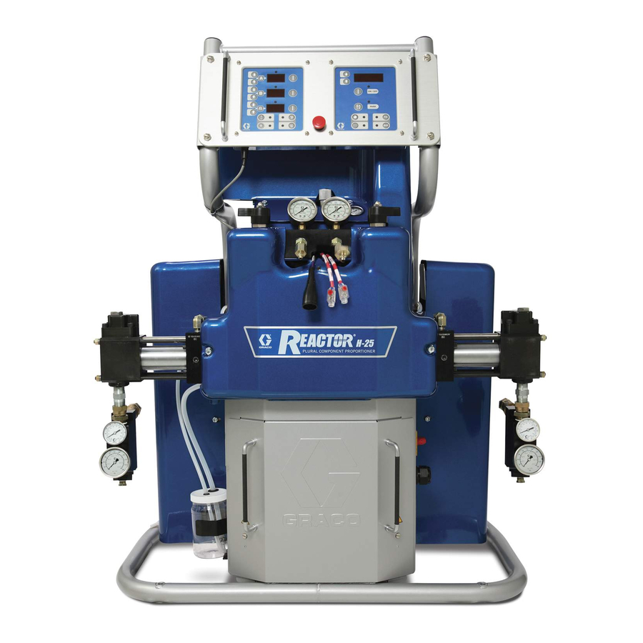
Graco Reactor H-25 Series Repair And Parts Manual
Hydraulic, heated, plural component proportioner
Hide thumbs
Also See for Reactor H-25 Series:
- Electrical diagrams (14 pages) ,
- Operation (38 pages) ,
- Electrical diagrams (22 pages)
Table of Contents
Advertisement
Repair - Parts
Hydraulic, Heated, Plural Component Proportioner. For spraying polyurethane foam and
polyurea coatings. For professional use only.
Not for use in explosive atmospheres.
Important Safety Instructions
Read all warnings and instructions in this manual.
Save these instructions.
See page 3 for model information, including
maximum working pressure and approvals.
For patent information, see
www.graco.com/patents.
Model H-40 Shown
312063Z
EN
TI9830a
Advertisement
Table of Contents

Related Manuals for Graco Reactor H-25 Series


Summary of Contents for Graco Reactor H-25 Series
- Page 1 Not for use in explosive atmospheres. Important Safety Instructions Read all warnings and instructions in this manual. Save these instructions. See page 3 for model information, including maximum working pressure and approvals. Model H-40 Shown For patent information, see www.graco.com/patents. TI9830a...
-
Page 2: Table Of Contents
Graco Standard Warranty ....74 Graco Information ......74... -
Page 3: Models
Models Models H-25 SERIES Max Flow Approximate Maximum Fluid Full Load Primary Rate Output per Hydraulic Working Peak Amps* Voltage System Heater lb/min Cycle (A+B) Pressure Pressure Part, Series Per Phase (phase) Watts† Watts (kg/min) gal. (liter) Ratio psi (MPa, bar) 255400, F 230V (1) 15,960... - Page 4 Models H-XP3 SERIES Approximate Maximum Fluid Full Load Primary Max Flow Output per Hydraulic Working Part, Peak Amps* Voltage System Heater Rate Cycle (A+B) Pressure Pressure Series Per Phase (phase) Watts† Watts gpm (lpm) gal. (liter) Ratio psi (MPa, bar) 253403, E 230V (1) 23,100...
-
Page 5: Supplied Manuals
Order Part 15M334 for a compact disk of Reactor manuals translated in several languages. Order Part manuals translated in several languages. 15B381 for a compact disk of Fusion manual translated in several languages. Manuals are also available at www.graco.com. Manuals in Manuals in English Description... -
Page 6: Warnings
• Ground equipment, personnel, object being sprayed, and conductive objects in work area. See Grounding instructions. • Use only Graco grounded hoses. • Check gun resistance daily. • If there is static sparking or you feel a shock, stop operation immediately. Do not use equipment until you identify and correct the problem. - Page 7 Warnings WARNING THERMAL EXPANSION HAZARD Fluids subjected to heat in confined spaces, including hoses, can create a rapid rise in pressure due to the thermal expansion. Over-pressurization can result in equipment rupture and serious injury. • Open a valve to relieve the fluid expansion during heating. •...
-
Page 8: Temperature Control Diagnostic Codes
Temperature Control Diagnostic Codes Temperature Control Diagnostic Codes • Thermocouple A or B (310) fails, is damaged, is not CAUTION touching the heater element (307), or has a poor To prevent damage to soft key buttons, do not press connection to the temperature control board. the buttons with sharp objects such as pens, plastic •... -
Page 9: E02: High Zone Current
Temperature Control Diagnostic Codes E02: High zone current NOTE: Before doing the following checks, note which zone (A, B, FTS, or all) has high fluid temperature. Table 1: Sensor Connector Continuity Checks 1. Turn main power OFF Pins Description Reading 2. -
Page 10: E04: Fluid Temperature Sensor (Fts) Or Thermocouple Disconnected
Temperature Control Diagnostic Codes E04: Fluid Temperature Sensor E05: Circuit board overheated (FTS) or thermocouple NOTE: Each module has an on-board temperature disconnected sensor. Heat is turned off if module temperature exceeds 185°F (85°C) within the heater module. 1. Check temperature sensor connections to long 1. -
Page 11: Motor Control Diagnostic Codes
Motor Control Diagnostic Codes Motor Control Diagnostic Codes E21: No component A Motor control diagnostic codes E21 through E27 appear on pressure display. transducer There are two types of motor control codes: alarms and 1. Check transducer A connection at J3 on motor warnings. - Page 12 Motor Control Diagnostic Codes NOTE: E24 can be an alarm or a warning, as desired. d. Check the analog gauges to see which pressure Set DIP switch on motor control board ON for alarm, is higher, and check if the display matches. OFF for warning.
-
Page 13: E27: High Motor Temperature
Motor Control Diagnostic Codes Slow E24 Errors If the gauge readings are not very close: Slow E24 errors occur gradually. The pressures are 1. Secure bleed lines in grounded waste containers, or balanced when you begin spraying, but slowly become route back to respective component A or B supply imbalanced until an E24 occurs. -
Page 14: E30: Momentary Loss Of Communication
Motor Control Diagnostic Codes E30: Momentary loss of communication If communication is lost between the display and the motor control board, the display will normally show E99. The motor control board will register E30 (the red LED will blink 30 times). When communications are reconnected, the display may show E30 briefly (no more than 2 seconds). -
Page 15: Troubleshooting
Troubleshooting Troubleshooting Reactor Electronics 2. Turn main power OFF 3. Allow equipment to cool. Try the recommended solutions in the order given for Before performing any troubleshooting procedures: each problem, to avoid unnecessary repairs. Also, determine that all circuit breakers, switches, and 1. - Page 16 Troubleshooting PROBLEM CAUSE SOLUTION Erratic display; display turns on and Low voltage. Ensure input voltage is within off. specifications, Display Module, page 41. Poor display connection. Check cable connections, Display Module, page 41. Replace damaged cable. Display cable damaged or corroded. Clean connections; replace cable if is damaged.
-
Page 17: Primary Heaters (A And B)
Troubleshooting Primary Heaters (A and B) 2. Turn main power OFF 3. Allow equipment to cool. Try the recommended solutions in the order given for Before performing any troubleshooting procedures: each problem, to avoid unnecessary repairs. Also, determine that all circuit breakers, switches, and 1. -
Page 18: Hose Heat System
Troubleshooting Hose Heat System 2. Turn main power OFF 3. Allow equipment to cool. Problems Before performing any troubleshooting procedures: Try the recommended solutions in the order given for each problem, to avoid unnecessary repairs. Also, 1. Relieve the pressure. See Pressure Relief determine that all circuit breakers, switches, and Procedure, page 26. - Page 19 Troubleshooting PROBLEM CAUSE SOLUTION Hose temperature exceeds setpoint. A and/or B heaters are overheating Check primary heaters for either a material. thermocouple problem or a failed element attached to thermocouple, E04: Fluid Temperature Sensor (FTS) or thermocouple disconnected, page 10. Faulty thermocouple connections.
-
Page 20: Hydraulic Drive System
Troubleshooting Hydraulic Drive System 2. Turn main power OFF 3. Allow equipment to cool. Problems Before performing any troubleshooting procedures: Try the recommended solutions in the order given for each problem, to avoid unnecessary repairs. Also, 1. Relieve pressure, page 26. determine that all circuit breakers, switches, and controls are properly set and wiring is correct before assuming there is a problem. - Page 21 Troubleshooting PROBLEM CAUSE SOLUTION Hydraulic pump does not develop Pump is not primed or lost its prime. Check electric motor rotation. Both pressure. Low or zero pressure with motor and hydraulic pump must screeching noise. rotate counterclockwise when viewed from shaft end. If rotation is incorrect, reverse leads L1 and L2.
-
Page 22: Proportioning System
Troubleshooting Proportioning System 2. Turn main power OFF 3. Allow equipment to cool. Problems Before performing any troubleshooting procedures: Try the recommended solutions in the order given for each problem, to avoid unnecessary repairs. Also, 1. Relieve the pressure. See Pressure Relief determine that all circuit breakers, switches, and Procedure, page 26. - Page 23 Troubleshooting PROBLEM CAUSE SOLUTION Pumps do not reverse direction or Bent or loose activator plate, rocker See Pumps Do Not Reverse pumps do not move. arm, or reversing switch. Direction, page 25. Loose piston packing bolt. See Pumps Do Not Reverse Direction, page 25.
- Page 24 Troubleshooting A (ISO) Inlet A (ISO) A (ISO) Supply Valve Over-pressure Proportioning Rupture Disk Pump B (Resin) Over-pressure Rupture Disk B (Resin) Proportioning Pump Directional Valve Activator Plate Reversing B (Resin) Inlet Switch Rocker Supply Valve . 1. Proportioning System Table 2.
- Page 25 Troubleshooting Pumps Do Not Reverse Direction b. If D19 and D20 do illuminate but the direction indication lights do not, the possible causes 1. For the proportioning pumps to reverse direction, include: the activator plate (219) must contact the rocker arm to activate the reversing switch (210).
-
Page 26: Repair
Repair Repair 5. Turn PRESSURE RELIEF/SPRAY valves (SA, SB) to PRESSURE RELIEF/CIRCULATION Repairing this equipment requires access to parts Route fluid to waste containers or supply tanks. that may cause electric shock or other serious injury Ensure gauges drop to 0. if work is not performed properly. -
Page 27: Flushing
Repair Flushing Proportioning Pumps Flush equipment only in a well-ventilated area. Do not spray flammable fluids. Do not turn on heaters while NOTE: See your proportioning pump manual for repair flushing with flammable solvents. instructions. • Flush out old fluid with new fluid, or flush out old 1. - Page 28 Repair 7. See F . 2. Disconnect the B (Resin) side pump Torque to 200 in-lb (22.6 N•m). inlet and outlet lines. Remove the pin (219) from the clevis (218) to disconnect the pump from the hydraulic cylinder (201). Remove the four screws (203) holding the pump to the spacers (413) of the cylinder.
-
Page 29: Circuit Breaker Module
Repair Circuit Breaker Module Table 3: Circuit Breakers, see F Ref. Size Component Hose/Transformer 1. Turn main power OFF . Disconnect power Secondary Side supply. Turn circuit breakers on to test. Transformer Primary 812A 25A, 40A, or Heater A 50A* 812B 25A, 40A, or Heater B... -
Page 30: Electric Motor
Repair Electric Motor Installation 1. Place motor on unit. Removal 2. Fasten motor with screws. 3. Connect the wires, using wire nuts. Refer to the 1. Turn main power OFF . Disconnect power Reactor Electrical Diagram manual and the diagram inside the motor junction box cover. -
Page 31: Motor Control Board
Repair Motor Control Board Table 4: DIP Switch (SW2) Settings NOTE: Motor control board has one red LED (D11). Switch ON (up) OFF (down) Power must be on to check. See F . 5 for location. Function is: Switch 1 Motor soft start ON Motor soft start (factory default) - Page 32 Repair Motor Control DIP Switch (SW2) Settings Models H-25, H-40, H-50 J3 (A) J8 (B) 1 2 3 4 ti3178c-3 Models H-XP2 & H-XP3 1 2 3 4 ti3178c-4 Apply 110009 thermal heatsink compound to mating surfaces. ti7724a . 5 Motor Control Board 312063Z...
-
Page 33: Transducers
Repair Transducers 4. Disconnect transducer cables at board; see F . 5, page 32. Reverse A and B connections and check if diagnostic code follows; see E21: No component A transducer, page 11. 1. Turn main power OFF . Disconnect power supply. -
Page 34: Temperature Control Module
Repair Temperature Control Module Table 6: Temperature Control Module Connections Connector Description DATA (A) Data reporting HOSE T/C P; FTS (purple) HOSE T/C R; FTS (red) HOSE T/C S; FTS (silver (unshielded bare wire)) HEATER T/C B, Y; Thermocouple (yellow) SENSOR (B) HEATER T/C B, R;... - Page 35 Repair Test SCR Circuit Replacing Temperature Control Assembly Modules 1. Test the SCR circuit in the on position: NOTICE a. Make sure everything is connected, including the hose. Before handling assembly, put on a static conductive wrist strap to protect against static discharge which can damage assembly.
-
Page 36: Primary Heaters
Repair Primary Heaters Line Voltage The primary heaters output their rated wattage at 230 Vac. Low line voltage will reduce power available and Heater Element the heaters will not perform at full capability. Thermocouple 1. Turn main power OFF . Disconnect power 1. - Page 37 Repair 9. Route wires (S) into cabinet and thread into bundle 11. Turn on heaters A and B simultaneously to test. as before. Reconnect wires to board. Temperatures should rise at same rate. If one heater is low, loosen ferrule nut (N) and tighten 10.
-
Page 38: Heated Hose
Repair Heated Hose 4. Test with ohmmeter between pins of cable connector. NOTE: Refer to your heated hose manual for hose replacement parts. Pins Result 1 to 2 approximately 35 ohms per 50 ft (15.2 m) of Check Hose Connectors hose, plus approximately 10 ohms for FTS 1 to 3 infinity... -
Page 39: Fluid Temperature Sensor (Fts)
Repair Fluid Temperature Sensor (FTS) Pins Result Test/Removal 1 to FTS component A infinity fitting (ISO) 4. If FTS fails any test, replace FTS. 1. Turn main power OFF . Disconnect power supply. 5. Disconnect air hoses (C, L), and electrical connectors (D). - Page 40 Repair Transformer Primary Check 3. To verify transformer voltage, turn on hose zone. Measure voltage from 18CB-2 to POD-HOSE-P15-2; see Reactor Electrical Diagrams manual. 1. Turn main power OFF Model Secondary Voltage 2. Locate the two smaller (10 AWG) wires coming out of transformer.
-
Page 41: Display Module
Repair Display Module between cable bushing and cover (504) with screws (512). Temperature and Pressure Displays Red Stop Button CAUTION CAUTION Before handling board, put on a static conductive Before handling board, put on a static conductive wrist strap to protect against static discharge which wrist strap to protect against static discharge which can damage board. - Page 42 Repair Apply medium strength thread sealant. ti2574a Detail of Membrane Switches and Display Boards Temperature Display Pressure Display 502c 502a 502b 501c 501a 501b ti3172a . 13 Display Module 312063Z...
-
Page 43: Inlet Fluid Strainer Screen
Repair Inlet Fluid Strainer Screen 59g* The inlet strainer at each proportioning pump filters out solid matter that can plug the inlet check valves. Inspect the screens daily as part of the startup routine, and clean as required. ti9886a Isocyanate can crystallize from moisture contamination . -
Page 44: Change Hydraulic Fluid And Filter
Repair Change Hydraulic Fluid and 3. Drain the reservoir and rinse with clean lubricant. Filter 4. When the reservoir is clean, fill with fresh lubricant. 5. Thread the reservoir onto the cap assembly and place it into the bracket. 6. Push the larger diameter supply tube (ST) approximately 1/3 of the way into the reservoir. - Page 45 Repair 5. Place a rag around base of oil filter (135) to prevent b. Screw filter on snug, then an additional 1/4 turn. oil from spilling. Unscrew filter 1/4-3/4 turn to break air lock in filter. Wait five minutes to allow oil in filter 8.
-
Page 46: Parts
Parts Parts 42 See page 50 See page 49 See page 50 See page 49 See page 47 See pages 59 - 61 ti9831a 312063Z... - Page 47 Parts Detail of Cabinet Area 8.0 kW Heater Bracket (Ref. 36) Shown 25, 147 See page 48 54 TI9834b 312063Z...
- Page 48 Parts Left Side of Cabinet 55, 56 TI9835a 8 (Ref) Right Side of Cabinet 103 (Ref) TI9836a 312063Z...
- Page 49 Parts Detail, Fluid Manifold Area 7, see page 65 717 (Ref) 111 (Ref) TI9838a Detail, Proportioner Area 111 (Ref) 59, see page 51 See page 58 59, see page 51 312063Z...
- Page 50 Parts Detail, Electric Motor Area 111 (Ref) 118 (Ref) ti7709a Detail, Hydraulic Reservoir Area 111 (Ref) 119, 120 111 (Ref) 115 60 133 125 142, 143 See page 51 See page 47 1 (Ref) TI9832b 312063Z...
- Page 51 Parts Ref. 59, Fluid Inlet Kit A Side 59d B Side 59h 59j TI9841a 59k NOTE: Fluid Inlet Kit (59) has two versions: Series A and Series B. Fluid Inlet Kit Series A uses a flat gasket (59h) and can be identified by a white seal.
-
Page 52: Parts Used On All Models
Parts Parts Used on All Models Ref. Part Description Qty. Ref. Part Description Qty. 45 189930 LABEL, safety, electric shock ---- HEATER; see page 54 for part hazard numbers 247844 BRACKET, reservoir, lube ---- MOTOR; see page 54 for part 247845 PULLEY, drive numbers 803889 BELT... - Page 53 Parts Ref. Part Description Qty. Ref. Part Description Qty. 66 ---- CONNECTOR, 2 PIN, motor 247857 H-25, H-XP2 models only 15H512 LABEL, control power; see page 54 for part 15H204 KNOB, pressure numbers 117560 SCREW, set, socket hd 117284 GRILL, fan guard 247793 HOSE, inlet, coupled ---- SWITCH, added pole;...
-
Page 54: Parts That Vary By Model
Parts Parts that Vary by Model Use the following tables to find parts that vary by model. See Parts, starting on page 46 for parts used on all models. H-25 and H-XP2 Models 255400 255401 255402 255403 255404 255405 255406 255407 255408 H-25... - Page 55 Parts H-40 and H-XP3 Models 253400 253401 253402 253403 253404 253405 253407 253408 H-40 H-40 H-40 H-XP3 H-XP3 H-XP3 H-40 H-40 12.0 kW 15.3 kW 15.3 kW 12.0 kW 20.0 kW 20.0 kW 20.4 kW 20.4 kW (230V, (230V, (400V, (230V, 1 (230V, (400V,...
- Page 56 Parts H-50 Models 253725 253726 253727 256505 256506 H-50 H-50 H-50 H-50 H-50 12.0 kW 15.3 kW 15.3 kW 20.4 kW 20.4 kW Qty. Ref. Description (230V, 1 phase) (230V, 3 phase) (400V, 3 phase) (230V, 3 phase) (400V, 3 phase) HEATER;...
-
Page 57: Sub Assemblies
Parts Sub Assemblies Proportioner Assembly Torque to 10-15 ft-lb (13.6-20.3 N•m). 312063Z... - Page 58 Parts Proportioner Assembly Ref. Part Description Qty. Ref. Part Description Qty. 222 100206 BUSHING 201 295027 CYLINDER, hydraulic, w/spacers; 223 15H524 ACCUMULATOR, pressure;1/4 npt see page 62 for parts 224 155541 FITTING, union, swivel, 90 degrees 202 ---- PUMP; see manual 312068 226 121312 ELBOW;...
-
Page 59: 10.2 Kw And 6.0 Kw Heaters
Parts 10.2 kW and 6.0 kW Heaters (Two Per Machine) Parts 247833 and 247834 r_247833_312063 Apply 110009 thermal heatsink compound. Ref. Part Description Qty. Ref. Part Description Qty. 310 117484 SENSOR 301 ---- HOUSING, heater 311 100518 SCREW, machine, pan hd 303 121309 ADAPTER, 3/4 SAE-ORB x 1/2 in. -
Page 60: 8.0 Kw Dual Zone Heater
Parts 8.0 kW Dual Zone Heater (One Per Machine) Part 247815 r_247815_312063 Apply 110009 thermal heatsink compound. Ref. Part Description Qty. Ref. Part Description Qty. 309 15B135 MIXER, immersion heater 301 ---- HOUSING, heater 310 117484 SENSOR 302 15H302 FITTING, reducer 311 100518 SCREW, machine, pan hd 303 121319 ADAPTER, 1/2 npt(m) x 1/2 in. -
Page 61: 7.65 Kw Single Zone Heater
Parts 7.65 kW Single Zone Heater (Two Per Machine) Part 247813 r_247813_312063 Apply 110009 thermal heatsink compound. Ref. Part Description Ref. Part Description 117484 SENSOR ---- HOUSING, heater 100518 SCREW, machine, pan hd 121309 ADAPTER, 3/4 SAE-ORB x 1/2 in. JIC 15H305 PLUG, hollow 15H304 PLUG 295607 PLUG;... -
Page 62: Hydraulic Cylinder
Parts Hydraulic Cylinder Rod Bushing Detail See Rod Bushing Detail ti7727a Ref. Part Description Qty. Ref. Part Description Qty. 411 295645 WIPER, rod 401 295029 PLATE, retainer 412 296644 SEAL, shaft 402 295030 CYLINDER 413 295032 SPACER, proportioning pump 403 295031 BUSHING, rod 414 261861 SPACER, reverse switch 404 296642 PISTON 415 295034 ROD, tie... -
Page 63: Display
Parts Display 20 (Ref) ti2574a 502a 502c 502b 501c 501a 501b ti3172a Ref. Part Description Qty. Ref. Part Description Qty. 15B291 PLATE 24G884 DISPLAY, pressure; includes 501a-501c 246287 HARNESS, wire, red stop button 501a 24G882 .BOARD, circuit 117499 HANDLE 501b 246478 .SWITCH, membrane 117523 NUT, cap;... -
Page 64: Temperature Control
Parts Temperature Control To B Heater Module To A Heater Module To Hose Heater Module TI9843a Ref. Part Description Qty. 601 247772 PANEL, module mounting 602 247827 HOUSING, control module 603 247828 HOUSING, heater module 604 115942 NUT, hex 605 247801 CABLE, communication 606 247825 KIT, cover, connector with screws 312063Z... -
Page 65: Fluid Manifold
Parts Fluid Manifold Torque to 355-395 in-lb (40.1-44.6 N•m). Apply sealant (113500) to threads. Valve must be closed with handle position as shown on drawing. ** Apply PTFE tape or thread sealant to tapered threads. 702a 702b TI9839b Ref. Part Description Qty. -
Page 66: Circuit Breaker Modules
Parts Circuit Breaker Modules A - 230V, 3 Phase Circuit Breaker Modules NOTE: For wiring and cable connections, refer to electrical diagrams manual, supplied. See page 69 for parts. 803, 804 168BR 187CB 172CB 178CB 197CB B - 400V, 3 Phase Circuit Breaker Modules NOTE: For wiring and cable connections, refer to electrical diagrams manual, supplied. - Page 67 Parts C - 230V, 1 Phase Circuit Breaker Modules NOTE: For wiring and cable connections, refer to electrical diagrams manual, supplied. See page 69 for parts. 803, 804 168BR 197CB 172CB 178CB 187CB D - 230V, 3 Phase Circuit Breaker Modules NOTE: For wiring and cable connections, refer to electrical diagrams manual, supplied.
- Page 68 Parts E - 400V, 3 Phase Circuit Breaker Modules NOTE: For wiring and cable connections, refer to electrical diagrams manual, supplied. See page 69 for parts. 803, 804 178CB 187CB 197CB 172CB 312063Z...
- Page 69 Parts Circuit Breaker Modules Parts List Breaker Modules Ref. Description 230V, 3 phase 400V, 3 phase 230V, 1 phase 230V, 3 phase 400V, 3 phase Qty. 255028 255028 255028 255028 255028 801 RAIL, mounting 255045 255045 255045 255045 255045 802 CLAMP, block, end 255043 255043 255043...
-
Page 70: Dimensions
Dimensions Dimensions Dimension in. (mm) Dimension in. (mm) F (side mounting holes) 16.25 (413) A (height) 55.0 (1397) G (mounting post inner diameter) 0.44 (11) B (width) 39.6 (1006) H (front mounting post height) 2.0 (51) C (depth) 18.5 (470) J (rear mounting post height) 3.6 (92) D (front mounting holes) - Page 71 Dimensions 312063Z...
-
Page 72: Technical Specifications
Technical Specifications Technical Specifications Reactor H-25, H-40, H-50, H-XP2, and H-XP3 Metric Fluid Circulation Ports 1/4 npsm(m), with plastic 1/4 npsm(m), with plastic tubing, 250 psi maximum tubing, 1.75 MPa, 17.5 bar Maximum Fluid Temperature 190 °F 88 °C Hydraulic reservoir capacity 3.5 gal. - Page 73 Technical Specifications Reactor H-25, H-40, H-50, H-XP2, and H-XP3 Metric Weight Units with 8.0 kW Heaters 535 lb 243 kg Units with 12.0 kW Heaters 597 lb 271 kg Units with 15.3 kW Heaters (H-25/H-XP2 562 lb 255 kg models) Units with 15.3 kW Heaters (H-40/H-XP3/H-50 597 lb 271 kg...
-
Page 74: Graco Standard Warranty
With the exception of any special, extended, or limited warranty published by Graco, Graco will, for a period of twelve months from the date of sale, repair or replace any part of the equipment determined by Graco to be defective.
Need help?
Do you have a question about the Reactor H-25 Series and is the answer not in the manual?
Questions and answers
Bonjour J'ai un problème avec code d'erreur E03 quand j'appuie sur bouton pour chauffer produits A et B sa tombe courant directement
Error code E03 for the Graco Reactor H-25 Series indicates a failure related to the temperature control system when heating products A and B. It can be caused by a failed thermocouple, a damaged thermocouple, a thermocouple not touching the heater element, or a poor connection to the temperature control board. This error can be cleared by pressing the appropriate reset button.
This answer is automatically generated