Table of Contents
Advertisement
Advertisement
Table of Contents

Related Manuals for Pilz PNOZ X11P


Summary of Contents for Pilz PNOZ X11P
- Page 1 PNOZ X11P Safety relays Operating Manual-21030-EN-07...
- Page 2 Preface This document is a translation of the original document. All rights to this documentation are reserved by Pilz GmbH & Co. KG. Copies may be made for internal purposes. Suggestions and comments for improving this documentation will be gratefully received.
-
Page 3: Table Of Contents
Safety features Block diagram/terminal configuration Function Description Operating modes Timing diagram Installation Wiring Preparing for operation Operation Status indicators Faults – Interference Dimensions in mm Technical details Safety characteristic data Supplementary data Service life graph Operating Manual PNOZ X11P 21030-EN-07... - Page 4 Contents Remove plug-in terminals Order reference EC declaration of conformity Operating Manual PNOZ X11P 21030-EN-07...
-
Page 5: Introduction
PNOZ X11P Introduction Validity of documentation This documentation is valid for the product PNOZ X11P. It is valid until new documentation is published. This operating manual explains the function and operation, describes the installation and provides guidelines on how to connect the product. -
Page 6: Safety
Safety Intended use The safety relay PNOZ X11P provides a safety-related interruption of a safety circuit. The safety relay meets the requirements of EN 60947-5-1, EN 60204-1 and VDE 0113-1 and may be used in applications with E-STOP pushbuttons... -
Page 7: Warranty And Liability
Note for overvoltage category III: If voltages higher than low voltage (>50 VAC or >120 VDC) are present on the unit, connected control elements and sensors must have a rated insulation voltage of at least 250 V. Operating Manual PNOZ X11P 21030-EN-07... -
Page 8: Unit Features
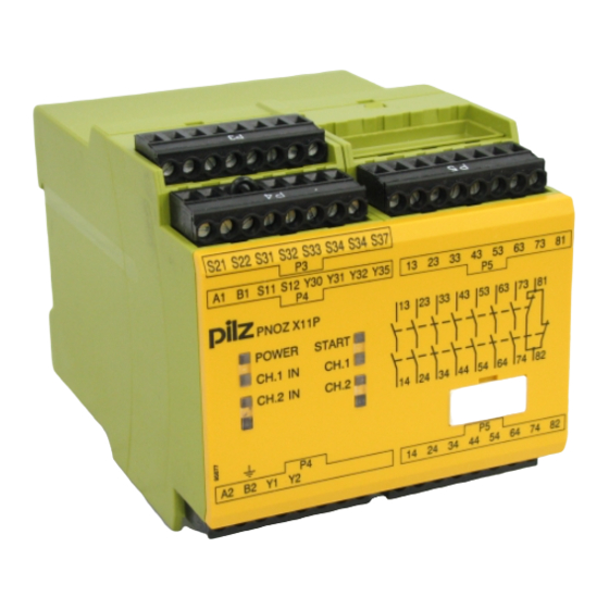
The correct opening and closing of the safety function relays is tested automatically in each on-off cycle. Block diagram/terminal configuration A1 A2 B1 B2 *Insulation between the non-marked area and the relay contacts: Basic insulation (over- voltage category III), Protective separation (overvoltage category II) Operating Manual PNOZ X11P 21030-EN-07... -
Page 9: Function Description
PNOZ X11P Function Description The safety relay PNOZ X11P provides a safety-oriented interruption of a safety circuit. When supply voltage is supplied the "POWER" LED is lit. The unit is ready for operation when the feedback loop Y1-Y2 and the start circuit S33-S34 are closed. The "START" LED is lit. -
Page 10: Timing Diagram
Use the notch on the rear of the unit to attach it to a DIN rail (35 mm). When installed vertically: Secure the unit by using a fixing element (e.g. retaining bracket or end angle). Operating Manual PNOZ X11P 21030-EN-07... -
Page 11: Wiring
Important for detection of shorts across contacts: As this function for detecting shorts across contacts is not failsafe, it is tested by Pilz during the final control check. If there is a danger of exceeding the cable length, we recommend the following test once the unit is installed: 1. -
Page 12: Preparing For Operation
Safety gate with detection of shorts across contacts NOTICE With single-channel wiring the safety level of your machine/plant may be lower than the safety level of the unit (see Safety characteristic data [ 27]). Operating Manual PNOZ X11P 21030-EN-07... - Page 13 The unit starts up automatically when the safeguard is reset, e.g. when the E-STOP pushbutton is released. Use external circuit measures to prevent an unexpected restart. without feedback loop monitor- Feedback loop with feedback loop monitoring Link or contacts from external contactors Operating Manual PNOZ X11P 21030-EN-07...
-
Page 14: Operation
LEDs indicate the status and errors during operation: LED on POWER Supply voltage is present. START Start circuit is closed. CH.1 IN Channel 1 input circuit is closed. CH.2 IN Channel 2 input circuit is closed. Operating Manual PNOZ X11P 21030-EN-07... -
Page 15: Faults - Interference
Contact malfunctions: If the contacts have welded, reactivation will not be possible after the input circuit has opened. LED "POWER" does not light: Short circuit or no supply voltage. Dimensions in mm * with spring-loaded terminals Operating Manual PNOZ X11P 21030-EN-07... -
Page 16: Technical Details
100 Ohm Dual-channel with de- tection of shorts across contacts at UB DC 15 Ohm 15 Ohm 15 Ohm Dual-channel with de- tection of shorts across contacts at UB AC 20 Ohm 20 Ohm 20 Ohm Operating Manual PNOZ X11P 21030-EN-07... - Page 17 In accordance with the standard EN 60947-5-1 EN 60947-5-1 EN 60947-5-1 Utilisation category of safety contacts AC15 at 230 V 230 V 230 V Max. current DC13 (6 cycles/min) at 24 V 24 V 24 V Max. current Operating Manual PNOZ X11P 21030-EN-07...
- Page 18 Blow-out fuse, slow Blow-out fuse, gG 10 A 10 A 10 A Circuit breaker 24 V AC/DC, characteristic Contact material AgSnO2 + 0,2 µm Au AgSnO2 + 0,2 µm Au AgSnO2 + 0,2 µm Au Operating Manual PNOZ X11P 21030-EN-07...
- Page 19 450 ms 450 ms 450 ms With manual start max. 680 ms 680 ms 680 ms With monitored start 390 ms 390 ms 390 ms typ. With monitored start max. 550 ms 550 ms 550 ms Operating Manual PNOZ X11P 21030-EN-07...
- Page 20 Rated insulation voltage 250 V 250 V 250 V Rated impulse withstand 4 kV 4 kV 4 kV voltage Protection type Housing IP40 IP40 IP40 IP20 IP20 IP20 Terminals Mounting area (e.g. control cabinet) IP54 IP54 IP54 Operating Manual PNOZ X11P 21030-EN-07...
- Page 21 94 mm 94 mm Width 90 mm 90 mm 90 mm Depth 121 mm 121 mm 121 mm Weight 640 g 640 g 640 g Where standards are undated, the 2017-01 latest editions shall apply. Operating Manual PNOZ X11P 21030-EN-07...
- Page 22 15 Ohm 15 Ohm 15 Ohm Dual-channel with de- tection of shorts across contacts at UB AC 20 Ohm 20 Ohm 20 Ohm Semiconductor outputs 787080 787083 787086 Number Voltage 24 V 24 V 24 V Operating Manual PNOZ X11P 21030-EN-07...
- Page 23 In accordance with the standard EN 60947-5-1 EN 60947-5-1 EN 60947-5-1 Utilisation category of safety contacts AC15 at 230 V 230 V 230 V Max. current DC13 (6 cycles/min) at 24 V 24 V 24 V Max. current Operating Manual PNOZ X11P 21030-EN-07...
- Page 24 Blow-out fuse, slow Blow-out fuse, gG 10 A 10 A 10 A Circuit breaker 24 V AC/DC, characteristic Contact material AgSnO2 + 0,2 µm Au AgSnO2 + 0,2 µm Au AgSnO2 + 0,2 µm Au Operating Manual PNOZ X11P 21030-EN-07...
- Page 25 450 ms 450 ms 450 ms With manual start max. 680 ms 680 ms 680 ms With monitored start 390 ms 390 ms 390 ms typ. With monitored start max. 550 ms 550 ms 550 ms Operating Manual PNOZ X11P 21030-EN-07...
- Page 26 Rated insulation voltage 250 V 250 V 250 V Rated impulse withstand 4 kV 4 kV 4 kV voltage Protection type Housing IP40 IP40 IP40 IP20 IP20 IP20 Terminals Mounting area (e.g. control cabinet) IP54 IP54 IP54 Operating Manual PNOZ X11P 21030-EN-07...
-
Page 27: Safety Characteristic Data
[1/h] 2015 2015 2015 Category [year] – PL e Cat. 4 SIL CL 3 2,31E-09 SIL 3 2,03E-06 All the units used within a safety function must be considered when calculating the safety characteristic data. Operating Manual PNOZ X11P 21030-EN-07... -
Page 28: Supplementary Data
The wear is mainly caused by the electrical load; the mechanical load is negli- gible. Switching current (A) Example Inductive load: 0.2 A Utilisation category: AC15 Contact service life: 4 000 000 cycles Operating Manual PNOZ X11P 21030-EN-07... - Page 29 110 - 120 VAC; 24 VDC Spring-loaded terminals 787 083 PNOZ X11P 230 - 240 VAC; 24 VDC Screw terminals 777 086 PNOZ X11P C 230 - 240 VAC; 24 VDC Spring-loaded terminals 787 086 Operating Manual PNOZ X11P 21030-EN-07...
- Page 30 European Parliament and of the Council. The complete EC Declaration of Conformity is available on the Internet at www.pilz.com/support/downloads. Representative: Norbert Fröhlich, Pilz GmbH & Co. KG, Felix-Wankel-Str. 2, 73760 Ost- fildern, Germany Operating Manual PNOZ X11P...
- Page 31 Back cover Support Technical support is available from Pilz round the clock. Americas Australia Scandinavia +45 74436332 Brazil +61 3 95600621 +55 11 97569-2804 Spain Canada Europe +34 938497433 +1 888-315-PILZ (315-7459) Austria Switzerland Mexico +43 1 7986263-0 +41 62 88979-30...
Need help?
Do you have a question about the PNOZ X11P and is the answer not in the manual?
Questions and answers