
Related Manuals for Winco TransMotion TMM4


Summary of Contents for Winco TransMotion TMM4
- Page 1 TMM PUSH HANDLE ASSEMBLY FIELD INSTALLATION AND USAGE INSTRUCTIONS FOR TMM4, TMM5, TMM4 PLUS, TMM5 PLUS, TMM4-X, TMM5-X, TMM4 PLUS-X, AND TMM5 PLUS-X IMPORTANT - DO NOT DISCARD THESE INSTRUCTIONS. KEEP FOR FUTURE REFERENCE.
- Page 2 This page has been intentionally left blank.
-
Page 3: Table Of Contents
TMM PUSH HANDLE FIELD INSTALLATION AND USAGE INSTRUCTIONS TABLE OF CONTENTS IMPORTANT NOTES ABOUT THIS MANUAL ................4 SPECIAL NOTES - SIGNAL WORDS ....................4 TOOLS REQUIRED ........................... 5 PARTS INCLUDED ..........................5 REMOVING AN OLD PUSH HANDLE ASSEMBLY ..............6 INSTALLING A NEW PUSH HANDLE ASSEMBLY ............... -
Page 4: Important Notes About This Manual
TransMotion by Winco product. Read this document thoroughly before using the equipment or performing service or maintenance. If you are unable to understand the warnings, cautions, or instructions, contact Winco Customer Service before attempting to operate or service the equipment, otherwise injury or damage may result. -
Page 5: Tools Required
TMM PUSH HANDLE FIELD INSTALLATION AND USAGE INSTRUCTIONS TOOLS REQUIRED • (1) 3/16” Allen Wrench • (1) 1/2” Socket Wrench • (2) Thin 3/8” Open End Wrenches PARTS INCLUDED 1. Push Handle Assembly (TMA227-15) PART NUMBER DESCRIPTION QUANTITY IMAGE TMM-374-06 TMM5 PUSH BAR ASSEMBLY - LEFT TMM-373-06 TMM5 PUSH BAR ASSEMBLY - RIGHT... -
Page 6: Removing An Old Push Handle Assembly
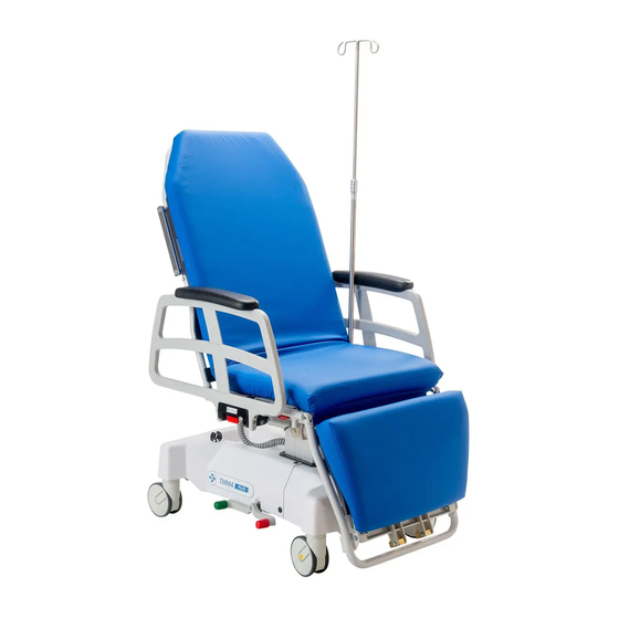
TMM PUSH HANDLE FIELD INSTALLATION AND USAGE INSTRUCTIONS REMOVING AN OLD PUSH HANDLE ASSEMBLY Fig. 1 Using the pendant, adjust the device into the chair position (Fig. 1). 2. Locate the bolt connecting the push handle to the back frame. The position of this bolt will be slightly different on the TMM4 and TMM5 Models (Fig. -
Page 7: Installing A New Push Handle Assembly
TMM PUSH HANDLE FIELD INSTALLATION AND USAGE INSTRUCTIONS INSTALLING A NEW PUSH HANDLE ASSEMBLY NOTE: FOR A TMM5 MODEL CHAIR, THE BOTTOM BOLT OF Fig. 1 THE SURGICAL BAR WILL NEED TO BE REMOVED USING A 3/16” ALLEN WRENCH AND THE SURGICAL BAR WILL NEED TO BE MOVED OUT OF THE WAY BEFORE INSTALLING A ←... - Page 8 TMM PUSH HANDLE FIELD INSTALLATION AND USAGE INSTRUCTIONS INSTALLING THE NEW PUSH HANDLE ASSEMBLY (CONTINUED) 2. Securley tighten the cap nut onto the bolt using the 3/8” allen wrench and 1/2” socket wrench (Fig. 3). ← Cap Nut 3. Slide one (1) push bar grip onto the push handle Fig.
-
Page 9: Push Handle Plunger Knob Installation
TMM PUSH HANDLE FIELD INSTALLATION AND USAGE INSTRUCTIONS PUSH HANDLE PLUNGER KNOB INSTALLATION REMOVING AN OLD PLUNGER KNOB Pull knob to release handle. Swing handle down and out of way (Fig. 1). ← Fig. 1 2. Place one 3/8” open end wrench near the knob. Pull the spring loaded inner section out with your fingers (Fig. -
Page 10: Installing A New Plunger Knob
TMM PUSH HANDLE FIELD INSTALLATION AND USAGE INSTRUCTIONS INSTALLING A NEW PLUNGER KNOB Fig. 1 Pull the inner rod out of the handle plunger knob (Fig. 1). 2. Slide the 3/8” open end wrench onto the flat grooves of the Fig. -
Page 11: Upholstery Care And Cleaning Instructions
TMM PUSH HANDLE FIELD INSTALLATION AND USAGE INSTRUCTIONS UPHOLSTERY CARE AND CLEANING INSTRUCTIONS Proper care is essential in ensuring the durability and reliability of TransMotion Medical upholstery. In general, all products should be: 1. Cleaned 2. Disinfected (in accordance with facility policy) 3. - Page 12 Document No.: IM TMA227-15 Field Installation and Usage Instructions Revision: A Copyright © 2020 Winco Mfg., LLC CONTACT US To arrange a demonstration or to speak with one of our associates, please feel free to contact us at: 800-237-3377 | WincoMfg.com | 5516 SW 1st Lane, Ocala, FL 34474 | Info@WincoMfg.com...
Need help?
Do you have a question about the TransMotion TMM4 and is the answer not in the manual?
Questions and answers