Table of Contents
Advertisement
Quick Links
Advertisement
Table of Contents

Related Manuals for oConnor 2560


Summary of Contents for oConnor 2560
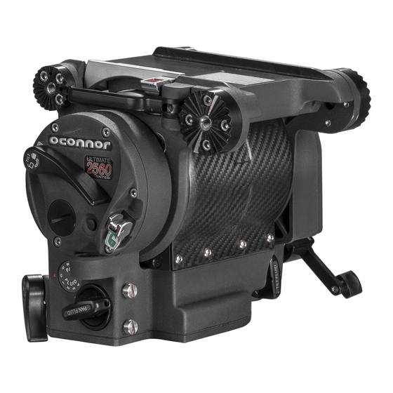
- Page 1 2560 Part No. C1260-0001 C1260-0002 www.ocon.com...
- Page 2 Vitec Videocom Ltd reserves the right to make changes to product design and functionality without notification. Trademarks OConnor® is a registered trademark of the Vitec Group Plc. All product trademarks and registered trademarks are the property of The Vitec Group Plc. All other trademarks and registered trademarks are the property of their respective companies.
-
Page 3: Table Of Contents
Contents Safety..........2 Cleaning . -
Page 4: Safety
Safety Important information on the safe installation and operation of WARNING! DO NOT fit the head to a tripod that cannot this product. Read this information before operating the product. support the combined mass of the head and its full payload. For your personal safety, read these instructions. -
Page 5: About This User Guide
This guide describes the installation, configuration and operation of the OConnor 2560 fluid head. The 2560 features OConnor's step-less counterbalance system as well as ultra-smooth pan and tilt fluid drag designed for cine style shooting. The C1260-0002 is supplied with a protective plastic base,... -
Page 6: Components
Components Front View Mitchell Key marker Mitchell Key Attach either Mitchell Base (shown) or 150mm ball base using 4 x Hex screws Front end handle / accessory mounting rosette Slide plate scale Platform release lever Platform release lever safety catch Rear large pan handle / accessory mounting rosette Tilt centre lock Bubble illumination button... -
Page 7: Rear View
Components Rear View Euro Style Quick Release Plate Rear large pan handle / accessory mounting rosette Platform Front small pan handle / accessory mounting rosette Counterbalance numerical display Folding counter balance adjustment crank Tilt fluid drag display Tilt fluid drag adjustment knob Eyepiece leveller mounting screws Camera plate clamp release lever Camera mounting plate... -
Page 8: Box Contents C1260 - 0001
Components Box Contents C1260 - 0001 Item Description 2560 head Euro style quick release plate Pan handle Pan extension handle Mitchell tie down Mitchell base assembly 150mm tie down 150mm base assembly *Variant C1260-0002 consists of head only. -
Page 9: Optional Accessories
Components Optional Accessories Item Description Part No. Assistants box CSE-MFB100 Eye piece leveller C1504-1000 Tripods Cine HD Mitchell C1221-0001 Cine HD 150mm ball base C1221-0003 Cine HD Baby Mitchell C1221-0002 Cine HD Baby 150mm ball base C1221-0004 Pan handle 08409 Front handle C1260-1010 High hat Mitchell... -
Page 10: Installing The Head And Payload
Mounting the head Levelling the Head The 2560 is installed onto standard tripods using either the Mitchell After securely mounting the head on to the tripod, center the bubble base and tie down or the 150mm ball base and tie down as required. -
Page 11: Installation
Installation... -
Page 12: Mounting The Camera
Mounting the Camera The camera is attached to the head by means of a side loading platform Attach the mounting plate securely to the bottom of the camera in mechanism. the desired position. WARNING! Before fitting or adjusting the camera or payload the tilt lock pin must be engaged. -
Page 13: Fitting The Pan Handle
Installation Fitting the Pan Handle Pan Handle / accessory mounting rosettes are located at the front and rear of the head, on both the left and right sides. -
Page 14: Fore/Aft Balance
Installation Fore/Aft Balance Depending on the payload weight, it may be necessary to increase or decrease this setting to enable the payload to Ensure that the head is level before balancing. The camera and be correctly balanced fore and aft. payload should be fitted on the head, so that the load is balanced. - Page 15 Installation Hold and steady the camera, then disengage the tilt lock and observe how it moves and where it stops. If the camera tilts backwards (points upward), then the camera must be moved towards the front of the head (fore). If the camera cradle stops in a horizontal position (camera pointing directly forward), the balance is correct.
-
Page 16: Payload Weight And C Of G Height Adjustment
C of G heights that can be maintained in balance. The counterbalance can be adjusted all the way to zero (no counterbalance) and the head can still be tilted ±90º. 2560 Counterbalance 90 100 110 120 41 45 Camera Weight... -
Page 17: Adjusting The Centre Of Gravity (C Of G)
Installation Adjusting the Counter Balance CAUTION! Risk of damage to equipment. Be prepared to prevent the camera from falling away suddenly Tilt the camera approx. 45° upward and release it. If the camera stays in the same position when released, the camera is correctly balanced with the C of G on the tilt axis. -
Page 18: Operation
Operation Operating the Pan and Tilt Locks The pan and tilt friction locks are operated by levers on the left of the head. The locks should be applied whenever the camera/head is left unattended. After prolonged use, if the lock does not fully engage at the end of the lock lever travel, refer to Adjust Lock Levers on page 19. The levers are designed so they can be released simultaneously with one hand. -
Page 19: Pan And Tilt Fluid Drag
Operation Pan and Tilt Fluid Drag The pan drag adjustment knob is located on the lower right rear of the head, and the tilt drag adjustment knob on the lower left of the head. Both controls are continuously adjustable from 0 to 9. To increase drag, turn the knob clockwise, towards a higher setting. To decrease drag, turn the knob counter-clockwise, towards a lower setting. -
Page 20: Battery Replacement
Maintenance Battery Replacement The battery illuminates the bubble level. It should be replaced whenever the illumination becomes inadequate. Use a coin or flat blade screwdriver to unscrew the battery cover. Carefully pull the battery out of its compartment. Fit a replacement CR 2032 3v battery in the compartment, ensuring that the positive side (+) of the battery faces outermost. -
Page 21: Maintenance
Maintenance Adjust Lock Levers Pull the lock lever off the hexagonal shaft, rotate it approx. 30° away from the “locked” end of travel, and reinstall it. If the pan and/or tilt friction locks do not fully engage at the end of the lock lever travel, adjust the lever position as follows: Tighten the screw. -
Page 22: Cleaning
Maintenance Cleaning We encourage regular cleaning of the product. During normal use the only cleaning required should be a regular wipe over with a lint-free cloth. Cover the head when not in use. Dirt accumulated during storage or periods of non-use may be removed with a vacuum cleaner. CAUTION! Salt water will damage the head! If product comes into contact with salt water, immediately rinse with distilled water and dry with compressed moving air. -
Page 23: Technical Specification
Technical Specification Physical Data Height Width 20.3 cm (8 in.) 28.7 cm (11.3 in.) Weight Depth 7.3 kg (16.2 lb) 19.1 cm (7.5 in) Tilt *Maximum payload ±90º throughout entire 40.72 kg (90 lb) counterbalance range, zero to max. Operating Temp. Storage temp. -
Page 24: General Notices
General Notices Declaration of Conformity Visit our website for information on how to safely dispose of this product and its packaging. In countries outside the EU: Dispose of this product at a collection point for the recycling of electrical and electronic equipment according to your local government regulations. - Page 28 Publication part No. C1260-4980/1 OConnor ™ www.ocon.com A Vitec Group brand...
Need help?
Do you have a question about the 2560 and is the answer not in the manual?
Questions and answers