
Related Manuals for Ditch Witch JT100


Summary of Contents for Ditch Witch JT100
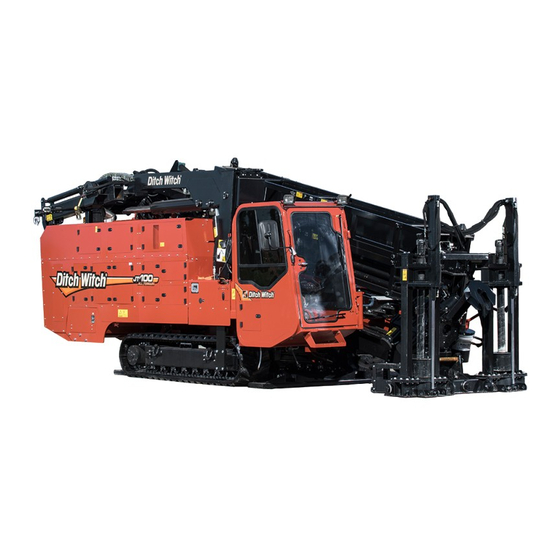
- Page 1 JT100/JT100 All Terrain Tier 4 Operator’s Manual Issue 2.1 053-2814 Original Instruction...
-
Page 2: Table Of Contents
JT100/JT100 All Terrain Operator’s Manual Overview - 1 Overview Chapter Contents Serial Number Location ..... . 2 Intended Use ......3 Equipment Modification . -
Page 3: Serial Number Location
JT100/JT100 All Terrain Operator’s Manual Overview - 2 Serial Number Location Serial Number Location Record serial numbers and date of purchase in spaces provided. Drilling unit serial number is located as shown. Item date of manufacture date of purchase drilling unit serial number... -
Page 4: Intended Use
Intended Use Intended Use The JT100/JT100 All Terrain is a self-contained horizontal directional drilling unit capable of drilling and backreaming through solid rock, cobblestone, broken rock, gravel, and other soil/rock mixes, as well as less extreme soil conditions. It is designed to install buried cable and pipe at distances to 2,000’ (610 m) depending on soil conditions and is intended for operation in ambient temperatures from 0°... -
Page 5: Unit Components
JT100/JT100 All Terrain Operator’s Manual Overview - 4 Unit Components Unit Components 1. Driver/loader attachment (optional) 8. Tracks 2. Pipeloader 9. Operator’s station 3. Front and rear wrenches 10. Drill frame 4. Spindle 11. Anchoring system (optional) 5. Rotation carriage ®... -
Page 6: Fcc Statement - Internal Transmitter
JT100/JT100 All Terrain Operator’s Manual Overview - 5 FCC Statement - Internal Transmitter FCC Statement - Internal Transmitter U.S. This device complies with Part 15 of the FCC Rules. Operation is subject to the following two conditions: (1) this device may not cause harmful interference, and (2) this device must accept any interference received, including interference that may cause undesired operation. -
Page 7: Operator Orientation
JT100/JT100 All Terrain Operator’s Manual Overview - 6 Operator Orientation Operator Orientation IMPORTANT: Top view of unit is shown. 1. Front of unit 2. Right side of unit 3. Rear of unit 4. Left side of unit j28om097t.eps About This Manual This manual contains information for the proper use of this machine. -
Page 8: Foreword
If you sell your equipment, be sure to give this manual to the new owner. If you need a replacement copy, contact your Ditch Witch dealer. If you need assistance in locating a dealer, visit our website at www.ditchwitch.com or write to the following address: The Charles Machine Works, Inc. - Page 9 Copyright 2016 by The Charles Machine Works, Inc. and Ditch Witch, Subsite Electronics, Power Pipe, SaverLok, DrillLok, and Rockmaster are registered trademarks of The Charles Machine Works, Inc. This product and its use may be covered by one or more patents at http://patents.charlesmachine.works.
- Page 10 JT100/JT100 All Terrain Operator’s Manual Contents - 9 Contents Overview machine serial number, information about the type of work this machine is designed to perform, basic machine components, and how to use this manual Foreword part number, revision level, and publication date of this manual, and factory contact...
- Page 11 JT100/JT100 All Terrain Operator’s Manual Contents - 10 Specifications machine specifications including weights, measurements, power ratings, and fluid capacities Support the warranty policy for this machine, and procedures for obtaining warranty consideration and training Service Record a record of major service performed on the machine Appendix ®...
-
Page 12: Safety
JT100/JT100 All Terrain Operator’s Manual Safety - 11 Safety Chapter Contents Guidelines ....... . 12 California Proposition 65 Warning . -
Page 13: Guidelines
• Fully inspect equipment before operating. Repair or replace any worn or damaged parts. Replace missing or damaged safety shields and safety signs. Contact your Ditch Witch dealer for assistance. • Use equipment carefully. Stop operation and investigate anything that does not look or feel right. -
Page 14: Emergency Procedures
JT100/JT100 All Terrain Operator’s Manual Safety - 13 Emergency Procedures Emergency Procedures Jobsite hazards could cause death or serious injury. Use correct equipment and work methods. Use and maintain proper safety equipment. Before operating any equipment, review emergency procedures and check that all safety precautions have been taken. -
Page 15: If An Electric Line Is Damaged
JT100/JT100 All Terrain Operator’s Manual Safety - 14 Emergency Procedures If an Electric Line is Damaged If you suspect an electric line has been damaged and you are on drilling unit or bonded equipment, DO NOT MOVE. Remain on drilling machine and take the following actions. The order and degree of action will depend on the situation. -
Page 16: If A Gas Line Is Damaged
JT100/JT100 All Terrain Operator’s Manual Safety - 15 Emergency Procedures If a Gas Line is Damaged Fire or explosion possible. Fumes could ignite and cause burns. No smoking, no flame, no spark. 275-419 (2P) Explosion possible. Serious injury or equipment damage could occur. -
Page 17: If A Fiber Optic Cable Is Damaged
JT100/JT100 All Terrain Operator’s Manual Safety - 16 Emergency Procedures If a Fiber Optic Cable is Damaged Do not look into cut ends of fiber optic or unidentified cable. Vision damage can occur. Contact utility company. If Machine Catches on Fire Perform emergency shutdown procedure and then take the following actions. -
Page 18: Driver/Loader Precautions
JT100/JT100 All Terrrain Operator’s Manual Safety - 17 Driver/Loader Precautions Driver/Loader Precautions Intended Use The driver/loader is to be used for driving anchors and loading and unloading pipe boxes only. Use in any other way is considered contrary to the intended use. - Page 19 JT100/JT100 All Terrrain Operator’s Manual Safety - 18 Driver/Loader Precautions Operation General Riding on boom or load will result in death or serious injury. No riders. Keep off. • Secure with shackle before lifting load. • Never use a sling bar or anything larger than the shackle prevent from closing. This prevents damage to material being hoisted and helps prevent injury to personnel.
- Page 20 JT100/JT100 All Terrrain Operator’s Manual Safety - 19 Driver/Loader Precautions • Never swing a load over people. • Consider overall height of unit when moving under objects with low overhead clearance. • Operate controls smoothly and do not stop load sharply in midair so that it swings.
- Page 21 JT100/JT100 All Terrrain Operator’s Manual Safety - 20 Driver/Loader Precautions Near Electrical Power Lines Do not get boom near power lines. Death or serious injury will occur. Keep required distance between boom and power lines. Use a spotter. 270-1983 Never operate the driver/loader within 10’ (3 m) of electric power lines carrying up to 50 kV. Add 1’ (305 mm) of clearance for each additional 30 kV or less (see table on left).
-
Page 22: Safety Alert Classification
JT100/JT100 All Terrrain Operator’s Manual Safety - 21 Safety Alert Classifications Safety Alert Classifications These classifications and the icons defined on the following pages work together to alert you to situations which could be harmful to you, jobsite bystanders or your equipment. When you see these words and icons in the book or on the machine, carefully read and follow all instructions. -
Page 23: Machine Safety Alerts
JT100/JT100 All Terrrain Operator’s Manual Safety - 22 Machine Safety Alerts Machine Safety Alerts... - Page 24 JT100/JT100 All Terrrain Operator’s Manual Safety - 23 Machine Safety Alerts Moving tools will kill or injure. Never use pipe wrenches on drill string. 273-278 Moving parts could cut off hand or foot. Stay away. 275-184, 273-437, Rotating shaft will cause death or serious injury.
- Page 25 JT100/JT100 All Terrrain Operator’s Manual Safety - 24 Machine Safety Alerts Hot parts may cause burns. Do not touch until cool or wear gloves. 275-355 (2-P), 273-423 (2-P) Crushing weight could cause death or serious injury. Stay away. 275-326 Pressurized fluid or air could pierce skin and cause severe injury.
-
Page 26: Attachment Safety Alerts
JT100/JT100 All Terrrain Operator’s Manual Safety - 25 Attachment Safety Alerts Attachment Safety Alerts Driver/Loader Attachment Riding on boom or load will result in death or serious injury. No riders. Keep off. 274-962 Moving parts could cut off hand. Stay away. - Page 27 JT100/JT100 All Terrrain Operator’s Manual Safety - 26 Attachment Safety Alerts Auxiliary stabilizer must be properly installed with contact on firm surface before operating pipebox loader on the engine side of the unit. Working loads should be limited to those shown.
-
Page 28: Controls
JT100/JT100 All Terrain Operator’s Manual Controls - 27 Controls Chapter Contents Set-Up Console ......29 Tethered Driver/Loader Control . - Page 29 JT100/JT100 All Terrain Operator’s Manual Controls - 28 Miscellaneous Controls ..... 67 Engine Diagnostic Connector ....70 Battery .
-
Page 30: Setup Console
JT100/JT100 All Terrain Operator’s Manual Controls - 29 Setup Console Setup Console 1. Engine throttle switch 5. Right rear stabilizer control 2. Remote engine stop switch 6. Left front stabilizer control 3. Auxiliary light switch 7. Right front stabilizer control 4. - Page 31 JT100/JT100 All Terrain Operator’s Manual Controls - 30 Setup Console Item Description Notes 2. Remote engine stop To stop engine, press. IMPORTANT: switch To restart engine, turn ignition • If this switch is used to stop off and then back to start.
- Page 32 JT100/JT100 All Terrain Operator’s Manual Controls - 31 Setup Console Item Description Notes 6. Left front stabilizer To lower, push. Lower both front stabilizers to the control ground together and then adjust To raise, pull. individually. 7. Right front stabilizer To lower, push.
-
Page 33: Tethered Driver/Loader Control
JT100/JT100 All Terrain Operator’s Manual Controls - 32 Tethered Driver/Loader Control Tethered Driver/Loader Control j28om013t.eps 1. Power switch 6. Driver/Loader arm swing control switch 2. Remote engine stop switch 7. Outer boom control switch 3. Auxiliary control switch 8. Inner boom control switch 4. - Page 34 JT100/JT100 All Terrain Operator’s Manual Controls - 33 Tethered Driver/Loader Control Item Description Notes 1. Power switch To turn on power to driver/ loader, push to left. To turn off power to driver/ loader, push to right. 2. Remote engine stop To stop engine, push to right.
- Page 35 JT100/JT100 All Terrain Operator’s Manual Controls - 34 Tethered Driver/Loader Control Item Description Notes 6. Outer boom control To lower, push up and press switch speed control. To raise, push down and press speed control. To stop, release switch or speed control.
-
Page 36: Overhead Console
JT100/JT100 All Terrain Operator’s Manual Controls - 35 Overhead Console Overhead Console 1. Light switch 3. Lower windshield wiper switch 2. Upper windshield wiper switch 4. Cab pivot control switch Item Description Notes 1. Light switch To turn on, press To turn off, press 2. - Page 37 JT100/JT100 All Terrain Operator’s Manual Controls - 36 Overhead Console Item Description Notes 3. Lower windshield wiper To spray wiper fluid on switch windshield, press To start wiper blade, move to center. To stop wiper blade, press c00ic052t.eps 4. Cab pivot control To move cab into drilling See “Cab pivot lock”...
-
Page 38: Left Control Console
JT100/JT100 All Terrain Operator’s Manual Controls - 37 Left Control Console Left Control Console Pipeloading Controls 1. Shuttle stop switch 7. Back frame tilt switch 2. Add pipe/manual/remove pipe switch 8. Pipe lubricator switch 3. Pipe lift switch 9. Front wrench clamp switch 4. - Page 39 JT100/JT100 All Terrain Operator’s Manual Controls - 38 Left Control Console Item Description Notes 2. Add pipe/manual/ To select “add pipe” See “Add Pipe” on page 126. remove pipe switch automated pipeloader function, press green part of switch. To use manual pipeloader controls, move to center.
- Page 40 JT100/JT100 All Terrain Operator’s Manual Controls - 39 Left Control Console Item Description Notes 10. Rear wrench clamp To unclamp, press switch To clamp, press 11. Rear wrench rotation To rotate switch counterclockwise, press To rotate clockwise, press To stop rotation, release.
-
Page 41: Jt Drilling Controls
JT100/JT100 All Terrain Operator’s Manual Controls - 40 Left Control Console JT Drilling Controls 1. Spindle brake switch 3. Rotation speed control 2. Set/resume switch 4. Rotation tachometer Item Description Notes 1. Spindle brake switch To engage, press IMPORTANT: Use when making directional change. - Page 42 JT100/JT100 All Terrain Operator’s Manual Controls - 41 Left Control Console Item Description Notes 3. Rotation speed control To increase, turn clockwise. To decrease, turn counterclockwise. 4. Rotation tachometer Displays spindle speed.
-
Page 43: At Drilling Controls
JT100/JT100 All Terrain Operator’s Manual Controls - 42 Left Control Console AT Drilling Controls 6. Inner rotation pressure gauge 1. Outer spindle brake switch 2. Set/resume switch 7. Inner rotation speed control 3. Outer rotation speed control 8. Manual inner rotation switch 4. - Page 44 JT100/JT100 All Terrain Operator’s Manual Controls - 43 Left Control Console Item Description Notes 2. Set/resume switch To resume operation or See “Cruise Control” on page 174. increase operation levels, press green part of switch. To set operating conditions or reduce operation levels, press white part of switch.
- Page 45 JT100/JT100 All Terrain Operator’s Manual Controls - 44 Left Control Console Item Description Notes 6. Inner spindle rotation Displays inner spindle pressure gauge rotation pressure. psi x 1000 x 100 c00ic088t.eps 7. Inner rotation speed To increase, turn clockwise. control To decrease, turn counterclockwise.
-
Page 46: Operation Controls
JT100/JT100 All Terrain Operator’s Manual Controls - 45 Left Control Console Operation Controls 1. Cab pivot lock 4. Fluid flow control 2. Engine throttle switch 5. Drill/drive selector 3. Horn Item Description Notes 1. Cab pivot lock To move cab into drilling See “Cab pivot control switch”... - Page 47 JT100/JT100 All Terrain Operator’s Manual Controls - 46 Left Control Console Item Description Notes 3. Horn To sound horn, press. 4. Fluid flow control To increase flow, turn clockwise. To decrease flow, turn counterclockwise. 5. Drill/drive selector To drill, press To set parking brake, move to center.
-
Page 48: Climate Controls
JT100/JT100 All Terrain Operator’s Manual Controls - 47 Left Control Console Climate Controls 1. Climate control fan speed selector 3. Heater temperature control 2. Climate control selector 4. Air conditioner temperature control Item Description Notes 1. Climate control fan To select high fan... - Page 49 JT100/JT100 All Terrain Operator’s Manual Controls - 48 Left Control Console Item Description Notes 3. Heater temperature To make air warmer, turn control clockwise. To make air cooler, turn counterclockwise. 4. Air conditioner To make air cooler, turn temperature control clockwise.
-
Page 50: Right Control Console
JT100/JT100 All Terrain Operator’s Manual Controls - 49 Right Control Console Right Control Console Engine Display 1. Tachometer 7. Day/Night mode key 2. Drilling fluid flow display 8. Voltmeter display 3. Hourmeter 9. Diesel exhaust fluid (DEF) gauge and indicator 4. - Page 51 JT100/JT100 All Terrain Operator’s Manual Controls - 50 Right Control Console Item Description Notes 4. Engine coolant Displays engine coolant Normal coolant temperature is 160°- temperature gauge temperature. 225° F (71°-107° C). 5. Engine oil pressure Displays engine oil pressure.
- Page 52 JT100/JT100 All Terrain Operator’s Manual Controls - 51 Right Control Console Main Menu IMPORTANT: Soft key commands change with each menu screen and are displayed next to the key. Item Description Notes 1. System settings key Press to select system System settings menu displays settings menu.
-
Page 53: Status Indicator
JT100/JT100 All Terrain Operator’s Manual Controls - 52 Right Control Console Status Indicators Indicators Exhaust cleaning inhibited High hydraulic Engine stop temperature Exhaust cleaning Hydraulic filter restriction Engine caution High exhaust temperature Wait-to-start lamp... -
Page 54: Gauges And Indicators
JT100/JT100 All Terrain Operator’s Manual Controls - 53 Right Control Console Gauges and Indicators 1. Drilling fluid pressure gauge 3. Rotation pressure gauge 2. Thrust pressure gauge 4. Engine display Item Description Notes 1. Drilling fluid pressure Displays discharge pressure... - Page 55 JT100/JT100 All Terrain Operator’s Manual Controls - 54 Right Control Console Item Description Notes 3. Rotation pressure Displays hydraulic fluid gauge pressure to rotation motor when spindle is turning. 4. Engine display Displays engine speed, See “Diagnostic Codes” on page 178 engine data and diagnostic and “Engine Diagnostic Codes”...
-
Page 56: Lights
JT100/JT100 All Terrain Operator’s Manual Controls - 55 Right Control Console Lights 1. Control cycle light (green) 5. Front home status light 2. Diagnostic light (red) 6. Front wrench status light 3. Shuttle home status light 7. Drilling fluid pump status light 4. - Page 57 JT100/JT100 All Terrain Operator’s Manual Controls - 56 Right Control Console Item Description Notes 2. Diagnostic light (red) If system is OK, light is off. If controller is not getting power, light is on. If a non-essential diagnostic code is recorded, light flashes See “Diagnostic Codes”...
- Page 58 JT100/JT100 All Terrain Operator’s Manual Controls - 57 Right Control Console Item Description Notes 6. Front wrench status If front wrench is closed and light pressured up, light is on. If front wrench is open or pressure has dropped, light is off.
-
Page 59: Controls
JT100/JT100 All Terrain Operator’s Manual Controls - 58 Right Control Console Controls 1. Dual speed carriage control 5. Shutdown override switch 2. Drilling fluid quick fill switch 6. Ignition switch 3. Drilling fluid pump switch 7. Remote engine stop switch 4. - Page 60 JT100/JT100 All Terrain Operator’s Manual Controls - 59 Right Control Console Item Description Notes 2. Drilling fluid quick fill For full pump flow to fill pipe switch with fluid, press and hold. To return fluid flow to flow control setting, release.
- Page 61 JT100/JT100 All Terrain Operator’s Manual Controls - 60 Right Control Console Item Description Notes 5. Shutdown override To temporarily override NOTICE: After 30 seconds, engine switch engine shutdown, press will again shut down unless fault and hold. condition has been cleared on diagnostic gauge.
-
Page 62: Fluid Pump
JT100/JT100 All Terrain Operator’s Manual Controls - 61 Fluid Pump Fluid Pump 1. Light switch 3. Fluid pressure gauge 2. Wash wand switch Item Description Notes 1. Light switch To turn on, press Controls light at fluid pump work station. - Page 63 JT100/JT100 All Terrain Operator’s Manual Controls - 62 Fluid Pump Item Description Notes 2. Wash wand switch To spray, press To turn off, press c00ic058t.eps 3. Fluid pressure gauge Displays drilling fluid pressure supplied to the pump.
-
Page 64: Jt/At System
JT100/JT100 All Terrain Operator’s Manual Controls - 63 JT/AT System JT/AT System 1. Mode selector switch 2. Inner rotation hourmeter Item Description Notes 1. Mode selector switch To select AT mode, press left. Use AT or AT DIRT drilling mode when using AT pipe with inner shaft. -
Page 65: Seat
JT100/JT100 All Terrain Operator’s Manual Controls - 64 Seat Seat j07om045h.eps 1. Seat slide control 2. Seat recline control Item Description Notes 1. Seat slide control To slide forward or backward, move left. To lock seat in position, move right. -
Page 66: Emergency Exit
JT100/JT100 All Terrain Operator’s Manual Controls - 65 Emergency Exit Emergency Exit Push rear window out and exit to rear of cab. Override Box 1. Drive override connector 4. Thrust/pullback or right track override switch 2. Drill override connector 5. Rotation or left track override switch 3. - Page 67 JT100/JT100 All Terrain Operator’s Manual Controls - 66 Override Box Item Description Notes 4. Thrust/pullback or right For thrust or to move track Connect to drill connector (2) to track override switch forward, move up. control thrust/pullback. For pullback or to move track Connect to drive connector (1) to backward, move down.
-
Page 68: Miscellaneous Controls
JT100/JT100 All Terrain Operator’s Manual Controls - 67 Miscellaneous Controls Miscellaneous Controls Item Description Notes 1. Auxiliary outlets Supplies power to work lights Outlet has power only when ignition or other 12V devices. switch is on. 2. Auxiliary outlet Supplies power to 12V devices. - Page 69 JT100/JT100 All Terrain Operator’s Manual Controls - 68 Miscellaneous Controls Item Description Notes ® To allow tracker operator to IMPORTANT: Remove key and keep DrillLok stop thrust and rotation, move in tracker operator’s possession. key to enable position (up). •...
- Page 70 JT100/JT100 All Terrain Operator’s Manual Controls - 69 Miscellaneous Controls Item Description Notes Wireline restricted To slow rotation and thrust, Used when adding pipe and when operating mode switches press top. making wireline connections. To allow normal rotation and A display indicator is shown in the thrust, press bottom.
-
Page 71: Engine Diagnostic Connector
JT100/JT100 All Terrain Operator’s Manual Controls - 70 Engine Diagnostic Connector Engine Diagnostic Connector Item Description Notes Engine diagnostic connector Connects diagnostic test equipment to unit. -
Page 72: Battery
JT100/JT100 All Terrain Operator’s Manual Controls - 71 Battery Battery Item Description Notes Battery disconnect switch To connect, move switch so Use when servicing unit and during that indicator points right. long-term storage. To disconnect, move switch IMPORTANT: Wait 2 minutes before so that indicator points left. -
Page 73: Esid
JT100/JT100 All Terrain Operator’s Manual Controls - 72 ESID ESID j07om042h.eps 1. Alphanumeric display 5. Current problem indicator 2. Strike indicator 6. OK indicator 3. Audio alarm interrupt button 7. Electrical power supply indicator 4. Voltage problem indicator 8. Self test button... - Page 74 JT100/JT100 All Terrain Operator’s Manual Controls - 73 ESID Item Description Notes 3. Audible alarm interrupt To turn off strike audible button alarm at drilling unit, press. 4. Voltage problem Red light indicates a voltage See “Troubleshoot Strike System” on indicator indicator problem.
- Page 75 JT100/JT100 All Terrain Operator’s Manual Controls - 74 ESID Item Description Notes 7. Electrical power supply Green light means control indicator box has sufficient electrical power for operation. Strike system is operating if OK indicator is also on. 8. Self test button...
-
Page 76: Operation Overview
JT100/JT100 All Terrain Operator’s Manual Operation Overview - 75 Operation Overview Chapter Contents Planning........76 Setting Up at Jobsite . -
Page 77: Planning
JT100/JT100 All Terrain Operator’s Manual Operation Overview - 76 Planning Planning 1. Gather information about jobsite. See page 81. 2. Inspect jobsite. See page 82. 3. Classify jobsite. See page 84. 4. Plan bore path. See page 87. 5. Check supplies and prepare equipment. See page 98. -
Page 78: Drilling
JT100/JT100 All Terrain Operator’s Manual Operation Overview - 77 Drilling Drilling 1. Start system. See page 118. ® 2. Engage DrillLok mode if desired. See page 162. 3. Drill first pipe. See page 124. • JT mode • AT dirt mode •... -
Page 79: Backreaming
• Keep all bends as gradual as possible. ® • Drilling fluid quality is a key factor in backreaming success. Contact your Ditch Witch dealer for information on testing water, selecting additives, and mixing drilling fluid. • Backreaming requires more fluid than drilling. Make sure enough fluid is used. -
Page 80: Prepare
JT100/JT100 All Terrain Operator’s Manual Prepare - 79 Prepare Chapter Contents Gather Information ......81 •... -
Page 81: Prepare
JT100/JT100 All Terrain Operator’s Manual Prepare - 80 Prepare Jobsite ......97 •... -
Page 82: Gather Information
JT100/JT100 All Terrain Operator’s Manual Prepare - 81 Gather Information Gather Information A successful job begins before the bore. The first step in planning is reviewing information already available about the job and jobsite. Review Job Plan Review blueprints or other plans and make sure you have taken bore enlargement during backreaming and pullback into account. -
Page 83: Inspect Site
JT100/JT100 All Terrain Operator’s Manual Prepare - 82 Inspect Site Inspect Site Inspect jobsite before transporting equipment. Check for the following: • overall grade or slope • changes in elevation such as hills or open trenches • obstacles such as buildings, railroad crossings, or streams •... -
Page 84: Select Start And End Points
JT100/JT100 All Terrain Operator’s Manual Prepare - 83 Inspect Site Select Start and End Points Select one end to use as a starting point. Consider the following when selecting a starting point: Slope Fluid system should be parked on a level site. Consider how slope will affect drilling unit setup, bending pipe, and fluid flow out of hole. -
Page 85: Classify Jobsite
JT100/JT100 All Terrain Operator’s Manual Prepare - 84 Classify Jobsite Classify Jobsite Jobsite hazards could cause death or serious injury. Use correct equipment and work methods. Use and maintain proper safety equipment. 274-050; 274-724 (2P) To help avoid injury: •... -
Page 86: Apply Precautions
JT100/JT100 All Terrain Operator’s Manual Prepare - 85 Classify Jobsite Apply Precautions Once classified, precautions appropriate for jobsite must be taken. Follow U.S. Department of Labor regulations on excavating and trenching (Part 1926, Subpart P) and other similar regulations Electric Jobsite Precautions Electric shock will cause death or serious injury. - Page 87 JT100/JT100 All Terrain Operator’s Manual Prepare - 86 Classify Jobsite Crystalline Silica (Quartz) Dust Precautions Breathing crystalline silica dust may cause lung disease. Cutting, drilling, or working materials such as concrete, sand, or rock containing quartz may result in exposure to silica dust. Use dust control methods or appropriate breathing protection when exposed to silica dust.
-
Page 88: Plan Bore Path
JT100/JT100 All Terrain Operator’s Manual Prepare - 87 Plan Bore Path Plan Bore Path ® Plan the bore path, from entry to end, before drilling begins. Subsite Electronics bore planning software is available for planning your bore path. This special software can be run in the field using a laptop computer. -
Page 89: Recommended Bend Limits
This damage adds up and will later lead to sudden drill pipe failure. IMPORTANT: Consider recommended bend limits during any bend, not just during bore entry. Pipe Pitch Ditch Witch drill pipe is tested to bend at a maximum percent pitch. ®... - Page 90 • requires approximately 310’ (94.5 m) of drill pipe (B). JT100 All Terrain drill pipes have a tested minimum bend radius of 205’ (62.5). This means that a 90° bend in the bore path: • has a radius (A) of 205’ (62.5 m) •...
- Page 91 JT100/JT100 All Terrain Operator’s Manual Prepare - 90 Plan Bore Path Pipe-By-Pipe Bend Limits ® JT Power Pipe Pipe Forward (B) Deflection (A) Pipe Forward (B) Deflection (A) 14 ft 9 in (4.5 m) 0 ft 6 in (0.2 m) 155 ft 11 in (47.5 m)
- Page 92 JT100/JT100 All Terrain Operator’s Manual Prepare - 91 Plan Bore Path ® JT Power Pipe Forged Pipe Forward (B) Deflection (A) Pipe Forward (B) Deflection (A) 0 ft 7 in (0.2 m) 14 ft 12 in (4.6 m) 76 ft 8 in (23.4 m) 155 ft 12 in (47.5 m)
-
Page 93: Entry Pitch
JT100/JT100 All Terrain Operator’s Manual Prepare - 92 Plan Bore Path Entry Pitch Entry pitch is the slope of the drill frame compared with the slope of the ground. Determine entry pitch one of two ways: 1. With Pitch Beacon •... -
Page 94: Minimum Setback
JT100/JT100 All Terrain Operator’s Manual Prepare - 93 Plan Bore Path Minimum Setback Setback is the distance from the entry point to where pipe becomes horizontal (B1). NOTICE: If setback is too small (B2), you will exceed bend limits and damage the pipe. -
Page 95: Bore Path Calculator
JT100/JT100 All Terrain Operator’s Manual Prepare - 94 Plan Bore Path ® Bore Path Calculator - Power Pipe Entry pitch, setback, and minimum depth work together with bend limits to determine the bore path. To find the setback (B) and entry pitch (A) that will take you to the desired minimum depth (D), use the chart below. - Page 96 JT100/JT100 All Terrain Operator’s Manual Prepare - 95 Plan Bore Path ® Bore Path Calculator - Power Pipe Forged Entry pitch, setback, and minimum depth work together with bend limits to determine the bore path. To find the setback (B) and entry pitch (A) that will take you to the desired minimum depth (D), use the chart below.
- Page 97 JT100/JT100 All Terrain Operator’s Manual Prepare - 96 Plan Bore Path Bore Path Calculator - All Terrain Pipe Entry pitch, setback, and minimum depth work together with bend limits to determine the bore path. To find the setback (B) and entry pitch (A) that will take you to the desired minimum depth (D), use the chart below.
-
Page 98: Prepare Jobsite
JT100/JT100 All Terrain Operator’s Manual Prepare - 97 Prepare Jobsite Prepare Jobsite Jobsite hazards could cause death or serious injury. Use correct equipment and work methods. Use and maintain proper safety equipment. 274-050; 274-724 (2P) To help avoid injury: •... -
Page 99: Check Supplies And Prepare Equipment
JT100/JT100 All Terrain Operator’s Manual Prepare - 98 Check Supplies and Prepare Equipment Check Supplies and Prepare Equipment Check Supplies • receiver/transmitter or tracker with spare batteries ® • extra batteries for DrillLok system remote, if equipped • beacons with new and spare batteries •... -
Page 100: Prepare Equipment
JT100/JT100 All Terrain Operator’s Manual Prepare - 99 Check Supplies and Prepare Equipment Prepare Equipment Fluid Levels • fuel • diesel exhaust fluid (DEF) • hydraulic fluid • engine coolant • battery charge • engine oil Condition and Function •... -
Page 101: Select Drilling Mode
JT100/JT100 All Terrain Operator’s Manual Prepare - 100 Check Supplies and Prepare Equipment Select Drilling Mode Three drilling setups are available with this unit: • AT mode • AT dirt mode • JT mode Select the best setup based on jobsite conditions. -
Page 102: Prepare Drilling Unit
JT100/JT100 All Terrain Operator’s Manual Prepare - 101 Check Supplies and Prepare Equipment Prepare Drilling Unit AT Mode • Verify unit has not been converted to JT mode. Ensure All Terrain saver sub, shuttle stop, roller, and roller pin are installed. -
Page 103: Assemble Accessories
JT100/JT100 All Terrain Operator’s Manual Prepare - 102 Check Supplies and Prepare Equipment JT Mode IMPORTANT: Use conversion kit (p/n 190-1548). ® • Install SaverLok body, shuttle stop, roller, and roller pin for Mach 1 pipe. • Use standard transition sub and beacon housing. Select soil bit based on jobsite conditions. - Page 104 JT100/JT100 All Terrain Operator’s Manual Prepare - 103 Lighting Kit ® If you will need additional light, plug lighting kit into provided outlet. Contact your Ditch Witch dealer for further information.
- Page 105 JT100/JT100 All Terrain Operator’s Manual Prepare - 104...
-
Page 106: Drive
JT100/JT100 All Terrain Operator’s Manual Drive - 105 Drive Chapter Contents Start Unit ....... . 106 Steer Unit . -
Page 107: Start Unit
JT100/JT100 All Terrain Operator’s Manual Drive - 106 Start Unit Start Unit 1. Insert key. 2. Turn key clockwise. See “Ignition switch” on page 60 for more information. Wait until start light goes out to crank engine. 3. Run engine at low throttle for 5 minutes. -
Page 108: Safe Slope Operation
JT100/JT100 All Terrain Operator’s Manual Drive - 107 Steer Unit Safe Slope Operation Tipover possible. Machine can tip over and crush you. To help avoid injury: • Wear seatbelt. • Always operate with heavy end uphill. • Drive cautiously at all times. -
Page 109: Shut Down Unit
JT100/JT100 All Terrain Operator’s Manual Drive - 108 Shut Down Unit Shut Down Unit 1. Stop track movement. 2. Move drill/drive selector to center position to engage parking brake. 3. Run engine at low throttle for 3 minutes to cool. -
Page 110: Transport
JT100/JT100 All Terrain Operator’s Manual Transport - 109 Transport Chapter Contents Lift ........110 •... -
Page 111: Lift
JT100/JT100 All Terrain Operator’s Manual Transport - 110 Lift Lift This machine is not configured for lifting. If the machine must be lifted, load machine into a container or onto a platform appropriate for lifting. See “Specifications” on page 247 for weight of machine. -
Page 112: Haul
JT100/JT100 All Terrain Operator’s Manual Transport - 111 Haul Haul Load Crushing weight could cause death or serious injury. Use proper procedures and equipment or stay away 274-204 To help avoid injury: • Load and unload trailer on level ground. -
Page 113: Tie Down
JT100/JT100 All Terrain Operator’s Manual Transport - 112 Haul Tie Down Points Tiedown points are identified by tiedown decals. Securing to trailer at other points is unsafe and can damage machinery. Procedure Ensure driver/loader is in stowed position and stow strap (2) is tight. Ensure anchor drive motor is in stowed position (1). -
Page 114: Unload
JT100/JT100 All Terrain Operator’s Manual Transport - 113 Haul Unload Crushing weight could cause death or serious injury. Use proper procedures and equipment or stay away 274-204 To help avoid injury: • Load and unload trailer on level ground. •... -
Page 115: Retrieve
JT100/JT100 All Terrain Operator’s Manual Transport - 114 Retrieve Retrieve Under normal conditions, drilling unit should not be towed. If unit breaks down and towing is necessary: • tow for short distances at less than 1 mph (1.6 km/h), •... -
Page 116: Conduct A Bore
JT100/JT100 All Terrain Operator’s Manual Conduct a Bore - 115 Conduct a Bore Chapter Contents Position Equipment ..... . . 117 Connect Fluid System . - Page 117 JT100/JT100 All Terrain Operator’s Manual Conduct a Bore - 116 Backream ....... 132 •...
-
Page 118: Position Equipment
JT100/JT100 All Terrain Operator’s Manual Conduct a Bore - 117 Position Equipment Position Equipment 1. Review bore plan and select drilling unit position and fluid unit position. See “Inspect Site” on page 82. 2. Move equipment into selected positions. 3. Use setup controls (29) to adjust drill frame as required by bore plan. See “Plan Bore Path” on page 87. -
Page 119: Start System
JT100/JT100 All Terrain Operator’s Manual Conduct a Bore - 118 Start System Start System 1. Start drilling unit and remote fluid unit. Allow both engines to warm up. IMPORTANT: Ensure that mixture of drilling fluid matches drilling conditions. See “Drilling Fluid”... -
Page 120: Operate Carriage Control
JT100/JT100 All Terrain Operator’s Manual Conduct a Bore - 119 Operate Carriage Control Operate Carriage Control The thrust/rotation control allows the four basic functions (shown) to be combined. The chart below shows examples of functions that occur when control is put at a combined position. Operator must be in seat for control to function. -
Page 121: Clamp Pipe
JT100/JT100 All Terrain Operator’s Manual Conduct a Bore - 120 Clamp Pipe Clamp Pipe Read operator’s manual. Know how to use all controls. Your safety is at stake. 273-475 To help avoid injury: • Ensure that any downhole tool or pipe in wrenches is attached to spindle or removed before transport. -
Page 122: Assemble Drill String
IMPORTANT: A variety of nozzles and bits are available to suit your particular job conditions. See “Downhole Tools” on page 163 for more information, or contact your Ditch Witch dealer. 2. Insert nozzle into beacon housing (JT and AT dirt modes only). -
Page 123: Attach Transition Sub
JT100/JT100 All Terrain Operator’s Manual Conduct a Bore - 122 Assemble Drill String Attach Transition Sub Moving tools will kill or injure. Never use pipe wrenches on drill string. 273-278 Use either machine torque or Hydratong wrenches to attach transition sub (3) to beacon housing (1). -
Page 124: Connect Drill Pipe
JT100/JT100 All Terrain Operator’s Manual Conduct a Bore - 123 Assemble Drill String Connect Drill Pipe 1. Start drilling unit engine. 2. Align transition sub in front wrench. 3. Clamp tool in front wrench. See “Clamp Pipe” on page 120. -
Page 125: Drill First Pipe
JT100/JT100 All Terrain Operator’s Manual Conduct a Bore - 124 Drill First Pipe Drill First Pipe Turning shaft can kill you or crush arm or leg. Stay away. To help avoid injury: • Keep everyone at least 10’ (3 m) away from turning drill string. -
Page 126: Swab The Hole
JT100/JT100 All Terrain Operator’s Manual Conduct a Bore - 125 Swab the Hole Swab the Hole IMPORTANT: Swab hole after each pipe is drilled to remove cuttings and keep the hole clear (AT Mode only). Some conditions may require more frequent swabbing. -
Page 127: Add Pipe
JT100/JT100 All Terrain Operator’s Manual Conduct a Bore - 126 Add Pipe Add Pipe 1. Press top of drilling unit throttle switch until engine is at full throttle. 2. Enable automated pipeloader system (automated pipeloader control only). See “Enable Automated Pipeloader System”... - Page 128 JT100/JT100 All Terrain Operator’s Manual Conduct a Bore - 127 Add Pipe ® 5. Connect pipe to SaverLok body. IMPORTANT: Always rotate clockwise unless breaking pipe joint. Rotating counterclockwise will unscrew joints. • Move carriage forward until SaverLok body meets pipe.
-
Page 129: Correct Direction
JT100/JT100 All Terrain Operator’s Manual Conduct a Bore - 128 Correct Direction Correct Direction Correcting direction is a skill operators gain with experience and knowledge of equipment and soil conditions. These instructions cover only basic procedures. For information about specific equipment or ®... -
Page 130: Procedure
JT100/JT100 All Terrain Operator’s Manual Conduct a Bore - 129 Correct Direction Procedure 1. Locate drill head. Take readings available with your beacon and locating equipment such as: • depth • pitch • left/right information • temperature • beacon roll 2. -
Page 131: Record Bore Path
JT100/JT100 All Terrain Operator’s Manual Conduct a Bore - 130 Record Bore Path Record Bore Path Locate drill head every half-length of pipe. As the job is completed, record the actual data for each drill pipe. List pitch and depth of each joint and a brief description of the procedure. In addition, draw a simple sketch of the site and record depth and rough location of pullback. -
Page 132: Surface Drill Head
JT100/JT100 All Terrain Operator’s Manual Conduct a Bore - 131 Surface Drill Head Surface Drill Head Moving tools will kill or injure. Never use pipe wrenches on drill string. 273-278 Turning shaft will kill you or crush arm or leg. Stay away. -
Page 133: Backream
JT100/JT100 All Terrain Operator’s Manual Conduct a Bore - 132 Backream Backream Sometimes it is necessary to enlarge the pilot hole to accommodate larger product. As a general rule, the final hole should be 1.5 times larger than the diameter of the product being installed. The number of passes needed depends on soil conditions. -
Page 134: Assemble Backream String
3. JT100 All Terrain drill pipe 3. JT100 All Terrain drill pipe ® IMPORTANT: If no part number is listed, contact your Ditch Witch dealer about available options. 1. Select backreaming devices. See “Backreamers” on page 165. 2. Determine fluid rate requirements and install appropriate nozzles to provide sufficient flow. See “Backream Fluid Requirements”... -
Page 135: Remove Pipe
JT100/JT100 All Terrain Operator’s Manual Conduct a Bore - 134 Remove Pipe Begin Backream 1. After backream assembly is attached to pipe, tracker operator should: • leave pit and stand away from the exposed drill string. ® • if using DrillLok mode, turn on DrillLok remote button to enable drilling unit thrust/pullback and rotation. - Page 136 JT100/JT100 All Terrain Operator’s Manual Conduct a Bore - 135 Remove Pipe 7. Unscrew front joint. • Slowly rotate spindle counterclockwise to unscrew pipe. Carriage will move back automatically until threads unscrew. • Move carriage back until pipe is properly positioned in rear wrench 8.
-
Page 137: Remove Pullback Device
JT100/JT100 All Terrain Operator’s Manual Conduct a Bore - 136 Remove Pullback Device Remove Pullback Device The pullback device can be removed when the last pipe is on the frame. It can also be removed when a target pit along the bore path has been reached. Remaining pipe is then pulled back and removed. -
Page 138: Systems And Equipment
JT100/JT100 All Terrain Operator’s Manual Systems and Equipment - 137 Systems and Equipment Chapter Contents Driver/Loader Attachment ....139 • Anchor Drilling Unit ........139 •... - Page 139 JT100/JT100 All Terrain Operator’s Manual Systems and Equipment - 138 Hydratong Wrenches ..... . 168 • Scribe Line Method ........170 Drill Pipe .
-
Page 140: Driver/Loader Attachment
JT100/JT100 All Terrain Operator’s Manual Systems and Equipment - 139 Driver/Loader Attachment Driver/Loader Attachment Anchor Drilling Unit Crushing weight could cause death or serious injury. Use proper procedures and equipment or stay away 274-204 To help avoid injury: • Drive anchors properly before drilling. - Page 141 JT100/JT100 All Terrain Operator’s Manual Systems and Equipment - 140 Driver/Loader Attachment Drive Anchors Moving parts could cut off hand. Stay away. 274-965 Turning shaft will kill you or crush arm or leg. Stay away. 1. With drill frame at desired entry pitch, rotate ratchet binders (2) to lower anchor plate until it rests on ground.
- Page 142 JT100/JT100 All Terrain Operator’s Manual Systems and Equipment - 141 Driver/Loader Attachment 5. Using loader/driver, raise auger shaft slightly and release spring loaded pin (A) on side of auger cap. 6. If pin will not release, pull snapper pin (B) and release cap retainer (C).
- Page 143 JT100/JT100 All Terrain Operator’s Manual Systems and Equipment - 142 Driver/Loader Attachment Remove Anchors Electric shock will cause death or serious injury. Stay away. 274-049 To help avoid injury: Maintain minimum clearance of 10’ (3 m) between loader/driver or load being lifted and energized power lines.
- Page 144 JT100/JT100 All Terrain Operator’s Manual Systems and Equipment - 143 Driver/Loader Attachment 5. Use latches (B) and pins (A) to secure augers to auger caps. 6. Detach anchor driver from auger shaft and raise loader/driver to safe position. 7. Insert pull pins to connect ratchet binders to drill frame.
-
Page 145: Remove/Install Pipe Box
JT100/JT100 All Terrain Operator’s Manual Systems and Equipment - 144 Driver/Loader Attachment Remove/Install Pipe Box Crushing weight could cause death or serious injury. Use proper procedures and equipment or stay away 274-204 To help avoid injury: • Always walk around unit and check for obstructions before moving load. - Page 146 JT100/JT100 All Terrain Operator’s Manual Systems and Equipment - 145 Driver/Loader Attachment 2. Start drilling unit engine. 3. Unstow loader/driver remote control module and position yourself in full view of the path of the load. 4. Release loader/driver stow strap.
- Page 147 Before lifting, always inspect all lifting accessories, including pins, for cracks, bending or other signs ® of wear. If worn or damaged, do not use. See your Ditch Witch dealer for replacement parts. 1. Install pipe box lift mount (1) with pipe box pin (3).
- Page 148 Before lifting, always inspect all lifting accessories, including pins, for cracks, bending or other signs ® of wear. If worn or damaged, do not use. See your Ditch Witch dealer for replacement parts. 1. Install pipe box lift mount (1) with pipe box pin (3).
-
Page 149: Troubleshoot Driver/Loader System
JT100/JT100 All Terrain Operator’s Manual Systems and Equipment - 148 Driver/Loader Attachment Troubleshoot Loader/Driver System Problem situations and their possible causes and solutions are listed in the charts below. Loader/Driver Attachment Problem Possible cause Possible solution Loader/Driver won’t move Load too heavy Check load chart. - Page 150 JT100/JT100 All Terrain Operator’s Manual Systems and Equipment - 149 Driver/Loader Attachment Problem Possible cause Possible solution Cylinder drift Overload Remove overload. Holding valve relief set too low Replace as required. Damaged cylinder Repair. Dirt in holding or check valve Cycle under no load to reset;...
- Page 151 JT100/JT100 All Terrain Operator’s Manual Systems and Equipment - 150 Driver/Loader Attachment Optional Loader/Driver Remote Control Problem Possible cause Possible solution Loader/Driver operates at Proportional valve manual Unscrew manual override. full speed/No trigger control override screwed in Trigger potentiometer voltage Adjust trigger voltage to 0.4-0.6V...
-
Page 152: Electric Strike System
Read and follow “Electric Jobsite Precautions” on page 85. Review safety procedures before each job. ® If an electric strike occurs, immediately contact your local Ditch Witch dealer to have the electric strike system tested. -
Page 153: Assemble Voltage Detector
JT100/JT100 All Terrain Operator’s Manual Systems and Equipment - 152 Electric Strike System Assemble Voltage Detector 1. Drive voltage stake into ground at least 6’ (2 m) away from any part of system. 2. Clip voltage limiter to voltage stake. -
Page 154: Troubleshoot Strike System
JT100/JT100 All Terrain Operator’s Manual Systems and Equipment - 153 Electric Strike System Troubleshoot Strike System When strike system detects a problem, an error code will be displayed. Anytime this happens, press self test button to retest. If error code is still displayed and does not appear in this chart, have control module checked or replaced. - Page 155 JT100/JT100 All Terrain Operator’s Manual Systems and Equipment - 154 Electric Strike System Problem Possible cause Possible solution Strobe light and alarm on Improper connections with Check connections and wiring drilling unit do not work control module harness during total test...
-
Page 156: Use Electric Strike Simulator
JT100/JT100 All Terrain Operator’s Manual Systems and Equipment - 155 Electric Strike System Use Electric Strike Simulator Use the Electric Strike Simulator (p/n 259-506) to test voltage and current sensors on ESID. If readings are less than indicated here, replace 9V battery in simulator and retest.If readings are still less than indicated, ®... - Page 157 JT100/JT100 All Terrain Operator’s Manual Systems and Equipment - 156 Electric Strike System Voltage Test 1. Place voltage limiter on something insulated from ground and drilling unit (such as dry board or tire), but near frame of drilling unit. 2. Clip one lead to frame.
-
Page 158: Drilling Fluid
Con Det water-soluble cleaning solution (p/n 259-810) Guidelines Match drilling fluid to soil type. This chart is meant as a guideline only. See your local Ditch Witch dealer for soil conditions and drilling fluid recommendations for your area. Soil type... -
Page 159: Bentonite
JT100/JT100 All Terrain Operator’s Manual Systems and Equipment - 158 Drilling Fluid Bentonite Bentonite is a dry powder. When properly mixed with water, it forms a thin cake on bore walls, lubricating the bore, keeping it open, and holding fluid in the bore. -
Page 160: Basic Fluid Recipes
JT100/JT100 All Terrain Operator’s Manual Systems and Equipment - 159 Drilling Fluid Basic Fluid Recipes Soil type Mixture/100 gal (378 L) of water Notes fine sand ® 35 lb (16 kg) Bore-Gel coarse sand 35 lb (16 kg) Bore-Gel ®... -
Page 161: Drilling Fluid Requirements
JT100/JT100 All Terrain Operator’s Manual Systems and Equipment - 160 Drilling Fluid Drilling Fluid Requirements 1. Determine drilling conditions and choose appropriate drilling fluid mix. 2. Estimate amount of supplies needed and check availability. • Drilling fluid • Water supply. If more water than can be carried with the unit will be needed, arrange to transport additional water. -
Page 162: Funnel Viscosity
JT100/JT100 All Terrain Operator’s Manual Systems and Equipment - 161 Drilling Fluid Funnel Viscosity Viscosity is the measure of internal resistance of a fluid to flow; the greater the resistance, the higher the viscosity. Viscosity of drilling fluids must be controlled. -
Page 163: Drilllok
JT100/JT100 All Terrain Operator’s Manual Systems and Equipment - 162 DrillLok® ® DrillLok Overview Rotating shaft will cause death or serious injury. Stay away. To help avoid injury: • Use DrillLok mode any time you change downhole tools or during other times when the drill string is exposed. -
Page 164: Downhole Tools
Bits Selection These charts are meant as a guideline only. No one bit works well in all conditions. See your Ditch Witch dealer for soil conditions and bit recommendations for your area. • 1 = best •... -
Page 165: Beacon Housings
JT100/JT100 All Terrain Operator’s Manual Systems and Equipment - 164 Downhole Tools Soil Description sandy soil sugar sand, blow sand, or other soils where sand is the predominant component soft soil sandy loam medium soil loams, loamy clays hard soil... -
Page 166: Backreamers
A backreamer enlarges the hole as pipe is pulled back through the bore. No one backreamer works well in ® all conditions. These charts are meant as a guideline only. See your local Ditch Witch dealer for soil conditions and backreamer recommendations for your area. -
Page 167: Backream Fluid Requirements
Metric 18 L x .5 m/min = 9 L for each minute of each minute of backreaming. backreaming ® IMPORTANT: After you have determined how much fluid you will need, see your Ditch Witch dealer for nozzle recommendations. - Page 168 JT100/JT100 All Terrain Operator’s Manual Systems and Equipment - 167 Downhole Tools Backream Fluid Requirements Backreamer/product Gal/ft Backreamer/product Gal/ft diameter diameter .5 in 13 mm 0.01 0.13 13.5 in 343 mm 7.44 92.35 1 in 25 mm 0.04 0.51 14 in 356 mm 8.00...
-
Page 169: Hydratong Wrenches
JT100/JT100 All Terrain Operator’s Manual Systems and Equipment - 168 Hydratong Wrenches Hydratong Wrenches To attach or remove downhole tools, use the Hydratong wrenches to join or break the joint. Read operator’s manual. Know how to use all controls. Your safety is at stake. - Page 170 JT100/JT100 All Terrain Operator’s Manual Systems and Equipment - 169 Hydratong Wrenches 3. Attach Hydratong in either the join or break position. Join Break IMPORTANT: Ensure arms are crossed before using wrench. • Attach chain tongs (1) to both sides of joint. Place tongs as close to joint as possible.
-
Page 171: Scribe Line Method
JT100/JT100 All Terrain Operator’s Manual Systems and Equipment - 170 Hydratong Wrenches Scribe Line Method 1. To join, scribe straight line across joint on both sides of separating line (A). 2. To join, scribe second line (B) on moveable side of joint in the opposite direction of tightening action. -
Page 172: Drill Pipe
JT100/JT100 All Terrain Operator’s Manual Systems and Equipment - 171 Drill Pipe Drill Pipe Perform Regular Drill Pipe Care Precondition New Pipe Repeat this procedure three times for each piece of pipe before it is used the first time: 1. Hand-lubricate entire surface of threads and shoulders of both ends of pipe with copper base tool joint compound. - Page 173 JT100/JT100 All Terrain Operator’s Manual Systems and Equipment - 172 Drill Pipe Use Caps and Plugs Before transporting in dusty conditions or prolonged storage, install caps and plugs to male and female ends of pipe and to saver sub. ®...
-
Page 174: Use Drill Pipe Correctly
JT100/JT100 All Terrain Operator’s Manual Systems and Equipment - 173 Drill Pipe Use Drill Pipe Correctly Align the Joints Always carefully align the male and female ends of pipe before connecting them together. Poor alignment can damage the threads and destroy the usefulness of the joint. -
Page 175: Cruise Control
JT100/JT100 All Terrain Operator’s Manual Systems and Equipment - 174 Cruise Control Make Up and Break Out Joints Correctly Assisted Makeup protects threads by automatically matching carriage movement speed to rotation during makeup and breakout. Operator controls rotation speed while the unit controls carriage travel. -
Page 176: Adjust Settings
JT100/JT100 All Terrain Operator’s Manual Systems and Equipment - 175 Cruise Control Adjust Settings Setting Instructions Thrust or Pullback • To increase thrust or pullback speed while joystick is in neutral position, press resume. • To decrease thrust or pullback speed while joystick is in neutral position, press set. -
Page 177: Wireline Tracking
Wireline Tracking Wireline Tracking IMPORTANT: This section is intended as an overview for the JT100 drilling unit operator. During most bores, a wireline tracking specialist is responsible for making wireline connections. For specific information about wireline tracking, including system operation and safety precautions, consult your wireline tracking equipment vendor. - Page 178 JT100/JT100 All Terrain Operator’s Manual Systems and Equipment - 177 Wireline Tracking 1. Connect drill head, transition sub, and wireline beacon housing. 2. Drill first pipe. After first pipe is downhole, clamp pipe in wrenches. 3. Position next pipe in shuttles.
-
Page 179: Diagnostic Codes
JT100/JT100 All Terrain Operator’s Manual Systems and Equipment - 178 Diagnostic Codes Diagnostic Codes Diagnostic Light Use the red diagnostic light to learn the condition of the diagnostic system. Under normal operating conditions, the diagnostic light will light steadily for two seconds after ignition is turned on to indicate light is working. -
Page 180: Review Modes
JT100/JT100 All Terrain Operator’s Manual Systems and Equipment - 179 Diagnostic Codes Review Modes IMPORTANT: Do not turn off ignition. Diagnostic codes are cleared each time ignition is turned off. View All Codes View Codes Individually 1. Ensure that engine is running and no one is 1. - Page 181 JT100/JT100 All Terrain Operator’s Manual Systems and Equipment - 180 Diagnostic Codes 2. Count the flashes as described above. The first time will flash code 12, which indicates the beginning of the list. 3. To repeat the same code, press and hold “Resume” switch. To move to the next code press and hold the “Set”...
-
Page 182: Machine Diagnostic Codes
JT100/JT100 All Terrain Operator’s Manual Systems and Equipment - 181 Diagnostic Codes Machine Diagnostic Codes The following table lists the attributes of each diagnostic code. Information presented includes: code number, condition causing code to be sent, result, and level of severity. - Page 183 JT100/JT100 All Terrain Operator’s Manual Systems and Equipment - 182 Diagnostic Codes Code Display Condition Result Severity IROT JOG POT no continuity to manual job drive is blocked essential pot for inner rotation DR FLUID POT drilling fluid potentiometer code is stored...
- Page 184 JT100/JT100 All Terrain Operator’s Manual Systems and Equipment - 183 Diagnostic Codes Code Display Condition Result Severity -5V REF -5V reference error in ESID internal reference failure, ESID may not give valid readings CLK RESP clock response error clock may not be working...
- Page 185 JT100/JT100 All Terrain Operator’s Manual Systems and Equipment - 184 Diagnostic Codes Code Display Condition Result Severity EEP WRITE EEProm write error ESID may not be able to record strike history MISC CODE invalid error report entry software error report...
-
Page 186: Complete The Job
JT100/JT100 All Terrain Operator’s Manual Complete the Job - 185 Complete the Job Chapter Contents Antifreeze Drilling Unit ....186 Rinse Equipment ......187 Disconnect . - Page 187 JT100/JT100 All Terrain Operator’s Manual Complete the Job - 186 Antifreeze Drilling Unit Antifreeze Drilling Unit Your drilling unit can be left overnight in freezing conditions by circulating a polyproplyene-based antifreeze (p/n 265-644) through unit before shutdown. j28om130t.eps 1. Fill antifreeze tank with 27 gal (102 L) of approved antifreeze.
- Page 188 JT100/JT100 All Terrain Operator’s Manual Complete the Job - 187 Rinse Equipment Rinse Equipment Electric shock will cause death or serious injury. Stay away. 274-049 To help avoid injury: Do not point washwand spray at overhead power lines. Read operator’s manual. Know how to use all controls.
- Page 189 JT100/JT100 All Terrain Operator’s Manual Complete the Job - 188 Disconnect Disconnect 1. Remove anchors. See “Remove Anchors” on page 142. 2. Raise shuttle guard and latch into stowed position. 3. Use setup controls (29) to lower drill frame 4. Disconnect and store the following hoses and cables (if used): •...
-
Page 190: Service
JT100/JT100 All Terrain Operator’s Manual Service - 189 Service Chapter Contents Service Precautions ..... . . 190 • Welding Precaution ........190 •... -
Page 191: Service Precautions
JT100/JT100 All Terrain Operator’s Manual Service - 190 Service Precautions Service Precautions Read operator’s manual. Know how to use all controls. Your safety is at stake. 273-475 To help avoid injury: • Unless otherwise instructed, all service should be performed with engine off. -
Page 192: Working Under Drilling Unit
JT100/JT100 All Terrain Operator’s Manual Service - 191 Service Precautions Working Under Drilling Unit Crushing weight could cause death or serious injury. Stay away. Before working under area of drilling unit supported by a cylinder, make sure drilling unit is parked on hard surface. -
Page 193: Service And Lubrication Overview
JT100/JT100 All Terrain Operator’s Manual Service - 192 Service and Lubrication Overview Service and Lubrication Overview... -
Page 194: Recommended Lubricants/Service Key
Service intervals listed are for minimum requirements. In extreme conditions, service machine more frequently. Use only genuine Ditch Witch parts, filters, approved lubricants, TJC, and approved coolants to maintain warranty. Fill to capacities listed in “Fluid Capacities” on page 251. -
Page 195: Approved Coolants
Add or replace only with coolant meeting this specification, such as Fleetguard ® Compleat™ coolant. This coolant is available, pre-diluted, from your Ditch Witch dealer as part number 255-1055. Contact your Cummins service partner for a full list of approved coolants meeting CES 14603. -
Page 196: Diesel Exhaust Fluid (Def)
JT100/JT100 All Terrain Operator’s Manual Service - 195 Recommended Lubricants/Service Key Diesel Exhaust Fluid (DEF) Incorrect procedures could result in death, injury, or property damage. Learn to use equipment correctly. To help avoid injury: • Diesel exhaust fluid is corrosive. Avoid spills. If spill occurs wipe clean immediately. - Page 197 JT100/JT100 All Terrain Operator’s Manual Service - 196 Recommended Lubricants/Service Key Exhaust Cleaning This engine has a Selective Catalytic Reduction (SCR) system that uses a small amount of DEF to convert NOx emissions in the exhaust into nitrogen and water. The SCR system cleans itself automatically, unless it is manually inhibited by the operator.
-
Page 198: Each Use
JT100/JT100 All Terrain Operator’s Manual Service - 197 Each Use Each Use Location Task Notes DRILLING Lube water swivel UNIT DOWNHOLE ® AT only; WRG (p/n 255-1019) Lube Rockmaster tool TOOL Drilling Unit Lube Water Swivel Lube water swivel with 5-6 pumps before first use and every 4 hours. - Page 199 JT100/JT100 All Terrain Operator’s Manual Service - 198 Each Use Downhole Tool ® Lube Rockmaster Tool Lube Rockmaster tool before first use, every 8 hours, and after every bore. 1. Remove plug (shown) from tool body and install zerk. 2. Inject WRG into zerk while rotating the bit.
-
Page 200: Startup/10 Hour
JT100/JT100 All Terrain Operator’s Manual Service - 199 Startup/10 Hour Startup/10 Hour Location Task Notes DRILLING Check fuel filter water separator UNIT Check engine oil level Check fluid pump piston seals Check engine coolant level Check hydraulic hoses Check hydraulic fluid level... - Page 201 JT100/JT100 All Terrain Operator’s Manual Service - 200 Startup/10 Hour Check Engine Oil Level Check oil level at dipstick (2) before startup and every 10 hours of operation. Check with unit on level surface. Add DEO at fill (1) as necessary to keep oil level at highest line on dipstick.
- Page 202 JT100/JT100 All Terrain Operator’s Manual Service - 201 Startup/10 Hour Check Engine Coolant Level Contents under pressure. Relieve pressure before opening. Death or injury could occur. To help avoid injury: • Do not remove the pressure cap from a hot engine.
- Page 203 JT100/JT100 All Terrain Operator’s Manual Service - 202 Startup/10 Hour Check Hydraulic Hoses Pressurized fluid or air could pierce skin and cause severe injury. Refer to operator’s manual for proper use. 270-6035 To help avoid injury: • Use a piece of cardboard or wood, rather than hands, to search for leaks.
- Page 204 JT100/JT100 All Terrain Operator’s Manual Service - 203 Startup/10 Hour Check Hydraulic Fluid Level Check hydraulic fluid level before startup and every 10 hours of operation. Maintain fluid level at halfway point on sight glass (shown), when unit is on level ground, engine is off and fluid is cool.
- Page 205 JT100/JT100 All Terrain Operator’s Manual Service - 204 Startup/10 Hour Test Pipeloader Control Switches Check control proximity switches before startup and every 10 hours of operation and clean or replace as needed. 1. Pipe guard switch 2. Front home switch 3.
- Page 206 Clean as needed. ® NOTICE: Ditch Witch tool joint compound is specially formulated to work with Ditch Witch pipe lubrication system. Use of other tool joint compounds will clog system. See “Recommended Lubricants/Service Key” on page 193 for more information.
- Page 207 JT100/JT100 All Terrain Operator’s Manual Service - 206 Startup/10 Hour Check Drilling Fluid Y-Strainer Clean drilling fluid y-strainer before startup and every 10 hours of operation. Ensure that strainer is free of debris. Check JT Fluid Pump Liner Wash Level Check fluid level at petcock (2) before startup and every 10 hours of operation.
-
Page 208: 25 Hour
JT100/JT100 All Terrain Operator’s Manual Service - 207 25 Hour Empty Dust Ejector Valve Empty dust ejector valve (shown) before startup and every 10 hours of operation. Ensure that valve is not inverted, damaged, plugged or cracked. 25 Hour Location... -
Page 209: Hour
JT100/JT100 All Terrain Operator’s Manual Service - 208 50 Hour 50 Hour Location Task Notes DRILLING Change fluid pump oil Initial service, PTF UNIT Check radiator Change hydraulic filters Initial service Change remote charge filter Initial service Check ground drive gearbox oil level... - Page 210 JT100/JT100 All Terrain Operator’s Manual Service - 209 50 Hour Check Radiator Check radiator for dirt, grass, and other debris every 50 hours. Check more often if operating in dusty or grassy conditions. Clean as needed. To clean: • Clean fins with compressed air or spray wash.
- Page 211 JT100/JT100 All Terrain Operator’s Manual Service - 210 50 Hour Check Ground Drive Gearbox Oil Level Check oil level in both ground drive gearboxes every 50 hours. Rotate plug (shown) until level with center of gearbox (see dotted line). Open plug.
- Page 212 JT100/JT100 All Terrain Operator’s Manual Service - 211 50 Hour Drain Water from Hydraulic Tank Drain water out of tank every 50 hours. To drain, turn plug slightly until water comes out. After all water has drained, tighten plug. Check Anchor Driver Gearbox Oil...
- Page 213 JT100/JT100 All Terrain Operator’s Manual Service - 212 50 Hour Check Hex Stub Shine flashlight into spindle and check condition of hex stub(1) every 50 hours. Replace if rounded. To replace: ® 1. Remove SaverLok connection. Do not remove indexing dowels from spindle.
- Page 214 JT100/JT100 All Terrain Operator’s Manual Service - 213 50 Hour Check Water Swivel Components Check water swivel components every 50 hours. See “Change Water Swivel Components” on page 239. 1. Remove fluid system connections from the water swivel. 2. Remove water swivel from gear box.
- Page 215 Rebuild Rockmaster Tool Rebuild downhole tool every 50 hours as measured by inner rotation hourmeter. Use kits indicated by the ® chart below to rebuild downhole tool. Kits are available at your Ditch Witch dealer. Rebuild Kit Rockmaster Tool 191-208...
-
Page 216: 100 Hour
JT100/JT100 All Terrain Operator’s Manual Service - 215 100 Hour 100 Hour Location Task Notes DRILLING Lube stabilizers UNIT Check track sprocket bolts 350 ft•lb (475 N•m) Check track sprockets 1 3/16” (30 mm) LOADER/ Lube rotation bearing DRIVER Lube rotation bearing gear teeth... - Page 217 JT100/JT100 All Terrain Operator’s Manual Service - 216 100 Hour Check Track Sprockets Check track sprockets for wear every 100 hours. Replace sprocket when dimension A is 1 3/16” (30 mm) or less. Tighten bolts to 350 ft•lb (475 ®...
-
Page 218: 200 Hour
(excluding 400-1200) Replace Drive Shaft Replace drive shaft on AT Rockmaster housing (excluding 400-1200) every 200 hours as measured by ® inner rotation hourmeter when rebuilding AT Rockmaster tool. See your Ditch Witch dealer for parts. 250 Hour Location Task... - Page 219 JT100/JT100 All Terrain Operator’s Manual Service - 218 250 Hour Inspect Air Intake System Inspect air intake system every 250 hours. 1. Inspect intake piping (1) for cracked hoses, loose clamps, or punctures. 2. Inspect seal (2) for damage. 3. Verify a positive seal to door.
-
Page 220: 500 Hour
JT100/JT100 All Terrain Operator’s Manual Service - 219 500 Hour 500 Hour Location Task Notes DRILLING Change engine oil and filter UNIT Change fuel filters LOADER/ Change swing drive gearbox oil DRIVER Drilling Unit Change Engine Oil and Filter IMPORTANT: See “Recommended Lubricants/ Service Key”... - Page 221 JT100/JT100 All Terrain Operator’s Manual Service - 220 500 Hour Loader/Driver Change Swing Drive Gearbox Oil Drain oil at plug (2) every 500 hours. Add MPL at fill plug (1) until oil is level with plug.
-
Page 222: 1000 Hour
JT100/JT100 All Terrain Operator’s Manual Service - 221 1000 Hour 1000 Hour Location Task Notes DRILLING Change hydraulic fluid and filters UNIT Change ground drive gearbox oil 2 gearboxes, MPL Change JT rotation gearbox oil 2 gearboxes, MPL Change AT rotation gearbox oil... - Page 223 JT100/JT100 All Terrain Operator’s Manual Service - 222 1000 Hour Drilling Unit Change Hydraulic Fluid and Filters Change hydraulic fluid and filters every 1000 hours. To change: 1. Drain hydraulic oil at drain (3). 2. Change hydraulic filters. See “Change Hydraulic Filters (Initial Service)”...
- Page 224 JT100/JT100 All Terrain Operator’s Manual Service - 223 1000 Hour Change Ground Drive Gearbox Oil Change oil in both ground drive gearboxes every 1000 hours. To change 1. Rotate tracks until gearbox plugs are aligned as shown. Position 2 can also be on the other side but it must be level with center of gearbox (see dotted line).
- Page 225 JT100/JT100 All Terrain Operator’s Manual Service - 224 1000 Hour Change AT Rotation Gearbox Oil Drain oil at gearbox oil drain (3) every 1000 hours. Add MPL at fill plug (1) until oil is level with sight plug opening (2). Replace plugs. Capacity is 9 qt (8.5 L).
- Page 226 JT100/JT100 All Terrain Operator’s Manual Service - 225 1000 Hour Change Spindle Brake Oil Drain (2) oil at brake every 1000 hours. Add THF at fill (1). Capacity is 5 oz (148 mL). Change AT Fluid Pump Oil Change oil after first 50 hours and every 1000 hours thereafter.
- Page 227 JT100/JT100 All Terrain Operator’s Manual Service - 226 1000 Hour Change Rotation, Thrust, and Fluid Pump Remote Charge Filter Change remote charge filter every 1000 hours, when changing hydraulic fluid, or when indicated by visual indicator (shown). Change Engine Drive Belt Change engine drive belt every 1000 hours.
- Page 228 JT100/JT100 All Terrain Operator’s Manual Service - 227 1000 Hour Loader/Driver Grease Loader/Driver Swivel Lube loader/driver swivel zerk with MPG every 100 hours of loader/driver operation.
-
Page 229: 2000 Hour
JT100/JT100 All Terrain Operator’s Manual Service - 228 2000 Hour 2000 Hour Location Task Notes DRILLING Change JT fluid pump oil UNIT Change engine coolant DEAC Replace crankcase ventilation filter Check seatbelt and seatbelt mounting hardware LOADER/ Change anchor driver gearbox oil... - Page 230 JT100/JT100 All Terrain Operator’s Manual Service - 229 2000 Hour Change Engine Coolant Contents under pressure. Relieve pressure before opening. Death or injury could occur. To help avoid injury: • Do not remove the pressure cap from a hot engine.
- Page 231 JT100/JT100 All Terrain Operator’s Manual Service - 230 2000 Hour To fill NOTICE: • The cooling system must be filled and vented properly to prevent air locks from causing serious engine damage. • Do not operate the engine with the pressure cap off at temperatures above 200°F (93°C).
- Page 232 JT100/JT100 All Terrain Operator’s Manual Service - 231 2000 Hour Replace Crankcase Breather Filter Replace crankcase breather filter every 2000 hours. To replace: 1. Disconnect crankcase ventilation hose. 2. Turn breather housing cover knob counterclockwise and remove securing screws. 3. Remove filter element (shown).
- Page 233 JT100/JT100 All Terrain Operator’s Manual Service - 232 2000 Hour Inspect Seat Belt Check seat belt and mounting hardware as needed. Inspect the webbing, buckle and latch, retractor, and mounting hardware. Buckle and Latch Check that the buckle and latch (1) are not broken or corroded.
-
Page 234: 4500 Hour
JT100/JT100 All Terrain Operator’s Manual Service - 233 4500 Hour 4500 Hour Replace Diesel Exhaust Fluid (DEF) Pump Filter Replace diesel exhaust fluid (DEF) pump filter every 4500 hours or every 3 years. To remove: 1. Unscrew DEF filter cap (1) and inspect threads for damage. -
Page 235: As Needed
JT100/JT100 All Terrain Operator’s Manual Service - 234 As Needed As Needed Location Task Notes DRILLING Change pipe auto lubricator pail UNIT Change hydraulic filter Anytime system is opened Check pipeloader inserts Check front pipe guard inserts Check fluid pump ball valve... - Page 236 6. Insert pump dip tube through hole in follower plate. 7. Install thumb screws. NOTICE: Use only genuine Ditch Witch tool joint compound to maintain warranty. See “Recommended Lubricants/Service Key” on page 193 for more information. Change Hydraulic Filter (Anytime...
- Page 237 As Needed Check Pipeloader Inserts Check pipeloader inserts at indicated areas for wear. Flip gripper inserts for longer wear, or replace as needed. See your Ditch Witch dealer for replacement parts. 1. bottom slide bar 3. shuttle wear pads 2. gripper inserts...
- Page 238 JT100/JT100 All Terrain Operator’s Manual Service - 237 As Needed Check Fluid Pump Ball Valve Check ball valve for leaks. Tighten stem packing ® as needed. See your Ditch Witch dealer for replacement packing. Check Wrench Jaw Inserts Check front and rear inserts and hardware for ®...
- Page 239 JT100/JT100 All Terrain Operator’s Manual Service - 238 As Needed Change Air Filter Change air filter when indicated by the display. Replace secondary element (3) every third change of primary filter (2). NOTICE: Only open the air filter canister when air restriction is indicated.
- Page 240 JT100/JT100 All Terrain Operator’s Manual Service - 239 As Needed Clean Crankcase Breather Tube Clean crankcase breather tube with detergent and warm water as needed. Change Water Swivel Components Replace water swivel components as needed. See ® your Ditch Witch dealer for replacement parts.
- Page 241 JT100/JT100 All Terrain Operator’s Manual Service - 240 As Needed Check JT Fluid Pump Rotation Speed Check rotation speed at speed sensor (shown) when pump flow increases dramatically or after rebuild. Check maximum pump flow by capping saver sub to deadhead drilling fluid flow and measuring pressure.
- Page 242 JT100/JT100 All Terrain Operator’s Manual Service - 241 As Needed Adjust Rubber Track Tension Rubber track tension may not require adjustment except when excessively worn or damaged, and in need of replacement. See repair guide for replacement procedure. Should rubber track tension ever need adjusting, follow procedure below.
- Page 243 JT100/JT100 All Terrain Operator’s Manual Service - 242 As Needed Check Batteries Check batteries as needed. Keep batteries clean and terminals free of corrosion. To clean: 1. Turn battery disconnect switch, if equipped, to the off position. 2. Ensure that no ignition sources are near batteries.
- Page 244 JT100/JT100 All Terrain Operator’s Manual Service - 243 As Needed Charge Battery Explosion possible. Serious injury or equipment damage could occur. Follow directions carefully. To help avoid injury: • Use a single 12V maximum source for charging. Do not connect to rapid chargers or dual batteries.
- Page 245 JT100/JT100 All Terrain Operator’s Manual Service - 244 As Needed Charging Procedure (Engine Off) 1. Park service vehicle close to disabled equipment but do not allow vehicles to touch. Engage parking brake in both vehicles. 2. Turn the ignition switch to the OFF position in both vehicles, and turn off all electrical loads. Disconnect the machine controller.
- Page 246 JT100/JT100 All Terrain Operator’s Manual Service - 245 As Needed Driver/Loader Lube Boom Extensions Lube top and bottom of entire length of boom extensions with MPG as needed for smooth operation.
- Page 247 JT100/JT100 All Terrain Operator’s Manual Service - 246 As Needed...
- Page 248 JT100 /JT100 All Terrain Operator’s Manual Specifications - 247 Specifications Dimensions U.S. Metric L, overall machine length (per SAE J2022) 368 in 9.35 m W, overall machine width (per SAE J2022) 101 in 2.57 m H, overall machine height (per SAE J2022) 110 in 2.79 m...
- Page 249 JT100/JT100 All Terrain Operator’s Manual Specifications - 248 U.S. Metric ® JT Power Pipe Length (per SAE J2022), nominal 177 in 4.5 m Tool joint diameter (per SAE J2022) 4.0 in 102 mm Tubing diameter (per SAE J2022) 3.63 in...
- Page 250 JT100 /JT100 All Terrain Operator’s Manual Specifications - 249 Operational U.S. Metric Maximum spindle speed inner pipe (per SAE J2022) 270 rpm 270 rpm outer pipe (per SAE J2022) 210 rpm 210 rpm Maximum spindle torque inner pipe, max 2000 ft•lb 2700 N•m...
- Page 251 JT100/JT100 All Terrain Operator’s Manual Specifications - 250 Power U.S. Metric ® Engine: Cummins QSB6.7 Fuel: diesel Cooling medium: liquid Injection: direct Aspiration: turbocharged & charge air cooled Cylinders: 6 Displacement 6.7 L 409 in Bore 4.21 in 107 mm Stroke 4.88 in...
- Page 252 JT100 /JT100 All Terrain Operator’s Manual Specifications - 251 Specifications are called out according to SAE recommended practices where Fluid Capacities U.S. Metric Fuel tank 97 gal 370 L Hydraulic reservoir 47 gal 180 L Engine oil, including filter 19 qt...
- Page 253 JT100/JT100 All Terrain Operator’s Manual Specifications - 252 Declaration of Conformity Information Declaration of Conformity Information Countries in the European Union should have received a Declaration of Conformity (DOC) with this machine similar to the example below. The Charles Machine Works, Inc.
- Page 254 JT100/JT100 All Terrain Operator’s Manual Service Record - 253 Service Record Service Performed Date Hours...
- Page 255 JT100/JT100 All Terrain Operator’s Manual Service Record - 254 Service Performed Date Hours...
- Page 256 Return damaged parts to dealer for inspection and warranty consideration if in warranty time frame. Order genuine Ditch Witch replacement or repair parts from your authorized Ditch Witch dealer. Use of another manufacturer's parts may void warranty consideration.
- Page 257 Subject to the limitation and exclusions herein, free replacement parts will be provided at any authorized Ditch Witch dealership for any Ditch Witch equipment or parts manufactured by The Charles Machine Works, Inc. (CMW) that fail due to a defect in material or workmanship within one (1) year of first commercial use.
- Page 260 JT100/JT100 All Terrain Operator’s Manual Appendix - 259 Appendix Chapter Contents Engine Diagnostic Codes...
- Page 261 Cummins' Fault Code Circuit Cummins Detailed Description J1939_SPN J1939_FMI JT25/JT30 JT60/JT100 2272 EGR Valve Position Circuit Voltage below normal, or shorted to low source Data Valid But Above Normal Operating Range , Moderately Engine Diesel Particulate Filter Intake Pressure Severe Level...
- Page 262 Cummins' Fault Code Circuit Cummins Detailed Description J1939_SPN J1939_FMI JT25/JT30 JT60/JT100 Coolant Level Sensor 1 Circuit Voltage above normal, or shorted to high source Coolant Level Sensor 1 Circuit Voltage below normal, or shorted to low source 3613 SAE J1939 Multiplexing PGN Timeout Error...
- Page 263 Cummins' Fault Code Circuit Cummins Detailed Description J1939_SPN J1939_FMI JT25/JT30 JT60/JT100 1898 VGT Actuator Controller Out of Calibration 2449 VGT Actuator Controller Out of Calibration Data Valid But Above Normal Operating Range , Least Severe 1962 VGT Actuator Driver Over Temperature (Calculated)
- Page 264 Cummins' Fault Code Circuit Cummins Detailed Description J1939_SPN J1939_FMI JT25/JT30 JT60/JT100 1388 Auxiliary Pressure Sensor Input 2 Special Instructions 1569 3714 Engine Protection Torque Derate Condition Exists 1623 3186 Tachograph Output Shaft Speed Abnormal update rate 1623 5248 Tachograph Output Shaft Speed...
- Page 265 Cummins' Fault Code Circuit Cummins Detailed Description J1939_SPN J1939_FMI JT25/JT30 JT60/JT100 3363 1684 Aftertreatment 1 Diesel Exhaust Fluid Tank Heater Voltage below normal, or shorted to low source 3363 3242 Aftertreatment 1 Diesel Exhaust Fluid Tank Heater Mechanical system not responding or out of adjustment...
- Page 266 Cummins' Fault Code Circuit Cummins Detailed Description J1939_SPN J1939_FMI JT25/JT30 JT60/JT100 4340 3237 Aftertreatment 1 Diesel Exhaust Fluid Line Heater 1 Circuit Voltage above normal, or shorted to high source 4340 3238 Aftertreatment 1 Diesel Exhaust Fluid Line Heater 1 Circuit...
- Page 267 Cummins' Fault Code Circuit Cummins Detailed Description J1939_SPN J1939_FMI JT25/JT30 JT60/JT100 Aftertreatment 1 Diesel Oxidation Catalyst Conversion Data Valid But Below Normal Operating Range , Moderately 5298 1691 Efficiency Severe Level 5394 3755 Aftertreatment Diesel Exhaust Fluid Dosing Valve Data erratic, intermittent or incorrect...
- Page 268 Cummins' Fault Code Circuit Cummins Detailed Description J1939_SPN J1939_FMI JT25/JT30 JT60/JT100 520784 5183 Fan Blade Pitch Position Sensor Circuit Voltage Above Normal, or Shorted to High Source 520784 5184 Fan Blade Pitch Position Sensor Circuit Voltage Below Normal, or Shorted to Low Source...
Need help?
Do you have a question about the JT100 and is the answer not in the manual?
Questions and answers