
Related Manuals for Huato HE500 Series

Summary of Contents for Huato HE500 Series
- Page 1 User’s Guide Talk to our sales and shop online at www.huato.cn E-mail: sales@huato.com HE500 Series Temperature & Humidity Transmitter, wall-mounted...
- Page 2 011 782 7279 / 011 888 7144 / sales@instruments.co.za Web site: www.instruments.co.za The information contained in this document is believed to be correct, but HUATO accepts no liability for any errors it contains, and reserves the right to alter specifications without notice.
-
Page 3: Table Of Contents
Table of HE500 Series Contents Table of Contents Section ..................Page ..................1 Section 1 Introduction 1.1 Introduction ................. 1 1.2 Features ..................1 1.3 Applications ................. 1 1.4 Data Logger Model ..............1 1.5 Temperature and Humidity Data Logger Appearance ..2 1.6 Temperature and Humidity Data Logger Screen .... -
Page 4: Section 1 Introduction
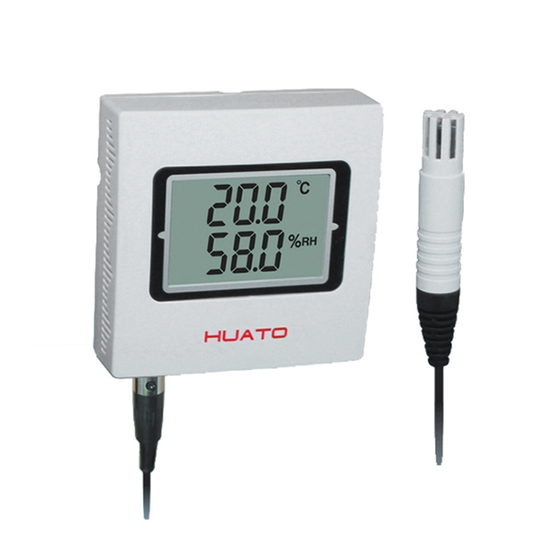
Intr oduc ti on Section 1 - Introduction HE500 series temperature and humidity transmitter adopt Switzerland imported 2 in 1 sensor, the output it provides including voltage, current and modbus .etc. With built-in high performance, lower power SCM, it provides wide range and high precision measurements. -
Page 5: Temperature And Humidity Data Logger Appearance
HE500A-TH M O D E L : H E 5 0 0 A - T H RANGE:-30~70℃/0~100%RH H E 5 0 0 A 2 1 3 8 HUATO SYSTEM CO.,LTD LCD screen Stabilizer of upper and lower covers Label Venting hole... - Page 6 Introduction HE500V5/HE500V10/HE500M/HE500N M O D E L : H E 5 0 0 V 5 RANGE:-0~50℃/0~100%RH H E 5 0 0 A 2 1 3 8 HUATO SYSTEM CO.,LTD LCD screen Stabilizer of upper and lower Label covers Set button...
-
Page 7: Temperature And Humidity Data Logger Screen
Introduction LCD screen Confirm button Screw holes Label (save set data) Threading hole Set button Stabilizer of upper and Collection of thread hole Value up Connection port Lower covers Value down Venting hole External Temperature Humidity Sensor 1.6 - Temperature and Humidity Data Logger Screen Section HE500A-TH/HE500A-EX/HE500V5/HE500V5-EX/HE500V10/ HE500V10-EX/HE500M/HE500M-EX/HE500N/HE500N-EX... -
Page 8: Button Function Instructions
Introduction 1.7 - Button function instructions and button operation Section 1.7.1 - Button function instructions :Press to enter SET mode when the transmitter is in normal displaying mode; Press to get back to normal displaying mode when the transmitter is in SET mode. :Add value (switch symbol) :Reduce value :Press to save temperature value and enter humidity SET mode if the transmitter... - Page 9 Introduction 2, Enter the setting interface and temperature deviation setting Power on the HE500A and press the 【MENU】 key for 2 seconds to enter the setting interface. As shown in Figure (1), the LCD screen displays the set temperature 【SET.T】 and the initial temperature deviation value 【0.0】.
-
Page 10: He500M/N Button Operation Instructions
Introduction F Switch Settings ° ° When the 【MENU】 key is pressed again, the temperature symbol switching interface is entered. At this time, the LCD screen displays the set temperature 【SET. 】 and the °C temperature initial value symbol 【°C】; when the 【UP】/【DOWN】 key is pressed, the current temperature can be changed Symbol [°C] →... - Page 11 M O D E L : H E 5 0 0 A - T H RANGE:-30~70℃/0~100%RH H E 5 0 0 A 2 1 3 8 HUATO SYSTEM CO.,LTD Figure 4 3, Baud rate setting (HE500M) Press the 【MENU】 button again to display the screen display content as shown in Figure (5);...
- Page 12 Introduction Figure 5 Figure 6 Figure 7 Figure 8 Figure 9 4, C / F switch settings Press the 【MENU】 button again, the interface will display as shown in Figure (10), the LCD screen will display the setting temperature 【SET】 and the setting item 【 °C 】. At this time, the default temperature symbol is 【...
- Page 13 Introduction 5, The temperature is too high alarm settings Press the 【MENU】 button again, the interface will display as shown in Figure (11). The LCD screen displays the set temperature 【SET】 and the setting item 【HI】. At this time, the default temperature high alarm threshold is 120.0 and the symbol is 【°C】. Press the 【UP】(【DOWN】) button to perform the 【Add】...
- Page 14 Introduction 7, humidity is too high alarm settings Press the 【MENU】 button again, the interface will display as shown in Figure (13). The LCD screen displays the set temperature 【SET】 and the setting item 【HI】. At this time, the default temperature high alarm threshold is 100.0, and the symbol is 【RH%】, at this time, press the 【UP】...
- Page 15 Introduction 9, temperature and humidity is too high and too low alarm settings Press the 【MENU]】 button again, the interface will display as shown in Figure (15), Figure (16), LCD screen display setting temperature 【 SET 】 and setting items 【 ? 】 , the temperature and humidity are too high and the alarm is too low by default.
-
Page 16: Output Interpretation Table
Introduction 11, Restore factory settings (HE500M) Press 【MENU】 again to enter the factory reset interface. After pressing the 【OK】 button for 3 seconds, the user will restore the factory settings, and then automatically exit the setting interface. The interface display is shown in Figure (19); after pressing the 【MENU】 button, Make the factory settings and exit (Note: The factory reset interface is a separate interface, and the settings of the previous interface are not saved after pressing the 【MENU】... -
Page 17: Section 2 Method Of Cable Installation
Installation and Instruction Section 2 - Method of Cable Installation This section describes the installation methods of each series of HE500 products. The name, meaning and proper wiring of each terminal are described in detail. Section 2.1 - Voltage T_out RH_out Temperature Output Humidity Output... -
Page 18: Modbus/Rs485
Installation and Instruction Section 2.3 - Modbus/RS485 485- 485+ Negative DC Input Positive DC Input... -
Page 19: Installation Size
Installation and Instruction Section 2.4 - Installation Size 70mm 67mm Section 2.5 - Standard MODBUS RTU Data Frames (Modbus ) • Address Function Data Check 8-Bits 8-Bits N x 8-Bits 16-Bits...
Need help?
Do you have a question about the HE500 Series and is the answer not in the manual?
Questions and answers