Table of Contents
Advertisement
Advertisement
Table of Contents

Related Manuals for Extreme Networks Virtual Services Platform 7200 Series


Summary of Contents for Extreme Networks Virtual Services Platform 7200 Series
- Page 1 Installing the Virtual Services Platform 7200 Series 9035364 Rev 03 March 2020...
- Page 2 2017-2020, Extreme Networks All Rights Reserved. Legal Notice Extreme Networks, Inc. reserves the right to make changes in specifications and other information contained in this document and its website without prior notice. The reader should in all cases consult representatives of Extreme Networks to determine whether any such changes have been made.
-
Page 3: Table Of Contents
Chapter 2: New in This Document................... 9 Chapter 3: Hardware Models for VSP 7200 Series............... 10 .................. 14 Power cord types and order codes Chapter 4: Preinstallation Checklist.................. 16 Chapter 5: Installing the Virtual Services Platform 7200 Series......... 18 ....................... 18 Installation checklist ....................... 19 Installation fundamentals ...................... 20... -
Page 4: Chapter 1: About This Document
This section discusses the purpose of this document, the conventions used, ways to provide feedback, additional help, and information regarding other Extreme Networks publications. Purpose This guide provides information and instructions to install the Extreme Networks Virtual Services Platform 7200 Series switches. Conventions This section discusses the conventions used in this guide. - Page 5 Conventions Table 2: Text Conventions Convention Description Angle brackets ( < > ) Angle brackets ( < > ) indicate that you choose the text to enter based on the description inside the brackets. Do not type the brackets when you enter the command.
-
Page 6: Documentation And Training
Data Center products Other resources, like white papers, data sheets, and case studies Extreme Networks offers product training courses, both online and in person, as well as specialized certifications. For details, visit www.extremenetworks.com/education/. Getting Help If you require assistance, contact Extreme Networks using one of the following methods: Extreme Search the GTAC (Global Technical Assistance Center) knowledge base;... -
Page 7: Providing Feedback
579 2826. For the support phone number in your country, visit: www.extremenetworks.com/support/contact Before contacting Extreme Networks for technical support, have the following information ready: • Your Extreme Networks service contract number, or serial numbers for all involved Extreme Networks products • A description of the failure •... - Page 8 About this Document • Broken links or usability issues. If you would like to provide feedback, you can do so in three ways: • In a web browser, select the feedback icon and complete the online feedback form. • Access the feedback form at https://www.extremenetworks.com/documentation-feedback/. •...
-
Page 9: Chapter 2: New In This Document
Chapter 2: New in This Document The following section details what is new in this document. Temperature Sensors Warning and critical threshold values are updated in the document. For more information, see Install a Fan Module on page 34. March 2020 Installing the VSP 7200 Series... -
Page 10: Chapter 3: Hardware Models For Vsp 7200 Series
Chapter 3: Hardware Models for VSP 7200 Series This section lists the VSP 7200 Series hardware. Two additional VSP 7200 Series models are available: these are referred to as Port-Licensed models. By default these models ship with the first twenty-four of the forty-eight 10 Gigabit ports (SFP+ or RJ45), and the first four of the six 40 Gigabit ports, enabled. - Page 11 VSP 7200 Series Description Part numbers • 2 ports (Slot 2, ports 5 and 6) out of the six 40 GbE QSFP+ ports require a port license to be operational. VSP 7254XTQ – copper switch • 48 100 Mbps/1 GbE/10 GbE RJ-45 ports EC7200A2B-E6 and EC7200A2F-E6 Model EC7200x2B-E6 ships...
- Page 12 Hardware Models for VSP 7200 Series VSP 7200 Series Description Part numbers Redundant power supplies Important: Make sure the air flow direction of your power supplies and fan modules match the same direction (either front-to-back or back-to-front). 460 watt AC redundant power •...
- Page 13 Important: Extreme Networks recommends using Extreme SFP, SFP+, QSFP+, and QSFP28 transceivers as they have been through extensive qualification and testing. Extreme Networks will not be responsible for issues related to third party transceivers. • The VSP 7200 Series operates in forgiving mode for SFP, SFP+, and QSFP+ transceivers, which means that the switch will bring up the port operationally when using third party SFP, SFP+, or QSFP+ transceivers.
-
Page 14: Power Cord Types And Order Codes
Hardware Models for VSP 7200 Series - two ports (Slot 2, ports 5 and 6) out of the six 40 GbE QSFP+ ports require a Port License to be unlocked. • Port licensing support on the port licensed VSP 7254XTQ copper switch: - 24 ports (Slot 1, ports 25 to 48) out of the 48 100 Mbps/1 GbE/10 GbE RJ-45 ports require a Port License to be unlocked. - Page 15 Power cord types and order codes Table 5: Power Cords with C14 power supply side connector Order Code Description Region AA0020062E6 Power cord 3.05 m IEC C13 to North America NEMA 5-15P AA0020063E6 Power cord 2.5 m IEC C13 to United Kingdom BS1363 AA0020064E6...
-
Page 16: Chapter 4: Preinstallation Checklist
Chapter 4: Preinstallation Checklist Before you install the VSP 7200 Series, make sure that you complete the tasks in the preinstallation checklist. Important: Make sure the air flow direction of the power supplies and fan modules match the same direction (either front-to-back or back-to-front). Task Description Review the technical specification for... - Page 17 Task Description are missing, contact Extreme Networks support. Make sure that the power cord has the Power cord types and order codes correct country-specific termination. page 14. Prepare the rack. Ensure that there is enough rack space to accommodate a 1RU switch (4.45 cm).
-
Page 18: Chapter 5: Installing The Virtual Services Platform 7200 Series
Chapter 5: Installing the Virtual Services Platform 7200 Series This section provides the information and procedures to install the VSP 7200 Series. Installation checklist Use this checklist to install the VSP 7200 Series. Task Description Mount the VSP 7200 Series in the Installing the switch in an equipment equipment rack. -
Page 19: Installation Fundamentals
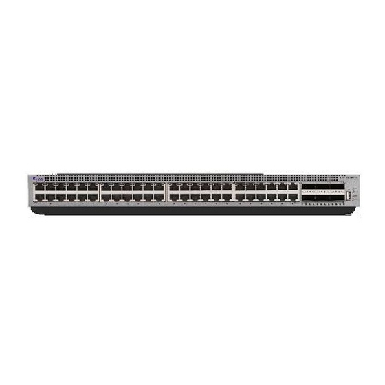
Installation fundamentals Installation fundamentals The VSP 7200 Series has four models: VSP 7254XSQ (fiber) and VSP 7254XTQ (copper) and their port licensed versions. The VSP 7254XSQ consists of forty eight 1/10 GbE SFP/SFP+ ports. The VSP 7254XTQ consists of forty eight 100 Mbps/1 GbE/10 GbE RJ-45 ports. In the port-licensed versions of either of the models, twenty four ports require a port-license to unlock them. -
Page 20: Electrostatic Discharge
Installing the Virtual Services Platform 7200 Series Figure 2: VSP 7200 Series — Rear view 1. Console port 2. Management port — The LEDs are on the bottom of the port. For more information, see Management port LED state indicators on page 39. -
Page 21: Technical Specifications
Technical specifications • Avoid contact between equipment and clothing. The wrist or ankle strap protects only the equipment from ESD voltages on the body; ESD voltages on clothing can still cause damage. • Avoid touching any connector pins. • Do not remove the wrist or ankle strap until the installation is complete. Preventing electrostatic damage in new cable installations With new cable installations, we recommend that you use an ESD discharge cable to reduce the potential for damage from static, that can build up in cables. - Page 22 Installing the Virtual Services Platform 7200 Series Warning: To avoid bodily injury from hazardous electrical shock and current, never remove the top of the device. No user-serviceable components are inside. Table 6: Physical Specifications Height 1.75 in. (4.4 cm) - 1U Width 17.5 in.
-
Page 23: Package Contents
Package contents • An adequate power source is within 6 feet (1.83 meters) of the switch. One 15-amp circuit is required for each power supply. • At least 2 inches (5.08 centimeters) of clearance on the front and back of the switch for ventilation. •... -
Page 24: Installing An Ac Power Supply
Installing the Virtual Services Platform 7200 Series Important: Installing a combination of AC-input and DC-input power supplies in the same chassis is not supported. To install an AC power supply, see Installing an AC power supply on page 24. To install a DC power supply, see Installing a DC power supply on page 29. - Page 25 Installing a power supply Procedure 1. If there is a power supply cover, remove it and save for possible future use. To remove the cover, push the tab on the spring latch to the left and pull on the extraction handle. Important: If you only have one power supply installed, the other slot must be covered to ensure proper ventilation.
- Page 26 Installing the Virtual Services Platform 7200 Series Note: The chassis design prevents an incorrect installation of a power supply. If you insert a power supply upside down, it will not fully insert. 4. Once you install a power supply, you can connect the AC power cord to the power supply on the back of the switch, and then connect the cord to an AC power outlet.
- Page 27 Installing a power supply Figure 4: AC power supply The 800 W AC power supply uses an IEC 60320 C14 AC power cord receptacle. The corresponding AC power cord uses an IEC 60320 C13 connector. The following table describes the regulatory AC power specifications for the VSP 7200 Series switches.
- Page 28 Installing the Virtual Services Platform 7200 Series VSP 7254XTQ Inrush Current: 40 A maximum Turn on Condition: 1 second maximum after application of AC power Important: The output rise time, from 10 to 90 percent, is 50 ms maximum and monotonic under all defined input and output conditions.
-
Page 29: Installing A Dc Power Supply
Installing a power supply Installing a DC power supply Important: Installing a combination of AC-input and DC-input power supplies in the same chassis is not supported. The VSP 7200 Series Series supports two field-replaceable 800 W DC power supplies. One comes with the switch and you can install a second power supply to provide redundancy and load sharing. - Page 30 Installing the Virtual Services Platform 7200 Series Important: If you only have one power supply installed, the other slot must be covered to ensure proper ventilation. If a power supply fails, replace it as soon as you can but leave it in place until you do.
- Page 31 4. Once you install a power supply, use the following steps to connect the DC power supply wiring assembly: a. Extreme Networks supplies a DC power supply wiring assembly to connect the DC power supply to the DC input power source.
- Page 32 Installing the Virtual Services Platform 7200 Series Table 11: DC power supply LED states Color and Status Description There is no DC power to either power supply. Green (steady) There is output and the power supply is operating normally. Green (blinking) The power supply is present, but its output is standby voltage (12VSB).
-
Page 33: Removing A Power Supply
Removing a power supply The following table describes the regulatory DC power specifications for the VSP 7200 Series switch. Note that regulatory power specifications are based on the maximum rated capacity of the power supplies and are not based on typical power consumption, which is typically lower. Table 12: DC power specifications VSP 7254XSQ or VSP 7254XTQ Input Current:... -
Page 34: Install A Fan Module
Installing the Virtual Services Platform 7200 Series Install a Fan Module The VSP 7200 Series comes with three 12–V fan modules for either front-to-back or back-to-front air flow switch cooling. Important: Make sure the air flow direction of your power supplies matches the same direction for your fan modules. - Page 35 Install a Fan Module Table 14: VSP 7254XTQ Sensor threshold values Sensor name Warning threshold Critical threshold PHY1 PHY2 Use this procedure if a fan fails and you have to replace it. Important: All three fan modules must be installed at all times to ensure proper ventilation. If a fan fails, replace it as soon as you can but leave it in place until you do.
- Page 36 Installing the Virtual Services Platform 7200 Series Note: You can hot swap fan modules while the switch is operational. 5. Verify that the fan module is fully seated in the chassis. The spring latch should engage and return to its original position.
-
Page 37: Led State Definitions
LED state definitions LED state definitions The figures and tables in the following sections describe the LEDs on the VSP 7200 Series switch. The tables describe LED operation for a switch that finishes the power-on self-test. Warning: Fiber optic equipment can emit laser or infrared light that can injure your eyes. Never look into an optical fiber or connector port. -
Page 38: 100 Mbps/1 Gbps/10 Gbps Rj-45 Port Led State Indicators
Installing the Virtual Services Platform 7200 Series Label Color and Status Description Green (steady) The second power supply (in either PSU1 or PSU2) is present and operating normally as a redundant power supply (RPS). Amber (steady) A fan module has been removed. -
Page 39: Qsfp+ Port Led State Indicators
LED state definitions Label Color and Status Description Amber (blinking) The port received a remote fault indicator (RFI). Green (steady) The port has established a link. Green (blinking) The port has established a link and there is data activity. Green (slow blinking) The port is administratively disabled. -
Page 40: Enterprise Device Manager (Edm) Representation Of Physical Led Status
Installing the Virtual Services Platform 7200 Series Table 19: Management port LED state indicators Label Color and Status Description Speed The port is operating at the low speed. Amber (steady) The port is operating at mid speed. Green (steady) The port is operating at high speed. -
Page 41: Using The Optional Slide Rack Mount Kit
Installing the switch in an equipment rack • The rack is grounded to the same grounding electrode used by the power service in the area. The ground path must be permanent and must not exceed 1 Ohm of resistance from the rack to the grounding electrode. - Page 42 Installing the Virtual Services Platform 7200 Series Figure 6: Shipping components Rails The following figure shows a slide rail in the default configuration for a 300mm-600mm equipment rack. This configuration comes with the short rear bracket installed. The slide rail actually consists of two separate rails that slide into each other: •...
- Page 43 Installing the switch in an equipment rack Figure 7: Rails Brackets There are three different brackets: • Short rear bracket—The slide rail kit comes with this bracket installed for the 300mm-600mm default configuration. Figure 8: Short rear bracket March 2020 Installing the VSP 7200 Series...
- Page 44 Installing the Virtual Services Platform 7200 Series • Extension bracket—This bracket connects to the rack rail to lengthen it for a 600mm-900mm configuration. • Long rear bracket—This bracket replaces the short rear bracket to modify the slide rail for a 600mm-900mm configuration.
- Page 45 Installing the switch in an equipment rack Figure 10: Thumbscrew lock and release latches • Thumbscrew lock—This feature is on the front end of the chassis rails, and is used to lock the switch in the home position of the equipment rack. Figure 11: Thumbscrew lock March 2020 Installing the VSP 7200 Series...
- Page 46 Installing the Virtual Services Platform 7200 Series • White release latch—This latch is the white, plastic tab on the chassis rails. - When you first install the slide rails, use these latches to disconnect the chassis rail from the rack rail so you can install the chassis rail on the switch.
- Page 47 Installing the switch in an equipment rack Figure 14: Blue locking mechanism - When you first install the slide rails and you fully extended the rail, you can lift the locking mechanism to release the rail so it can slide back into the main part of the unit. - When you install the switch in a rack and then pull the switch out, this mechanism automatically locks the slide rail in a fully extended position.
- Page 48 Installing the Virtual Services Platform 7200 Series • Pin block—The pin block supports equipment racks with different shaped holes. - For racks with square holes, the pin block fits right into the holes in the rack. - For racks with large round holes, the pin block retracts halfway when you insert the rail into the rack.
- Page 49 Installing the switch in an equipment rack Installing slides in a 300mm-600mm equipment rack Use the following procedure to install your switch in an equipment rack with a depth between 300mm and 600mm. Before you begin Note: The Slide Rack Mount Kit is fairly complex due to its versatile design. To make your installation easier, read the Inventory of slide components on page 41 section to familiarize yourself with...
- Page 50 Installing the Virtual Services Platform 7200 Series b. Pull the inner chassis rail and slide it out as far as you can. March 2020 Installing the VSP 7200 Series...
- Page 51 Installing the switch in an equipment rack c. Slide the white release latch in the direction of the arrow stamped on the lock and pull the chassis rail out of the rack rail. 4. Lift the blue locking mechanism on the rack rail to slide the outer section back into the main section.
- Page 52 Installing the Virtual Services Platform 7200 Series 5. Use the following steps to attach the chassis rail to the chassis: a. Orient the chassis rail with the thumbscrew lock towards the front and position the rail over the standoffs on the chassis.
- Page 53 Installing the switch in an equipment rack 6. Use the following steps to secure the rack rails to the frame: a. Orient the rack rail so that the end with the black retaining latch is facing front. b. Adjust the length of the rack rail so it fits the rack depth by loosening the two screws on the rack rail and adjusting the length.
- Page 54 Installing the Virtual Services Platform 7200 Series c. Push the end of the retaining latch out so it opens up. d. Insert the bracket pins into the desired holes in the frame. The pin block accommodates three different rack types. In the default position, the pin block fits into racks with square holes.
- Page 55 Installing the switch in an equipment rack e. Close the retaining latch so that it wraps around the frame and locks into place. f. Repeat the above steps on the rear bracket. g. Repeat these steps for the rack rail on the other side of the frame. 7.
- Page 56 Installing the Virtual Services Platform 7200 Series b. Pull the blue latches on the chassis rails towards the front and slide the switch into the frame. Note: After you install the switch in a rack, slide it out until the lock (shown above) engages.
- Page 57 Installing the switch in an equipment rack Installing slides in a 600mm-900mm equipment rack Use the following procedure to install your switch in an equipment rack with a depth between 600mm and 900mm. Before you begin Note: The Slide Rack Mount Kit is fairly complex due to its versatile design. To make your installation easier, read the Inventory of slide components on page 41 section to familiarize yourself with...
- Page 58 Installing the Virtual Services Platform 7200 Series b. Pull the inner chassis rail and slide it out as far as you can. March 2020 Installing the VSP 7200 Series...
- Page 59 Installing the switch in an equipment rack c. Slide the white release latch in the direction of the arrow stamped on the lock and pull the chassis rail out of the rack rail. 4. Lift the blue locking mechanism on the rack rail to slide the outer section back into the main section.
- Page 60 Installing the Virtual Services Platform 7200 Series 5. Use the following steps to attach the chassis rail to the chassis: a. Orient the chassis rail with the thumbscrew lock towards the front and position the rail over the standoffs on the chassis.
- Page 61 Installing the switch in an equipment rack 6. Remove the two screws and nuts securing the short rear bracket to the rack rail. This bracket is for 300mm-600mm equipment racks only and is not used in this installation. Save the bracket for possible future use. March 2020 Installing the VSP 7200 Series...
- Page 62 Installing the Virtual Services Platform 7200 Series 7. Identify the extension bracket and the long rear bracket. Use these brackets to extend the rack rail for 600mm-900mm racks. March 2020 Installing the VSP 7200 Series...
- Page 63 Installing the switch in an equipment rack 8. Use the countersink screws with the following steps to attach the extension bracket to the rack rail: a. Push the blue release lock up and slide the middle rail out as far as possible. b.
- Page 64 Installing the Virtual Services Platform 7200 Series Note: Using the bag with ten M4 screws, attach the extension bracket to the rack rail by inserting the screws from the rack rail side and then into the extension bracket. The following figure shows the extension bracket attached to the rack rail.
- Page 65 Installing the switch in an equipment rack d. Insert the long rear bracket into the extension bracket assembly. e. Install the first two screws on the end of the long rear bracket. f. Lift the blue locking mechanism and slowly slide the rail back into the main assembly. This exposes a “window”...
- Page 66 Installing the Virtual Services Platform 7200 Series screws one at a time. 9. Use the following steps to secure the rack rails to the frame: a. Orient the rack rail so that the end with the black retaining latch is in the front of the rack.
- Page 67 Installing the switch in an equipment rack c. Push the end of the retaining latch out so it opens up. d. Insert the bracket pins into the desired holes in the frame. The pin block accommodates three different rack types. In the default position, the pin block fits into racks with square holes.
- Page 68 Installing the Virtual Services Platform 7200 Series e. Close the retaining latch so that it wraps around the frame and locks into place. f. Repeat the above steps on the rear bracket. 10. Repeat these steps for the rack rail on the other side of the frame.
- Page 69 Installing the switch in an equipment rack b. Pull the blue release latches on the chassis rails towards the front and slide the switch into the frame. Note: After you install the switch in a rack, slide it out until the lock (shown above) engages. To slide the switch back into the rack, push the blue locks on the chassis rails towards the back and slide the switch into the frame.
- Page 70 Installing the Virtual Services Platform 7200 Series Important notice about rack safety One prerequisite to installing the switch in an equipment rack is to bolt the equipment rack to the floor. Warning: If you pull the chassis all the way out on the slide rails, there is a danger of the rack tipping over if the rack is not bolted to the floor.
-
Page 71: Using The Supplied Brackets
Installing the switch in an equipment rack pulls the chassis out of the rack. Using the supplied brackets This procedure describes how to install the switch in an equipment rack using the supplied brackets. The brackets that come with the chassis are for mounting the unit in a standard 19–inch rack. We recommend that you mount a tray into the rack and set the chassis upon the tray. - Page 72 Installing the Virtual Services Platform 7200 Series 2. Attach a bracket to each side of the switch using a #2 Phillips screwdriver as illustrated below. 3. Slide the switch onto a shelf or tray in the rack. 4. Insert and tighten the rack-mount screws.
-
Page 73: Cable Requirements For The Vsp 7200 Series
The following sections describe how to install and remove transceivers in the VSP 7200 Series switch. In this context, the term transceiver refers to Small Form Factor Pluggable (SFP), SFP+, and Quad 4-channel SFP (QSFP+). For more information about transceiver use and designation, see Extreme Networks Pluggable Transceivers Installation Guide. Installing transceivers Install transceivers by performing this procedure. -
Page 74: Console Port Pin Assignments
Installing the Virtual Services Platform 7200 Series Removing transceivers Remove transceivers by performing this procedure. 1. Disconnect the network fiber cable from the transceiver. 2. Use the locking mechanism on the transceiver to release it. The locking mechanism varies from model to model as illustrated below. -
Page 75: 40Gbase-Qsfp+ Ports
40GBASE-QSFP+ ports Connector Pin Number Signal Receive data (RXD) — mandatory Data set ready (DSR) — optional Clear to send (CTS) — optional, can swap or link with pin 1 40GBASE-QSFP+ ports When a port is channelized, only break out cables (copper or active optical DAC) should be used in it. - Page 76 Installing the Virtual Services Platform 7200 Series SysDescr : VSP-7254XTQ (w.x.y.z) SysName : VSP-7254XTQ SysUpTime : 0 day(s), 00:07:56 SysContact : http://www.extremenetworks.com/contact/ SysLocation : 9 Northeastern Blvd,Salem,NH. 03079 Chassis Info: Chassis : 7254XTQ ModelName : 7254XTQ BrandName : Extreme Networks.
- Page 77 Viewing hardware information Port Lock Info : Status : off LockedPorts Message Control Info : Action : suppress-msg Control-Interval Max-msg-num Status : disable Configuration Operation Info Since Boot Up: Last Change: 0 day(s), 00:02:49 Last Vlan Change: 0 day(s), 00:02:41 Last Statistic Reset: 0 day(s), 00:00:00 Current Uboot Info : ----------------------------------------------------------------------------------------------------...
-
Page 78: Chapter 6: Translations Of Safety Messages
Chapter 6: Translations of safety messages Caution: When you mount this device in a rack, do not stack units directly on top of one another. You must secure each unit to the rack with appropriate mounting brackets. Mounting brackets cannot support multiple units. Caution: Achtung: Wenn diese Einheit in einem Rack montiert wird, muß... - Page 79 Caution: If you are not installing a module in the slot, be sure to keep the metal cover plate in place over the slot. Removing the cover plate impedes airflow and proper cooling of the unit. Caution: Achtung: Wenn Sie kein Modul im Schacht verwenden, muß die Metallabdeckung über dem Schacht montiert sein.
- Page 80 Translations of safety messages Warning: Disconnecting the AC power cord is the only way to turn off AC power to this device. Allow at least 30 seconds for the this device to fully power down before restoring power. Otherwise, this device might produce a core file during the reset leading to an extra delay during boot time.
- Page 81 Danger: Warning: The lithium battery is not field replaceable. It should be removed and replaced by authorized personnel only. Contact Extreme Networks Technical Support for assistance if the battery requires replacement. March 2020 Installing the VSP 7200 Series...
Need help?
Do you have a question about the Virtual Services Platform 7200 Series and is the answer not in the manual?
Questions and answers