Table of Contents
Advertisement
Advertisement
Chapters
Table of Contents

Related Manuals for Securiton SecuriFire 500

Summary of Contents for Securiton SecuriFire 500
- Page 1 SecuriFire 500 fire detection system System description...
-
Page 2: Table Of Contents
Components of the SecuriLine eXtended Programming and software Projection Loop configuration Object texts Download / Upload Service Tools 8.1.1 ServiceMonitor 8.1.2 ServiceCenter 8.1.3 SystemInformation 8.1.4 LoopAnalysis 8.1.5 Virtual MIC List of figures 2 / 18 SecuriFire 500, System Description, T 811 058 en... -
Page 3: The Securifire System Family
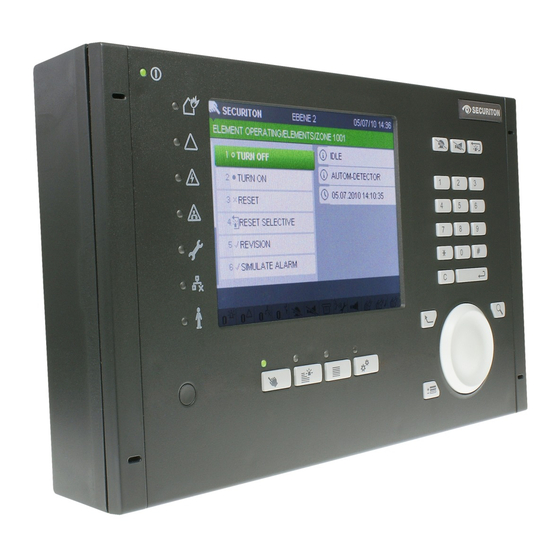
Compact one-loop system control panel • For the connection of up to 250 elements • Integrated IP interface • Intuitive operation thanks to integrated SecuriFire MIC Fig.1 SecuriFire FCP 500 SecuriFire 500, System Description, T 811 058 en 3 / 18... -
Page 4: The System Concept
SecuriFire FCP 500 fire alarm control panel SecuriFire 500 is a stand-alone fire alarm control panel and is suitable for connecting a SecuriLine eXtended addressable loop with up to 250 participants. The control panel is equipped with all the necessary interfaces for connection to the fire brigade. It also has relay outputs and a connection for the external device bus. -
Page 5: Securilan
Simple to operate configuration and commissioning tools • Event memory for 10,000 messages in real time • Comprehensive, integrated overvoltage protection concept Fig.3 Topology of a SecuriFire 500 fire alarm control panel SecuriFire 500, System Description, T 811 058 en 5 / 18... -
Page 6: Key Features At A Glance
3 Inputs, outputs, repeat signals, Detection zones max. 250 External (e.g. sprinkler systems) max. 250 Delay layers max. 16 Customer-specific texts 6,500 if average is 25 characters per element 6 / 18 SecuriFire 500, System Description, T 811 058 en... -
Page 7: Display, Operation And Indication
It includes a 5.7’’ TFT colour display for displaying all system states in plain text. No labelling on the front of the housing (only display elements). Intuitive operation with operating elements and SecuriWheel. SecuriFire 500, System Description, T 811 058 en 7 / 18... -
Page 8: External Device Bus
It is used for displaying functions, messages and states. The display uses 32 LEDs (red and yellow; programmable) and has 1 green operation indicator. Insertion stripes are used to label the LEDs. Fig.6 B5-EPI-PIM 8 / 18 SecuriFire 500, System Description, T 811 058 en... -
Page 9: 3.2.1.2 B5-Epi-Pcm Partial Indication And Control Map
3.2.1.6 B5-EPI-FPD Fire brigade control board according with DIN 14661 The B5-EPI-FPD is compliant with DIN 14661 for indicating operating states and for standardised operation of a fire alarm control panel by fire brigade personnel. Fig.11 B5-EPI-FPD SecuriFire 500, System Description, T 811 058 en 9 / 18... -
Page 10: 3.2.1.7 B5-Epi-Fpcz Fire Brigade Panel For The Czech Republic
The B5-EPI-FPS-S is compliant with SS3654. Displays the relevant operating states to ensure simple operation by the fire brigade. Display message and labels are in Swedish language. Fig.13 B5-EPI-FPS-S 10 / 18 SecuriFire 500, System Description, T 811 058 en... -
Page 11: Housing Variants And Expansion Options
Also, the charge curves of the batteries must exactly match the power supply unit in use. The installation location for the batteries is on the housing base of each SecuriFire FCP. Two 7 Ah batteries connected in se- ries are always used. SecuriFire 500, System Description, T 811 058 en 11 / 18... -
Page 12: Securiline Extended
Programming and commissioning the SecuriLine eXtended is performed exclusively with the SecuriFire Studio software. A cal- culation program is included for computing the maximum possible ring circuit length based on the connected elements and the wire cross-section in use. 12 / 18 SecuriFire 500, System Description, T 811 058 en... -
Page 13: Key Features At A Glance
• max. 250 physical elements per SecuriLine eXtended • max. 63 detectors per detection zone • max. 1 repeat signal per detector • max. 3’500 m ring circuit length SecuriFire 500, System Description, T 811 058 en 13 / 18... -
Page 14: Components Of The Securiline Extended
EN 54-11; the MCP 545X is a type A (direct triggering) device. It is available in red and other col- ours and designs (protection class etc.). Fig.23 MCP 545 X N 14 / 18 SecuriFire 500, System Description, T 811 058 en... -
Page 15: Fig.24 Mcp 535
In the event of the loss of loop voltages an "Active in Fail-Safe-Position" can be programmed separately for each output. Fig.31 BX-O1 SecuriFire 500, System Description, T 811 058 en 15 / 18... -
Page 16: Fig.32 Bx-I2
The BX-ESL determines the position of the activation pin. The state active/passive is reported to the FAS and indicated on the BX-ESL by means of a LED. Fig.33 BX-ESL 16 / 18 SecuriFire 500, System Description, T 811 058 en... -
Page 17: Programming And Software
All program components are stored in the B7-CPB main control board; during startup they are distributed to all computer com- ponents. All necessary software components are provided in SecuriFire Studio, which contains all of the necessary planning, commissioning, maintenance and diagnostic data of the SecuriFire system. For SecuriFire 500 an easy start up assistant “EasyConfig SF500”... -
Page 18: Service Tools
Ethernet-based connection (TCP/IP). That way, operating the fire alarm control panel from a porter's loge or a reception desk ideally complements the existing building services. 18 / 18 SecuriFire 500, System Description, T 811 058 en... -
Page 19: List Of Figures
Fig.1 SecuriFire FCP 500 ..................................3 Fig.2 Overvoltage protection ................................... 4 Fig.3 Topology of a SecuriFire 500 fire alarm control panel ........................5 Fig.4 SecuriFire FCP with built-in B7-MIC11 indication and control map ....................7 Fig.5 Schematic of an EPI-BUS ................................8 Fig.6 B5-EPI-PIM .................................... - Page 20 Securiton AG, Alarm and Security Systems www.securiton.com, info@securiton.com Securiton d.o.o., Serbia www.securiton.rs, info@securiton.rs Securiton Kft., Hungary www.securiton.hu, info@securiton.hu Securiton (M) Sdn Bhd. Malaysia www.securiton.com, asia@securiton.com.my Securiton RUS, Russia www.securiton.ru, info@securiton.ru A company of the Swiss Securitas Group...
Need help?
Do you have a question about the SecuriFire 500 and is the answer not in the manual?
Questions and answers