LK Systems ICS.2 Series Assembly Instructions Manual
Room temperature control
Hide thumbs
Also See for ICS.2 Series:
- Assembly instructions manual (25 pages) ,
- Assembly instructions manual (6 pages)
Advertisement
Quick Links
LK Room Temperature Control ICS.2
Design
LK Room Temperature Control ICS.2 is a con-
trol system designed for LK Underfloor Heat-
ing. The system is suitable for small, medium or
large building installations. LK ICS.2 has been
designed to provide high levels of comfort and
energy efficient heating systems thanks to its ad-
vanced self-modulation technique.
The system consists of LK Receiver ICS.2,
LK Room Thermostat ICS.2 and LK Actuators 24 V.
Communications between the room thermostat
and the receiver can either be wireless or wired.
The receiver is available in versions for 1-channel
and 8-channels. The receiver with 1 channel can
communicate with 1 room thermostat. The receiver
with 8 channels can communicate with 1 to 8 room
thermostats. The receiver with 8 channels can com-
bine both wireless and wired communications.
If the system consists of more than one receiver,
the units can communicate wirelessly with each
other in order for common functions to work.
This includes controlling the circulation pump,
heat source, the ability to connect the system (LK
Webserver) to the Internet.
LK ICS.2 includes a variety of smart features such
as adaptive week programming, holiday func-
tions, fire place function, the capability to connect
to an remote sensor. By using the LK Webserver
accessory, you can control your heating system
via the Internet from a mobile phone, tablet or
computer.
L K ICS.2 can communicate via Mod-
bus protocol RS-485/RTU for connecting to the
property controller.
Assembly instructions | LK Room Temperature Control ICS.2
Function
The room thermostat controls the temperature
in each room (zone) via wireless or wired signal
transmission to the receiver. The actuators for
each room/zone are operated via the receiver.
Self-modulation technique
In order for your underfloor heating to be con-
trolled as energy efficiently as possible, LK ICS.2
works with a self-modulation technique. The self-
modulation technique means that the flow in the
floor heating circuits is continuously optimised
based on the needs of the room and thereby pro-
vides better comfort and a more energy efficient
and environmentally smarter underfloor heat-
ing system compared to systems with traditional
ON/OFF technology.
The features the system offers include the fol-
lowing:
• Self-modulation technique
• Access from internet via the LK Webserver
accessory*
• Room thermostat in high gloss white, high
gloss black or silver grey
• Adaptive week program
• Holiday function
• Logging/analysis function*
• Wired or wireless communication between
room thermostat and receiver*
• Valve exercising function
• Pump logics*
• Control of heat source*
• Fireplace function
• By-pass function
• Temperature range limits
* Applies to LK Receiver 8 ICS.2
EN.33.C.152.1911
1 (25)
Advertisement

Related Manuals for LK Systems ICS.2 Series


Summary of Contents for LK Systems ICS.2 Series
- Page 1 Assembly instructions | LK Room Temperature Control ICS.2 LK Room Temperature Control ICS.2 Design Function The room thermostat controls the temperature LK Room Temperature Control ICS.2 is a con- in each room (zone) via wireless or wired signal trol system designed for LK Underfloor Heat- transmission to the receiver.
- Page 2 Assembly instructions | LK Room Temperature Control ICS.2 Assembly instructions ICS.2 Room thermostat temperature mea- surement Requirements In order to achieve accurate room temperature The requirements for a properly functioning un- measurement it is important to prevent draft be- derfloor heating system is a weather-controlled hind the thermostat.
- Page 3 Assembly instructions | LK Room Temperature Control ICS.2 Setup for room thermostats and receivers General When setting up a system, the constituent receiv- ers must be defined as the Master unit or Slave unit depending only on the size of the system. A network-connected system may consist of a max- imum of one Master unit and seven Slave units.
- Page 4 Assembly instructions | LK Room Temperature Control ICS.2 Confirm the setup of the Master unit by pressing The picture shows a Slave unit that has been allocated the L button once. This turns off all lights and order number 2. concludes the Master unit setup.
- Page 5 Assembly instructions | LK Room Temperature Control ICS.2 Hold the L button in until the L light is solid When all slave units have been programmed, green on the receiver that the room thermostats the setup is completed by pressing the are to undergo the setup process for.
- Page 6 Assembly instructions | LK Room Temperature Control ICS.2 Once synchronisation is complete, the room thermostat shows standard mode with room temperature and other information. This con- firms that the setup is complete. The L light changes to orange and the channel Worth knowing: lights change to green.
- Page 7 LK Webserver LK Room Temperature Control ICS.2 communi- cates “point to point” with the network's BMS. LK Systems provides on request documenta- tion that describes the communication protocol, which makes it possible to control/read all of the system's features via Modbus.
- Page 8 Assembly instructions | LK Room Temperature Control ICS.2 LK Receiver 8 ICS.2 MEM input The receiver is fitted with a MEM input (USB type A) that is primarily used when you need to log into the system. Measurement data is sent to the LK ICS MEM Stick once a minute.
- Page 9 Assembly instructions | LK Room Temperature Control ICS.2 LK Receiver 8 ICS.2, overview 9 10 FUSE 230VAC PUMP BOILER SETBACK 14 13 12 LK Receiver 8 ICS.2 Name Description U button Used if the unit software needs updating. A button Used in combination with other buttons to enable alternative functions.
- Page 10 Assembly instructions | LK Room Temperature Control ICS.2 Pump Relay Boiler Relay Receiver 8 has a potential-free pump relay for It is possible to control the system’s heat source controlling the system's circulation pump, for via the unit’s boiler relay. The relay is located un- example a pump in a shunt unit.
- Page 11 Assembly instructions | LK Room Temperature Control ICS.2 LK Receiver 1 ICS.2 The LK Receiver 1 ICS.2 has 1 channel which means that maximum 1 LK Room Thermostats ICS.2 can be assigned/connected to the unit. The Receiver collects data from the room thermo- stat and sends control signals to the LK Actua- tors.
- Page 12 Assembly instructions | LK Room Temperature Control ICS.2 LK Room Thermostat ICS.2 Functional Description LK Room Thermostat ICS.2 is available as a ver- sion where the communication between the room thermostat and the receiver is wireless as well as in a wired version where the communication be- tween the room thermostat and the receiver takes place via a two-wire cable.
-
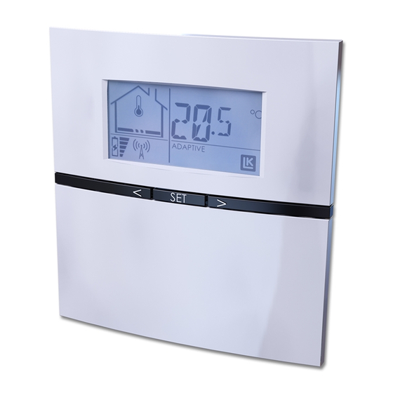
Page 13: Description Of Display
Assembly instructions | LK Room Temperature Control ICS.2 Description of display 1. Heat on/off and MIN and MAX limit 2. Number on receiver and error code 3. Room temperature measurement enabled 4. Indicates constantly disconnected week program 5. Temperature indication 6. - Page 14 Assembly instructions | LK Room Temperature Control ICS.2 Description of the room thermostat's menus/settings There are a number of abbreviations under the room thermostat setup menu . The table below shows the abbreviation and its meaning. The room thermostat setup menu is accessed by holding down the SET button until flashes, confirm with SET.
- Page 15 Assembly instructions | LK Room Temperature Control ICS.2 Settings/functions Holiday function – enable The function is enabled from any room thermo- Setback (central temperature reduction) stat as follows: The LK Receiver 8 ICS.2 is fitted with a setback input. Enabled contact (closed contact) 1.
- Page 16 Assembly instructions | LK Room Temperature Control ICS.2 Week program Week program – temperatures The unit is fitted with a week program. The week The units are delivered by default with the fol- program switches between either Comfort (day lowing values: temperature) or Economy (night setback).
- Page 17 Assembly instructions | LK Room Temperature Control ICS.2 Week program – adaptive function Time & date The unit is fitted with a system clock. In order The system has an adaptive function which for the week program to work, the unit's system means that the system learns the level of thermal clock must be set.
- Page 18 Assembly instructions | LK Room Temperature Control ICS.2 Button lock Fireplace function It is possible to lock the room thermostat buttons This function is designed to be used when you re- to prevent unauthorised users from changing the quire high comfort on your floor even though the room is already heated, for example, when you room thermostat settings.
- Page 19 Assembly instructions | LK Room Temperature Control ICS.2 Time-controlled bypass keeps the bypass circuit The external sensor, LK External Sensor ICS/S2 is open for 22 minutes, then turns the circuit off. connected as follows: 1. The external sensor is to be installed in a The By-pass function is enabled as follows: protective pipe, see separate instructions 1.
-
Page 20: Battery Replacement
Assembly instructions | LK Room Temperature Control ICS.2 Floor symbol flashing = floor temperature only, LK EPS 16 no effect from the room sensor. Confirm with Set. Position a conduit along the long side of the floor The internal sensor is inactive. heating installation so that it is pointing towards the nearest short side. -
Page 21: System Restrictions
Assembly instructions | LK Room Temperature Control ICS.2 System restrictions Below is a summary of system restrictions which should not be exceeded. Restriction Note Number of room thermostats per receiver 8 ICS.2 Number of actuators per Receiver unit 8 ICS.2 Number of room thermostat per Receiver unit 1 ICS.2 Number of actuators per Receiver unit 1 ICS.2 Number of actuators per channel... - Page 22 Assembly instructions | LK Room Temperature Control ICS.2 Follow the instructions below to erase individual Following a reset, the receiver can be re-pro- room thermostats directly from its receiver: grammed to the network. Note: If the reset unit was a Master unit in the 1.
- Page 23 Assembly instructions | LK Room Temperature Control ICS.2 The network in the example above consists of a total of three programmed receiver units, one of which is the Master. The unit that has been checked has order number 2 in the network. The network can be extended with five receivers to a total of 8 units.
- Page 24 Assembly instructions | LK Room Temperature Control ICS.2 Table of error codes RU = Receiver unit RT = Room thermostat Error RT indi- RU indicates Description Things to do Comment code cates 01 ERR Red light on the af- No communication Check the signal path, antennas fected channel light has taken place in 60...
-
Page 25: Technical Data
No condensation ing storage Energy declaration Energy declaration in accordance with EU 811/2013 Temperature regulator's class Temperature regulator's contribution to the season's mean efficiency of room heating EN.33.C.152.1911 LK Systems AB, Box 66, 161 26 Bromma, Sweden | www.lksystems.se 25 (25)
Need help?
Do you have a question about the ICS.2 Series and is the answer not in the manual?
Questions and answers