Table of Contents
Advertisement
Quick Links
®
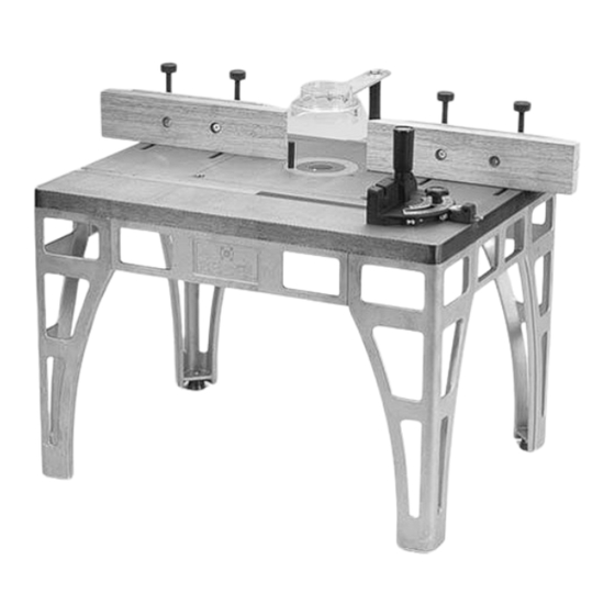
ROUTER TABLE
ITEM W2000
OPERATING MANUAL
P.O. Box 2309
Bellingham, WA 98227
COPYRIGHT © 1995 BY WOODSTOCK INTERNATIONAL, INC., REG.# TX 3 360-515
WARNING: NO PORTION OF THIS MANUAL MAY BE REPRODUCED IN ANY SHAPE
OR FORM WITHOUT THE WRITTEN APPROVAL OF WOODSTOCK INTERNATIONAL, INC.
PRINTED IN TAIWAN
REPRINTED FEBRUARY 1999
Advertisement
Table of Contents

Related Manuals for Woodstock The Rebel W2000

Summary of Contents for Woodstock The Rebel W2000
-
Page 1: Router Table
OPERATING MANUAL P.O. Box 2309 Bellingham, WA 98227 COPYRIGHT © 1995 BY WOODSTOCK INTERNATIONAL, INC., REG.# TX 3 360-515 WARNING: NO PORTION OF THIS MANUAL MAY BE REPRODUCED IN ANY SHAPE OR FORM WITHOUT THE WRITTEN APPROVAL OF WOODSTOCK INTERNATIONAL, INC. -
Page 2: Table Of Contents
SAFETY ...16 GENERAL OPERATIONS ...16 STRAIGHT EDGE SHAPING...17 MITER GAUGE WORK ...17 FREEHAND WORK ...18 USING STOP BLOCKS...20 MAINTENANCE ...21 PARTS BREAKDOWN...22 VII. PARTS LIST...23 WARRANTY AND RETURNS ...24 VIII. TABLE OF CONTENTS ® ...3 W2000 Rebel ® – 1... -
Page 3: Introduction
AVOID DANGEROUS ENVIRONMENTS. Do not use power tools in damp or wet loca- tions or expose them to rain. Keep your work area well lighted. 2 – W2000 Rebel ® I. Introduction Keep fingers away from rotating cutters •... -
Page 4: Additional Safety Rules For The Rebel
Make sure that all fasteners used in assembly have not vibrated loose. A starting pin or starting block must be used when shaping irregular workpieces. ® W2000 Rebel ® – 3... -
Page 5: Commentary
But owing to Woodstock’s policy of continuous improvement, changes to the Model W2000 may occur at any time with no obligation on the part of Woodstock. Should you receive a manual update, please insert it into the manual and keep it for reference. -
Page 6: Unpacking
1 Bolt Bag Contents of the bolt bag. Size: Qty: '' - 28 x '' - 28 x 10 - 32 x 10 - 32 '' - 20 '' - 20 x 1 '' - 18 x W2000 Rebel ® – 5... -
Page 7: Ii. Assembly
Step 4 - Attach the feet to the legs. Figure 3. Step 5 - Turn the stand assembly over and move on to the next section. 6 – W2000 Rebel ® II. Assembly ®... -
Page 8: Fence
For maximum safety and support, adjust the wood facings as close to the router bit as possible. Check clearance before start- ing the router. Figure 5. Attaching the wood facing. W2000 Rebel ® – 7... -
Page 9: Safety Guard
Step 4 - Slide the slotted end of the safety guard arm under the washer and tighten the hex head bolt. Figure 7. 8 – W2000 Rebel ® ⁄ "- Figure 7. Safety guard installed. -
Page 10: Electrical Switch (Optional)
Step 1 - Remove the existing router sub-base that is frame. Remove any Figure 11. Removing sub-base from router. ® frame may F. Mounting the Router ® is very easy. attached to your router base. Figure 11. W2000 Rebel Grounding Ring Terminals ® you must ® – 9... -
Page 11: Wiring The Router
Figure 13. Figure 13. Drill and counter sink insert. 10 – W2000 Rebel ® Your existing sub-base mounting screws may be too short to safely secure your router to the table insert. -
Page 12: Iii. Adjustments
Step 3 - Repeat this procedure for the other three corners. Step 4 - Re-check each corner and make fine adjust- ments if necessary. Once the insert is level, tighten down all four jam nuts. Figure 15. Checking insert for flushness. W2000 Rebel ® – 11... -
Page 13: Fence Adjustment
Figure 16. Figure 16. Gauge position of infeed fence with a sample piece of wood. 12 – W2000 Rebel ® For applications where the entire edge of the work- piece is being shaped, the outfeed fence must be offset by the same amount of material that you are removing. -
Page 14: Safety Guard
All hold downs and other safety devices must be used correctly so they will work as intended. Figure 19. Safety guard adjusted properly. ⁄ " hex bolt. Center the safety ® table. W2000 Rebel ® – 13... -
Page 15: Miter Gauge
Step 4 - Push in the miter gauge stop pin. Step 5 - Loosen the jam nut on the stop bolt. 14 – W2000 Rebel ® Step 6 - Adjust the 90° miter gauge stop bolt so it rests against the pin. -
Page 16: Iv. Operations
® is 17" tall, so the ® in a position that will ® directly to the table surface. ® ® . Mount The Rebel to the work W2000 Rebel ® ® – 15... -
Page 17: Safety
These hold-down devises include spring- loaded pressure wheels and feather boards. Figure 21 and 22. Figure 21. Pressure rollers. 16 – W2000 Rebel ® Figure 22. Feather board. When adjusting the fence, replacing router bits or performing any maintenance or inspection,... -
Page 18: Straight Edge Shaping
Ensure that the face piece is long enough to support the end of the workpiece but not so long that it won’t slide past the router bit. Figure 23. Using the miter gauge. W2000 Rebel ® – 17... -
Page 19: Freehand Work
Secure your workpiece with blocks, screws or wedges. If using screws, make sure they don’t protrude through the finish face of your workpiece. 18 – W2000 Rebel ® The workpiece should rest flat on the surface of the table and must not chatter inside the jig. There are a... - Page 20 Slide the work- piece smoothly past the guide bearing. There is a tremendous cutting force on the work- piece. Fixtures must be stable, solid and designed for safety. Please follow all recommended safety procedures. W2000 Rebel ® – 19...
-
Page 21: Using Stop Blocks
Test your setup with a scrap piece of wood and adjust if necessary. Once the stop blocks are properly adjusted, it is a sim- ple matter to produce consistent, multiple cuts. 20 – W2000 Rebel ®... -
Page 22: Maintenance
Failure to do so may result in serious personal injury. ® table. ® should W2000 Rebel ® – 21... -
Page 23: Vi. Parts Breakdown
VI. Parts Breakdown 22 – W2000 Rebel ®... -
Page 24: Vii. Parts List
SCALE GUIDE STUD STOP PIN STOP BLOCK FLAT HEAD SCREW 10-20 X MITER BAR HEX NUT 10-32 FLAT HEAD SCREW "-28 X SMALL INSERT LARGE INSERT STARTING PIN ALUMINUM INSERT CAP SCREW "-28 X 1'' W2000 Rebel ® – 23... -
Page 25: Warranty And Returns
This is Woodstock’s sole written warranty and any and all warranties that may be implied by law, including any merchantability or fitness, for any particular purpose, are hereby limited to the duration of this writ- ten warranty.
Need help?
Do you have a question about the The Rebel W2000 and is the answer not in the manual?
Questions and answers