
Summary of Contents for Bozzio Joysteer Generation 2.0
- Page 1 Bozzio AG Universal System Manual EN_Universal_System_Manual_2_V15-190131.docx Aarbergstrasse 5 2560 Nidau Switzerland...
-
Page 2: Table Of Contents
MMI: Gas-/ brake Tilter ....................34 MMI: 2 way joystick ....................34 5.10 MMI: Basic sensor unit brake .................35 5.11 MMI: Basic sensor unit gas ..................35 5.12 Gas- / brake sensor adjustment ................35 BACKUP-BATTERY .....................36 Bozzio AG * joysteer® page 2 of 56... - Page 3 8 shaped brackets ....................42 Instructor Plug Kit ....................43 SAFETY INFORMATION ....................44 FUNCTIONAL TEST .....................45 ANNEX 1: SYSTEM ERROR MESSAGES AND TROUBLESHOOTING ....46 DOCUMENT INFORMATION ..................55 11.1 Fundamentals ......................55 11.2 Document history ....................55 Bozzio AG * joysteer® page 3 of 56...
-
Page 4: General
This document applies to the joysteer® system generation 2.0. The main change from generation 1.0 to generation 2.0 is as following: Display module Alarm module joysteer® generation 2.0 joysteer® generation 1.0 Bozzio AG * joysteer® page 4 of 56... -
Page 5: Disclaimer
Universal System Manual Disclaimer Bozzio AG refuses their product liability if one or more of the following facts are given: • Driving the system by users who do not possess an appropriate driving licence Exception: driving accompanied by an authorized driving instructor •... -
Page 6: System
MMI or with the J-PAS function. Driving with System OFF is not allowed! The J-PAS Parameters has to be set in such a way that the steering wheel returns to zero at all the time. Bozzio AG * joysteer® page 6 of 56... -
Page 7: System Overview
Universal System Manual System overview CAN- Adapter Important: The backup-battery is not included in joysteer® s delivery pack (storage and security aspects). Bozzio AG * joysteer® page 7 of 56... -
Page 8: Service And Repairs
Nominated car adaption companies are not allowed to repair any modules. Exchanging of modules can only be carried out by the nominated car adaptation company. Exception: EnergyAlarm module: This module contains electrical fuses. Nominated car adaption companies are allowed to change these. Bozzio AG * joysteer® page 8 of 56... -
Page 9: Basic Assembly Group
The housing needs to be grounded by connecting it to the vehicle chassis. If this is done with a cable, its cross section must be at least 2.5 mm . The cable is to be as short as possible. Bozzio AG * joysteer® page 9 of 56... - Page 10 20 A BOARD-BACKUP Connection 30 A BOARD: Steering converter 30 A BACKUP: Steering converter 10 A BOARD: Steering sensor 10 A BACKUP: Steering sensor Diagram above: Layout of fuses within the EnergyAlarm module Bozzio AG * joysteer® page 10 of 56...
-
Page 11: Converter Module Steer, Brake
The housing needs to be grounded by connecting it to the vehicle chassis. If this is done with a cable, its cross section must be at least 2.5 mm . The cable is to be as short as possible. Bozzio AG * joysteer® page 11 of 56... -
Page 12: Cable Harness
The shielding of the cable harness has to be grounded by connecting it to the vehicle chassis. Important: The cable harness is not allowed to be modified at all. Bozzio AG * joysteer® page 12 of 56... -
Page 13: Can Adapter
Adapter. For safety reasons, the shutdown behaviour is confirmed with a button, operated by the user. The detailed description for installation can be found in the enclosed description with the CAN Adapter. Bozzio AG * joysteer® page 13 of 56... -
Page 14: Steering Actuator Module (Sam)
8. Install the airbag and the foot space cover according to the vehicle producer’s specifications 9. Check: the rotation of the steering wheel needs to be uniform and with low force within the complete rotation range Bozzio AG * joysteer® page 14 of 56... - Page 15 Please contact the system provider if turning the steering wheel remains too heavy. The Parameters of the J-PAS Function has to be set such as the steering wheel returns back to zero at any time. Bozzio AG * joysteer® page 15 of 56...
-
Page 16: Brake Actuator Module (Bam)
After installation of the brake actuator module the pedals need to be protected against accidental pushing/ operation or jamming of the user’s feet. Suitable covering is not included in the delivery pack. Bozzio AG * joysteer® page 16 of 56... -
Page 17: Pulse Test Box
Following the provided plug (type "Super Seal") is to be placed according to the schematic below. Puls Test Box Adjust length X 331 10mm 10mm 125 A Backup Battery Important: Both 10mm cables are not to be shortened nor lengthened. Bozzio AG * joysteer® page 17 of 56... -
Page 18: Display Module
The housing needs to be grounded by connecting it to the vehicle chassis. If this is done with a cable, its cross section must be at least 2.5 mm . The cable is to be as short as possible. Bozzio AG * joysteer® page 18 of 56... -
Page 19: Steering Sensor Module
The housing needs to be grounded by connecting it to vehicle chassis. If this is done with the cables, the cable cross section must be at least 2.5 mm . The cables are to be as short as possible. Bozzio AG * joysteer® page 19 of 56... -
Page 20: Smartgas2
Universal System Manual 4.10 SmartGas2 See universal and car specific SmartGas2 manual. Bozzio AG * joysteer® page 20 of 56... -
Page 21: Software And Servicemanager
3. Computer with installed M16C flasher (please contact Bozzio AG) Important: The M16C flasher has to be installed and released by Bozzio. The dealer is not allowed to transfer the installation to other computers. There is a risk to completely and definitively erase the controller Operating System. - Page 22 Install_SteeringSystem2 = Converter S2 • Install_EnergySystem = EnergyAlarmModule EAM 13. The programming will start automatically. 14. When it is done (after about 1 minute) repeat the programming for all other modules (step 11-13). Bozzio AG * joysteer® page 22 of 56...
- Page 23 By using the Servicemanager a system can be parameterised and the system status can be analysed. This is only possible after the complete joysteer® system has been installed. Bozzio AG * joysteer® page 23 of 56...
-
Page 24: Mmi's (Men Machine Interface)
180° and tightening the screws again. The hand rest’s height can be adjusted according to the user’s request. Bozzio AG * joysteer® page 24 of 56... -
Page 25: Mmi: Two Hand Joystick
Loctite 243. This is the set point for fracture for the airbag deployment. 5. Mount to the swivel heads with lock nuts. Secure with Loctite 243 For demo vehicles it is recommended to make the rods extendable in length. Bozzio AG * joysteer® page 25 of 56... -
Page 26: Mmi: Gas-/Brake Slide
1. Rotation of the gas-/ brake slide (front to back) by 180° around its vertical axis 2. Unscrew the lid with handle and rotate by 180° around its vertical axis again (lid and handle are therefore in their original position). 3. Remount the cover Bozzio AG * joysteer® page 26 of 56... -
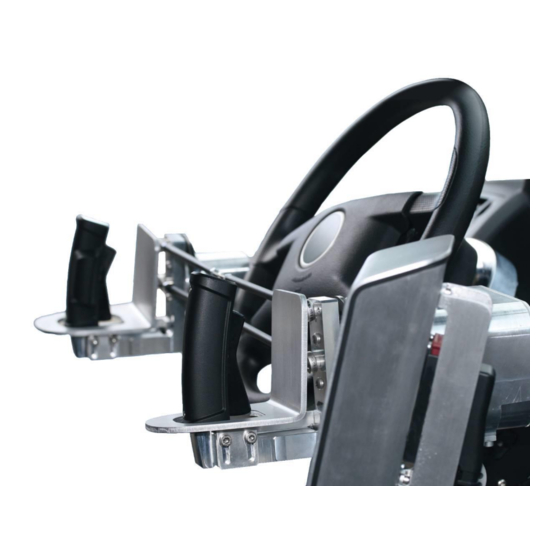
Page 27: Mmi: Handlebar
Universal System Manual MMI: Handlebar MMI: Handlebar with gas/brake MMI: Handlebar “steer only” The installation is always carried in combination with a cantilever. The steering sensor module is installed inside the cantilever. Bozzio AG * joysteer® page 27 of 56... - Page 28 Depending on the combination the basic sensor unit gas or basic sensor unit brake requires to be adjusted (see images below). Ensure that the washers and the circlips are placed properly. Basic sensor unit brake Bozzio AG * joysteer® page 28 of 56...
- Page 29 Universal System Manual Basic sensor unit gas The torsion spring can be mounted in 2 positions and is always required Apply Loctite 243 to the Allan screw. Bozzio AG * joysteer® page 29 of 56...
- Page 30 Universal System Manual Configuration handlebar 1: Left= gas / right= brake Configuration handlebar 2: Left= brake / right = gas Bozzio AG * joysteer® page 30 of 56...
- Page 31 Universal System Manual Configuration handlebar 3: Left= brake and gas Configuration handlebar 4: Right= brake and gas Bozzio AG * joysteer® page 31 of 56...
-
Page 32: Mmi: Low Force Joystick
The top part (Nubsi) is delivered in a non-mounted position. This allows to mount custom specific top parts. For safety reasons, assure to fix the top parts with a rubber clue, protecting them to fall away while driving. Bozzio AG * joysteer® page 32 of 56... -
Page 33: Mmi: 4 Way Joystick
The 4 way joystick can be used with very low force feedback, therefore 2 mechanical stoppers (M3 screws) need to be placed in the sensor module. These screws can be used to narrow or enlarge the maximum rotation angle. Bozzio AG * joysteer® page 33 of 56... -
Page 34: Mmi: Gas-/ Brake Tilter
This MMI is only used for the function of accelerating and brake. MMI: 2 way joystick This MMI is only used for the steering function. Configuration of the steering movement: Refer to chapter 5.7 MMI: 4 way joystick Bozzio AG * joysteer® page 34 of 56... -
Page 35: Mmi: Basic Sensor Unit Brake
Move the MMI from 'max gas' to 'max brake'. The different between X51 and X52 must always be smaller than 20. Move the MMI from 'max gas' to 'max brake'. The different between X53 and X54 must always be smaller than 20. Bozzio AG * joysteer® page 35 of 56... -
Page 36: Backup-Battery
Optima Yellow top YTS 4.2 (12 V /55Ah) Capacity Low [mV]: 10’900 Capacity Insufficient [mV]: No additional electrical consumers are to be connected to the backup-battery. The positioning is vehicle specific. Refer to the vehicle specific manuals for details. Bozzio AG * joysteer® page 36 of 56... -
Page 37: Accessories
The CAN dongle is required to communicate between the Servicemanager and the joysteer® system to set / change the parameters. The CAN dongle is not related to one specific joysteer ® system. It’s recommended for demo / Eval vans and the evaluators. Bozzio AG * joysteer® page 37 of 56... -
Page 38: Remote Access Kit
For remote access the end-customer has to plug in his personal Laptop into the USB slot. The internet connection goes via local Wi-Fi or a Hot Spot (Mobile phone). With the delivery of the car the client’s laptop has to be installed with the “Bozzio support client” and with the Servicemanager. - Page 39 The USB extension cable is used to connect your computer with the dashboard plug. Use the end-customer’s Laptop with the installed Service Manager and Bozzio support client (both available from the Bozzio Website) to access the joysteer system by remote. Make sure the computer/tablet can access the internet by WiFi or mobile networks.
-
Page 40: Module Rack
Universal System Manual Module rack Optional device to mount the converters and the EnergyAlarm module, available for the following car types: For Installation see car specific manual. Bozzio AG * joysteer® page 40 of 56... -
Page 41: Instructor Switch
In the case the Instructor Switch is no more used, you can keep the adapters cables connected and put the additional jumpers instead of the Instructor Switch. Bozzio AG * joysteer® page 41 of 56... -
Page 42: Quick Exchange Kit
The 8 shaped brackets are to be used to place the MMI’s into the correct position. The only use is for evaluation, demo and instruction cars. Includes: one fixation pin for each bracket. Usually four 8 shaped brackets are needed per hand (four left and four right). Bozzio AG * joysteer® page 42 of 56... -
Page 43: Instructor Plug Kit
E - X52/2 yellow F - X52/3 green G - X53/1 orange H - X53/2 violet J - X53/3 brown K - X54/1 pink L - X54/2 red M - X54/3 black Bozzio AG * joysteer® page 43 of 56... -
Page 44: Safety Information
A functional test is defined for the staff carrying out the regular technical inspection of the vehicle (refer to chapter 9). N.B.: Default from ECE-R79, release 2, section 5.5.2. E.g.: Checking the indicator lights and steering function on initialization and steering standing still. Bozzio AG * joysteer® page 44 of 56... -
Page 45: Functional Test
Universal System Manual Functional test After the installation, the system needs to be tested according to a strict procedure. Please refer to the maintenance manual. Bozzio AG * joysteer® page 45 of 56... -
Page 46: Annex 1: System Error Messages And Troubleshooting
Board battery voltage ���������� �� Backup battery voltage ������������ ������������������ℎ Park switch 1 ������������������ℎ Park switch 2 �� Steering sensor module (SSM) motor current ������ ���� Identification Hardware ���� ���� Identification Software ���� Bozzio AG * joysteer® page 46 of 56... - Page 47 = �� ( ������ → ���������������� �������� ) �� • ���������������� Check parameter "Actuator: Overload Current" • Apply correct steering input �� ∑ �� ������ ������ �� ���������������� �� > �� ∗ �� ������ ���������������� ���������������� Bozzio AG * joysteer® page 47 of 56...
- Page 48 X31 & X32 and S2 is at connector X41 & X42 • Wrong software installed, reinstall the correct software for S1 & • Error X130 SSM Overload Steering sensor motor overload Average feedback torque is to high Bozzio AG * joysteer® page 48 of 56...
- Page 49 The difference between steering actor potentiometer 0 and steering actor potentiometer 1 is bigger than 60° • Error X201 SSM Enc Start-up test has failed Check connector X10 • SSM defect Difference between steering sensor encoders at Start-up. • LFJ defect Bozzio AG * joysteer® page 49 of 56...
- Page 50 Check connector X71 & X72 and the corresponding cable to the The low pressure is higher than 5bar. brake pressure sensors • The braking actuator has moved less than 8mm. Check the mechanical and hydraulic connections of the Sensors Bozzio AG * joysteer® page 50 of 56...
- Page 51 Hall sensor failure in brake actuator motor The 3 BAM Hall signals are all ‘0’ or all ‘1’ • Error X220 EAM Board Backup Check connection to the backup-battery Connection Board-Backup failed • Check fuses in backup-battery Bozzio AG * joysteer® page 51 of 56...
- Page 52 1 > 490 braking position 2 > 490 braking position 1 < 60 braking position 2 < 60 • Error X232 EAM Overvoltage Check alternator of the vehicle EAM Overvoltage Bozzio AG * joysteer® page 52 of 56...
- Page 53 Error X240 SAM poti Both potentiometers or SAM encoder are defective Check cables from potentiometer and SAM If both of the 2 SAM potentiometer positions are more than 90° different to the SAM encoder position Bozzio AG * joysteer® page 53 of 56...
- Page 54 CAN communication failure Disconnect both batteries at the same time and reconnect • Check Board and Backup Battery • Check Fuses • Check battery cables Disconnect both batteries at the same time and reconnect Bozzio AG * joysteer® page 54 of 56...
-
Page 55: Document Information
11 Document information 11.1 Fundamentals List of fundamentals: Documents/ literature/ guidelines Ref. Title, chapter, page Edition (Author, publisher, date, ISBN-no.) AnfSpez_joy2.0_V4_151103 Version 04 (Bozzio AG) DiagSpez_joy2.0_V12_170511 Version 12 (Bozzio AG) 11.2 Document history Version Date Author Modifications/ status/ review (checked... - Page 56 (new cable tree, Smart Gas2, new 31.05.2015 Shutdown behaviour) Update in relation with a new SW release 02.05.2017 Hem 31.05.2017 with additional diagnosis. Update of Error List with enhanced 29.01.2017 Hem 31.01.2019 descriptions Bozzio AG * joysteer® page 56 of 56...
Need help?
Do you have a question about the Joysteer Generation 2.0 and is the answer not in the manual?
Questions and answers