Table of Contents
Advertisement
Quick Links
Advertisement
Table of Contents

Related Manuals for Prosense P Series


Summary of Contents for Prosense P Series
- Page 1 OSEN NSE P Serie es Ga s Det ector nstall lation n and User Manu Prosense Teknoloji S San. Ltd. Şti i. Yukarı ı Mah. Harm man sok. No o:42 Kartal İstanbul Tel: (9 90) 216 306 77 88 Faks : (90)216 47 73 81 29 w.prosense. .com.tr 1 PRS‐UM ‐P‐EN‐Rev.0 1‐08.2018 ...
- Page 2 Otherwise, it could fail to perform as designed and persons who rely on this product for their safety could suffer severe personal injury or death. The warranties made by Prosense with respect to this product are voided if the product is not installed, used and serviced in accordance with the instructions in this user guide.
-
Page 3: Table Of Contents
Contents For Your Safety ............................ 4 Strictly follow the Instructions for Use .................... 4 Maintenance ............................ 4 Use in areas subject to explosion hazards .................. 4 Liability for proper function or damage ..................... 4 Intended Use ............................ 4 Introduction .............................. 6 Detector body ............................. 7 Sensor Head: .............................. 7 Installation: .............................. 8 Mounting the detector: .......................... 9 Electrical connections .......................... 1 0 Cabling .............................. 1 1 Detector grounding .......................... 1 2 Default configuration .......................... 1 3 Detector Configuration.......................... 1 4 4‐20 mA output: ............................ ... -
Page 4: For Your Safety
For Your Safety Ensure that this Operating Manual is read and understood BEFORE installing / operating / maintaining the equipment. Pay particular attention to Warnings and Cautions. All document Warnings are listed here and repeated where appropriate at the start of the relevant chapter(s) of this Operating Manual. Cautions appear in the sections/sub‐sections of the document where they apply. Strictly follow the Instructions for Use Any use of the detectors requires full understanding and strict observation of these instructions. The detector is only to be used for purposes specified here. Maintenance It is recommended to obtain a service contract Prosense to carry out all repairs. Only authentic Prosense spare parts should be used for maintenance. Please check “Maintenance” section for more details. Use in areas subject to explosion hazards Equipment or components which are used in potentially explosive atmospheres and have been tested and approved according to international or European regulations may be used only under the conditions specified here. Modifications of components or the use of faulty or incomplete parts are not permitted. In case of repairs of equipment or components, the national regulations must be observed. Liability for proper function or damage The liability for the proper function of the detector is irrevocably transferred to the owner or operator to the extent that the detector is serviced or repaired by personnel not employed or ... - Page 5 Not to be used in oxygen enriched atmospheres In conjunction with the central controllers Prosense detectors with preadjusted alarm thresholds audible and visible alarm devices or automatic countermeasures can be activated before the detected gases or vapours can form dangerous flammable or toxic mixtures with air. Please be alerted in following special conditions may have impact on measuring function due to the nature of measuring method: 1. Very high gas concentrations Infrared and Pellistor sensors used to detect flammable and toxic gases. The measuring method based on heat produced by reaction on the catalytic oxidation of a flammable gas when pellistor sensor used. In case of high gas concentrations there is not enough oxygen in the sensor to perform oxidation process correctly. Hence the measuring signal decreases at high gas concentrations and even can lead to measuring signal within the measuring range again. A connected controller must be operated with alarm devices, outputs, and alarm thresholds operating as latched if the measuring range is exceeded. In this case do not reset latching alarms without having ensured a safe condition by means of an independent gas concentrations measurement. 2. Minimum oxygen concentration The measuring principle of heat of reaction needs a minimum oxygen concentration of 12 % by vol., otherwise the measuring values will be too low because of oxygen deficiency. 3. Long‐term gassing with methane at very low temperatures If the Prosense P series flammable gas detectors are operated applying with methane at very low temperatures, the measuring signal at longterm exposition may decrease after alarm activation and may lead to misinterpretation. If a gas alarm occurs, necessary actions need to be taken immediately. The decrease of the measuring signal should not mean that the gas concentration has been decreased. We recommend to keep alarms on the associated controllers and not to reset these alarms without performing measurement with an independent gaz detectors to make sure conditions are safe. 5 PRS‐UM‐P‐EN‐Rev.01‐08.2018 ...
-
Page 6: Introduction
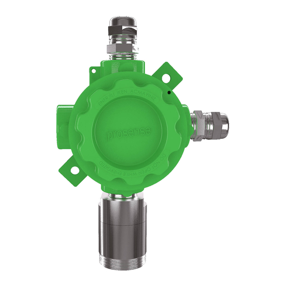
Introduction The Prosense comprises a gas detector body and a choice of sensors heads for detecting flammable gas, toxic gas and oxygen. The construction of Prosense allows it to be used in hazardous area locations; it may also be used in other areas not classified as hazardous. Prosense detectors can be configured with a wide range of different sensors may be used to detect a broader range of target gases. The detector can be configured with optional relay board features three programmable relays for controlling external equipment e.g. alarms, sirens, valves or switches. The detector provides an industry standard 3‐wire, 4‐20mA source or sink output for connection to a dedicated gas detection control system or PLC. Prosense detectors comprises of the main parts as shown below: Cover Locking grub screw Body Mounting plate Sensor head body Sensor holder Field cable entries x2 Sensor head socket Sinter nut Sinter Locking grub screw Sensor head cab Diagram 1: Exploded view 6 PRS‐UM‐P‐EN‐Rev.01‐08.2018 ... -
Page 7: Detector Body
Detector body The detector enclosure has three threaded entries. The two cable entries either side of the upper part of the transmitter housing are for connecting the power source, signal output and relay contacts to associated signalling equipment. The bottom entry allows direct connection of the sensor socket. There is a mounting plate incorporated into the transmitter housing allowing for various mounting configuration options. Diagram 2: Detector body and Sensor Head components 1 : Sensor head body 2 : Sensor holder 3 : Sensor head cap 4 : Sinter nut 5 : Sinter 6 : Junction box – Detector body 7 : Wall mounting adapter 8 : Junction box cover Sensor Head: The Prosense sensor head designed to dedect flammable, toxic gaese and oxygen. They may include NDIR infrared, pellistor or elektrocjemical sensors depending of the target gas and range. 7 PRS‐UM‐P‐EN‐Rev.01‐08.2018 ... -
Page 8: Installation
Installation: Gas detectors should be mounted where a potential hazard of gas is most likely to be present. The following points should be noted when locating gas sensors. When locating detectors consider the possible damage caused by natural events e.g. rain or flooding. Consider ease of access to the gas detector for functional testing and servicing. Consider how escaping gas may behave due to natural or forced air currents. Note: The placement of gas detectors should be determined following the advice of experts having specialist knowledge of gas dispersion, experts having knowledge of the process plant system and equipment involved, safety and engineering personnel. The agreement reached on the location of detectors should be recorded. Each gas has different nature depending on their density. The density of which is lower than air, such as hydrogen, methane or ammonia the sensor head must be located above a possible leak or at the highest points at which major concentrations of gas may be found. The gases and vapours with a density greater than air, the sensor head must be installed beneath a possible leak or at the lowest points at which such gases and vapours may be present. Prosense may provide cable gland together with detector in regards to customer requests. The cable gland provided by Prosense has ATEX certification and provides at least IP65 level protection. The cable glands are only suitable for fixed installations. Cables shall be effectively clamped to prevent pulling or twisting. To provide necessary protection cable glend coupling should be fixed with 20Nm torque when used with three sealings; 18Nm when used with two sealings; 16Nm when used with one sealing. It is the final assamblers/users responsibility to ensure the threaded joint between cable gland and the enclosure meet all the requirements of the applicable standarts for the assembly. Cable gland sealings are suitable for the circular type cables. If other shaped cables will be used the sealings should be replaced with suitable ones. The cable glands provided by Prosense are suitable to use temperature range in which detector works. Prosense may provide plugs and adaptors together with detector in regards to customer requests. The plugs and adaptors provided by Prosense have ATEX certification and provides at least IP65 level protection. These parts should be mounted to detector body in such a way that accidental rotation or loosening will be prevented. It is the final assamblers/users responsibility to ensure the threaded joint between fitting and the enclosure meet all the requirements of the applicable standarts for the assembly. For adaptors and plugs with nominal size of thread equal or lower than 25 mm aliminium alloy shall not be used. Only one adaptors permitted for each cable entry; plugs shall not be used with adaptors. The plugs and adaptors provided by Prosense are suitable to use temperature range in which ... -
Page 9: Mounting The Detector
Mounting the detector: The detector should be mounted vertically as the sensor head pointing downwards. Detector has to be mounted such that the sensor's gas entrance area. The install location should be isolated from vibration, direct sun light and have temperature stability avoided external influences such as splashing water, oil, corrosive aerosols should have at least 30 cm free space beneath the sensor head to provide accessibility for calibration work. should be in air flow between possible leak or collection point and possible source of ignition. Prosense do not recommend to install detectors to : directly above a cooking unit, directly above a sink unit, close to an extractor unit, outdoor without protection against the rain, in places where temperature is outside the admissible operating range, in corrosive environments, inside air vents. in environments where silicon can be found. The Prosense detector has an independent mounting plate consisting of two mounting holes and two holes to attach to detector body. The mounting plate can be adjustable on two diagonal way on to detector body. The detector may be fixed directly to a surface mounting. Follow below steps to mount the detector: 1‐ Decide which diagonal way to use and adjust mounting plate on detector body if ... -
Page 10: Electrical Connections
The mounting plate installed in below position at factory: Diagram 4: Default installaton of mounting plate Electrical connections Caution: All electrical connections should be made in accordance with any relevant local or national legislation, standards or codes of practice. Prosense detectors can operate between 12 ‐ 24 VDC. The connection socket located on main board as given in diagram 8 and details given in below table 2: Output Usage V + Power input (+) 12VDC – 24VDC V ‐ Power input (‐) 12VDC – 24VDC S Current Output Signal (4mA – 20mA) Tablo 1 : Detector output ports and their usage The detector designed to give 4 ‐ 20 mA current output signal. It is also possible to get voltage output via using an additional resistor. Below table 3 gives recommended resistor specifications to get correct voltage output from detector depending of the power source level: Detector Power VDC Resistor Signal level (4mA – 20mA) 12 VDC – 24 VDC 250 Ω, tolerance %1 1 VDC – 5 VDC 12 VDC – 24 VDC 500 Ω, tolerance %1 2 VDC – 10 VDC Table 2 : Detector power and the output resistor Please consider the cable lenght when performing installation in the field. The Prosense detector requires a power supply between 12VDC and 24VDC. Make sure that a minimum 12 VDC supply available at the detector entrance and consider the voltage drop due to cable resistance in case of long distance applications. The maximum loop resistance in the field cable is calculated as follows: R loop = (V controller – V detector min) / I detector ... -
Page 11: Cabling
Example; Diagram 5: Field cabling The controller or power supply is supplying a nominal 24VDC (V controller), the detector minimum allowable voltage is 12VDC (V detector min), therefore the maximum allowable voltage drop between the controller and detector is 12VDC; this means a voltage drop of 6V in each core (V+ core and V‐ core). Minimum power consumption of the detector without any optional module is 1W. The current required to drive the detector at the minimum voltage is (I = P / V) 1.0 / 12 = 85mA (I detector). Maximum power consumption of the detector when optional relay modules installed and all relays are active is 2.5W. The current required to drive the detector at the minimum voltage (I = P / V) 2.5 / 12 = 210mA (I detector). So, the maximum field cable loop resistance (R loop) = 12 / 0.21 = 56 Ohms, or 28 Ohms per core, (allowing for component variations, losses, etc.). The following tables show the maximum cable distances between the controller and transmitter assuming a voltage drop of 6V in each core and for different cable parameters. The tables are examples only and actual cable parameters and source power supply voltage for the application should be used to calculate the maximum cable distance allowed at the installation site. Typical cable data for detector with relay module: Cable size Cable resistance Cable type Maximum Cable length (L) (cross sectional area) Ω/km nearest equivalent Meters 0.5mm2 20AWG 36.8 Ω/km ~500 1.0mm2 17AWG 19.5 Ω/km ~800 1.5mm2 ... -
Page 12: Detector Grounding
Cable and Earth/Ground regimes Effective Earth/Ground bonding is important to ensure good EMC and RFI immunity. The following diagrams show examples of how to earth/ground bond the cable at enclosures. The same principles apply to conduit installations. These bonding techniques provide good RFI/EMC performance. Earth/ground loops must be avoided to prevent the risk of false signal variation. The Earth Screen of the field cable should be “tied to Earth” or connected to Ground at one point only. It is common practise to adopt a STAR EARTH connection regime where all instrumentation Screens are connected at one common point. The Screen at the other end of the cable should be “parked” or terminated into a blank terminal. Diagram 6: Grounding Detector grounding Each detector has grounding screw which utilizes grounding for detector main PCB to detector body. The screw should be located correcty and fixed for all times. In case of any maintenance activity this screw should be checked and fixed to make sure for proper grounding. It is recommended to utilize a No 14 AWG copper, (Stranded or Solid), wire. The following diagrams show where to install the wire into the ground screw of the enclosure. To connect grounding wire, loosen the screw sufficiently; wrap the wire around the screw in a “U” shape; raise the clamp and place the wire between the clamp and ground base; lower the clamp and tighten the screw. Diagram 7: Detector grounding screw 12 PRS‐UM‐P‐EN‐Rev.01‐08.2018 ... -
Page 13: Default Configuration
Default configuration Prosense detectors preconfigured to provide signal from analog output depending on the detector and gas type: Function Value/Setting Meaning 2.0 mA Fault 2.0 mA Warmup Signal output 3.0 mA Calibration 4.0 mA to 20.0 mA Normal gas measurement 22.0 mA Maximum over range Value is gas dependant Lower alarm level Alarm Relay 1* De‐energized Energizes on alarm Contact Normally Open (NO) Closes on alarm Value is gas dependant Higher alarm level Alarm Relay 2* De‐energized Energizes on alarm Contact Normally Open (NO) Closes on alarm 2.0mA Detector Fault Fault Relay * Energized De‐Energizes on alarm Contact Normally Open (NO) Closes on alarm (*) Relays are only available with optional relay module ... -
Page 14: Detector Configuration
Detector has integrated RS485 Serial communication devices. Hence both digital and analog outputs are available onboard. Port definitions are given in table6: Port Usage V + Power input (+) 12VDC – 24VDC V ‐ Power input (‐) 12VDC – 24VDC S Current Output Signal (4mA – 20mA) A RS485 Serial communication output port A B RS485 Serial communication output port B Table 5 : Detector output ports and their usage Detector Configuration The Prosense dedecor has three different types of connection depending on installed boards: 1. Single 4‐20mA output (default option) 2. RS485 Modbus serial communication output 3. 3‐Relay outputs 4-20 mA output: The default configuration provides single 4‐20mA signal output. Prosense detectors can be connected to control panels on the market having 4‐20mA input signal. Signal wiring from detector and the control panel should be carried out by shielded cables. Wires cross section depends on the distance between the control panel and the detector. The details given in power cabling are valid as well for signal output. We recommend to use values given in table 4 (see page 13) as cabling best practices. Please avoid any interruption in case any junctions on wires. The shield is to be grounded from the control panel side only and never connect the shield to the detector. Please make sure clutching or crimping aparats are not loosen or oxidized. If the analog output shortcut due to an error the output will be dropped to 2mA as detector has a self defending mechanism implemented. Analog output will be automatically ... - Page 15 meters. The wiring for detectors utilized with RS485 board should be done by using connection cable EIA RS485 2 core wires with section 0.22 / 0.35 mm2 and shielded. Nominal capacity between the wires < 50pF/m and nominal impedance 120 Ohms. Detectors will be wired in daisy chain (bus) mode. We recommend not to use star mode connection due to negative impact of interference. Each detector should have unique address number in the chain. The detectors would not be recognised by control panel if same address given to them. Detectors can have addresses between 1 to 63. Address zero(0) is reserved. The address of detector can be adjusted via using DIP‐Switch set on the board: 1 2 3 4 5 1 Diagram 9: RS485 Modbus serial communication address and switch position The last detector in the chain should have 120 Ohms RS485 termination resistor. The resistor is already implemented on the board by default but not activated. User should activate the termination resistor via using the termination pin once the installation completed: RS485 termination pins Diagram 10: RS485 Modbus serial communication module end of line jumper 15 PRS‐UM‐P‐EN‐Rev.01‐08.2018 ...
-
Page 16: Detector Relay Module
The power connection we recommend to use seperate 2 wire cable with specification given earlier in this document (see Electrical Connections section at page11). Once the cabling is completed please check each detector has at least 12 VDC power. Detector Relay module: Prosense provides optional relay modules for Prosense detectors. The relay module details are given below: Relay out adjutment pins NO / NC Alarm1, Alarm2 and Fault LEDs Power LED Alarm2 Relay output pins Alarm1 Relay output pins Main board connection Fault Relay output pins SW1 and SW2 Alarm level adjustment pins Diagram 11: Relay module The relay board has 3 relay outputs: Port Usage Fault Fault Relay output Al1 Alarm 1 Relay output Al2 Alarm 2 Relay output Table 6 : Relay module output ports and their usage 16 PRS‐UM‐P‐EN‐Rev.01‐08.2018 ... - Page 17 All output pins located on Prosense IR detector can be used simultanously. That means user can use all relay outputs, analog (4‐20mA) output and RS485 digital output at same time if implementation equipment allows their usage. Each relay has 3 pins to adjust how to behave in case of alarm which are NO : Normally Open NC : Normally Close The relay output pin positions shown below: Normally Open (NO) Normally Close (NC) Table 7 : Relay output pin positions The Fault relay is set to NO (Normally Open – Energised) and energised. Hence fault relay LED is always active. It does not mean that there is a fault on detector. If the power LED is active and fault LED is off it means that there is a fault condition on the detector. The fault relay will be de‐energized in case of power failure. The alarm relays set to NO (Normally Open – De‐Energised) position at factory. The alarm levels are also adjustable via using SW1 and SW2 alarm level pins. Alarm levels are defined as percentage in LEL for flammable gases. The alarm levels can be adjusted using jumpers to switch SW1 and SW2. Possible options are given in table 9: SW1 SW2 Al1 Level Al2 Level Open Open 10 LEL 15 LEL Open Closed 10 LEL 20 LEL Closed Closed 20 LEL 25 LEL ...
-
Page 18: System Status
Open Open 19 %vol 23 %vol Open Closed 19 %vol 22 %vol Closed Closed 18 %vol 22 %vol Closed Open 18 %vol 23 %vol Table 11: Alarm level (% Vol) pin positions for Oxygen detectors System Status The Prosense IR detectors has one LED on main board to show actual status of the detector. In normal conditions whiel detector works properly the LED blinks with 1 second period (one blink in a second). If detecor is in fault condition LED illuminates with 250 ms period (four blinks in a second) and the detector analog output gives 2mA on S port. If detector could not get enough power (lower than 12 VDC) it will also raise fault status. First time switch on (Commissioning) WARNING The following procedure requires the detector Cover to be removed while carrying out supply voltage checks. Therefore the appropriate permits to work should be sought in preparation. Prior to carrying out any HOT WORK ensure local and site procedures are followed. Ensure that the associated control panel output actuation is inhibited so as to prevent false alarms. Caution: The following procedure should be followed carefully and only performed by suitably trained personnel ... -
Page 19: Calibration
Calibration It is recommended to periodically carry out calibration to ensure correct operation. Calibration should be done by a person who trained and certified by local or international authorities. Prosense detector calibration includes two steps which are zero and span calibration. During the calibration both steps have to be completed. Otherwise the calibration would not be saved and values invalidated by detector internal control mechanism. Detector should be powered and stabilized for at least 30 minutes before calibration. Zero calibration should be done by clean air or N2 gas depending of the detector and sensor type. Span calibration should be done by specific gas combinations and levels depending of the detector and sensor type. Please contact Prosense to get zero and span calibration gas details. To calibrate the detector, use an appropriate span gas cylinder, constant flow regulator and Prosense Gas Cap. The flow rates used for calibration gas are as follows: Gas Flow rate(L / Min) Clean air or N2 for zeroing 0.5 to 1.0 Falmmable (Catalytic) 0.5 to 1.0 O2 0.5 to 1.0 H2S 0.5 to 1.0 CO 0.5 to 1.0 H2 0.5 to 1.0 Flammable (IR) 0.4 to 0.6 CO2 IR 0.4 to 0.6 Table 9: Gas flow rates for calibration Calibration procedure may vary depending on the Prosense detector model. If Prosense Gas Monitor software available for calibration, first enable communication between detector and computer via setting the first address switch to ON position. Then give clean air (N2 for IR sensors) gas to sensor head to perform zero. It would be better to follow the ADC value in graph to see and make sure sensor has been stabilized. Then press “Set Zero” button to start ... -
Page 20: Maintenance
If Prosense Gas monitor software is not available follow below procedure step by step. Otherwise the calibration would not be completed and non of the values recorded. 1‐ Put detector in calibration mode. To enable calibration mode the last switch on address switch board should set to ON. If it was OFF it should need to set to ON. If it was already ON it should need to set first OFF, then 10 seconds later set to ON. 2‐ Apply zero gas (clean air or N2 depending of the detector and sensor type) to the sensor for zeroing. The LED on main board will solid for 75 seconds and than it will return to normal speed (1 second period). Once LED returned to normal flashing speed zeroing is completed. 3‐ Apply span gas and wait 75 seconds. 4‐ Set last switch to OFF position to start span calibration. 5‐ Detector will set span level automatically. The LED on main board will solid for 75 seconds and than it will return to normal speed (1 second period). Once LED returned to normal flashing speed span calibration is completed. It is not possible to perform only zero or only span calibration. It should be done in given order. Analog output will set to 3mA level during calibration steps performed, alarms and fault status or relays will be deactivated. If you wan to monitor analog output via using a multimeter you must use a resistor while serially connecting the multimeter. Otherwise detector will think someone has did short circuit on analog output hence it will enable saving mode and set output level to 2mA. Maintenance Proactive maintenance: All gas detectors including both for flammable and toxic gases should have to pass a functional test and calibration every three to six months according to EN 60079‐17 industiral standarts. The test results and calibration reports should be recorded in maintenance books. Operational Life: Flammable gas sensor made by using the pellistors that suffer from a loss of sensitivity when in the presence of poisons or inhibitors, e.g. silicones, sulphides, chlorine, lead or halogenated hydrocarbons. The pellistors are poison resistant to maximize the operational life of the Catalytic flammable sensor. A typical operating life, subject to the presence of poisons/inhibitors is 36 months. ... -
Page 21: Servicing
Sensor replacement: The Flammable NDIR cells that are used with the Prosense IR Sensor Head have no serviceable parts. When they have reached the end of their operational life, simply replace the cell. Sinter replacement: Due to environmental conditions the metal filter ‐ sinter at sensor head might lost permeability that could negative impact on sensor performance. For example if the installation includes cement or similar dust the sinter would be block the air/gas entry to sensor. The sinter should be checked visually and replaced if necessary. To replace sinter please check diagram‐1 and follow the below procedure: 1‐ Power of the Prosense detector 2‐ Loosen the locking grub screw 3‐ Unscrew the sensor head cap that holds the dirty sinter 4‐ Screw the sensor head cap including the clean sinter 5‐ Fix the Locking grub screw Sensor head replacement: Prosense senser head is a seperate part that can be replaced in the field. The sensor head includes integrated sensor, electronic device and sinter in it. To replace sensor head: 1‐ Power‐Off the Prosense detector 2‐ Disconnect sensor cables from the detector main board 3‐ Remove the sensor head from the body 4‐ Install sensor head 5‐ Connect the sensor cables to detector main board ... -
Page 22: General Specification
General specification Use: 3‐wire, 4‐20mA analog and 2 wire RS485 digital gas detector transmitter for use with directly installed flammable gas sensors. For the protection of personnel and plant from flammable gas hazards. Electrical Specifications: Input Voltage Range 12 to 24VDC (24VDC nominal) Max Power Consumption Max 2.5 Watts. at 24VDC Current output 4‐20mA 2.0 mA Fault 4.0 mA to 20.0 mA Normal gas measurement 2.0 mA Inhibit (during configuration/warming) 3.0 mA Calibration 22.0 mA Maximum over range 3 x screw terminals suitable for wire diameter 0.5mm2 to 2.5mm2 (20AWG to 13AWG) for power input and analog(4‐20mA) output, 2 x screw terminals suitable for wire diameter 0.5mm2 to 2.5mm2 Terminals (20AWG to 13AWG) for RS485 digital output 3 x (1A 30VDC, 0.5A 125VAC, 0.3A 80VDC). Selectable normally open or normally closed (switch). Alarm relays de‐energised and fault relay Relays energised. Communication RS485, Modbus RTU Table 10: Electrical specifications Detector Body Specifications: Material Epoxy painted aluminium alloy Weight Aluminium Alloy :1.33kg (with Sensor Header) Mounting ... -
Page 23: Warranty Statement
Warranty statement All products are designed and manufactured to the latest internationally recognized standards by Prosense Technology under a Quality Management system that is certified to ISO 9001. As such Prosense Technology warrants its products against defective parts and workmanship and will repair or (at its option) replace any instruments which are or may become defective under proper use within 12 months from date of commissioning by an approved Prosense Technology representative or 18 months from date of shipment from Prosense Technology, whichever is the sooner. This warranty does not cover disposable batteries or damage caused by accident, abuse, abnormal operating conditions or poisoning of sensor. Defective goods must be returned to Prosense Technology premises accompanied by a detailed description of any issue. Where return of goods is not practicable Prosense Technology reserves the right to charge for any site attendance where any fault is not found with he the equipment. Prosense Technology shall not be liable for any loss or damage whatsoever or howsoever occasioned which may be a direct or indirect result of the use or operation of the Contract Goods by the Buyer or any Party. This warranty covers instrument and parts sold to the Buyer only by authorized distributors, dealers and representatives as appointed by Prosense Technology. The warranties set out in this clause are not pro rata, i.e. the initial warranty period is not extended by virtue of any works carried out there under. In no event will Prosense Technology be liable for any incidental damages, consequential damages, special damages, punitive damages, statutory damages, indirect damages, loss of profits, loss of revenues, or loss of use, even if informed of the possibility of such damages. Prosense Technology's liability for any claims arising out of or related to this product will in no case exceed the order value. To the extent permitted by applicable law, these limitations and exclusions will apply regardless of whether liability arises from breach of contract, warranty, tort (including but not limited to negligence), by operation of law, or otherwise. 23 PRS‐UM‐P‐EN‐Rev.01‐08.2018 ...
Need help?
Do you have a question about the P Series and is the answer not in the manual?
Questions and answers