
Summary of Contents for Curtiss-Wright DTS1
- Page 1 DTS1 CSfC / ECC Cryptographic Data Transport System User Guide Part Number: DDOC0099-000-AH...
- Page 2 This Page Intentionally Left Blank...
- Page 3 DDOC0099-000 6/29/20 Add Quick Start section. All other corrections / updates 0620-0012 noted by change bars. The Curtiss-Wright DTS1 CSfC User Guide (DDOC0099-000) is made up of the following individual chapters and appendices. Chapter / Appendix Topic Content Revision Introduction...
- Page 4 NOTES are used to supply amplifying information that will result in ease of testing or be beneficial to personnel. This information typically precedes procedural steps. It also may be present in narrative text as well. DTS1 CSfC Front Matter © 2020 Curtiss-Wright Defense Solutions...
- Page 5 Pressing more than one key in sequence. xx,yy Variable in error messages and text. jobfile.dat File names. This style Refers to Denotes the result of an action or procedure. Hyperlink. Controls on equipment. STOP DTS1 CSfC Front Matter © 2020 Curtiss-Wright Defense Solutions...
- Page 6 Installation 4.1 Package..............................4-1 4.2 Inspection ..............................4-1 4.3 Mounting..............................4-2 4.4 Cables ............................... 4-3 4.4.1 Power Cable ............................ 4-3 4.4.2 Utility Cable ............................. 4-4 4.4.3 Ethernet Cable ..........................4-4 4.4.4 Ground Cable ..........................4-5 DTS1 CSfC Table of Contents...
- Page 7 5.5 Zeroize HWE Key / Delete SWE Container / RMC Purge ............... 5-15 5.5.1 Zeroize HWE Key .......................... 5-15 5.5.2 Delete SWE Container ........................5-15 5.5.3 RMC Purge ........................... 5-15 Quick Start 6.1 Connections / Preparation ......................... 6-1 6.2 Initialization..............................6-1 6.3 Login................................6-3 DTS1 CSfC Table of Contents...
- Page 8 8.1.1 Initialize / Log In ..........................8-1 8.1.2 Key Load / Unload ........................... 8-1 8.1.3 Key Removal / Zeroize ........................8-1 8.1.4 Key Commands ..........................8-1 8.2 DTS1 ................................. 8-1 8.2.1 Versions ............................8-2 8.2.2 Configure ............................8-2 8.3 RMC Module.............................. 8-2 8.3.1 RMCCTL Definitions ........................
- Page 9 11.1 RMC Module............................11-1 11.1.1 Install ............................11-1 11.1.2 Remove ............................11-2 11.2 Battery ..............................11-2 Command Line Interface 12.1 DTS1 ..............................12-1 12.2 RMC Module............................12-1 12.3 Commands ............................12-1 12.3.1 amnt ............................12-2 12.3.2 cmfwupdate ..........................12-4 12.3.3 cmkey ............................12-5 12.3.4 cmlogin ............................
- Page 10 B.1 Power Connector J1 / Power Lab Cable ....................B-1 B.2 Utility Connector J2 / Utility Lab Cable......................B-2 B.3 Ethernet Connector J3 / Ethernet Lab Cable ....................B-3 B.4 Ground Lug ...............................B-5 Ordering Information C.1 DTS1 / RMC Module / Lab Cables......................C-1 DTS1 CSfC viii Table of Contents...
- Page 11 Figure 2.2 DTS1 Chassis / Components ......................2 - 2 Figure 2.3 DTS1 Rear Panel / Battery Access Cover and Rear Connectors............ 2 - 3 Figure 2.4 DTS1 Processor Carrier PCB Programming Connector / Write-Enable Switch ......2 - 3 Figure 2.5...
- Page 12 RMC Module LED Fault Indications ...................... 9-2 Table 9.3 Encryptor Error Codes........................... 9-2 Table A.1 DTS1 / RMC Calculated Mean Time Between Failures ................ A-4 Table B.1 Power Connector J1 Signals ......................... B-1 Table B.2 Power Lab Cable (VS-DTS1PWRCAB-0) ..................... B-1 Table B.3...
- Page 13 The unit requires the use of a Removable Memory Cartridge (RMC) module. From this point forward, the product will be referred to as the DTS1 and the associated cartridge will be referred to as the RMC module.
- Page 14 DTN_support@curtisswright.com • Fax: (937) 252-1465 • World Wide Web address: www.cwcdefense.com Ordering Process To learn more about Curtiss-Wright Defense Solutions' products or to place an order, please use the following contact information. • E-mail: DTN_info@curtisswright.com • World Wide Web address: http://www.cwcdefense.com/...
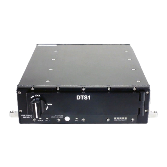
- Page 15 The Curtiss-Wright DTS1 (Figure 2.1) is a rugged Network Attached Storage (NAS) device with solid state storage capacities from 128 GB up to 4 TB. The DTS1 provides data storage to assorted network clients via two IEEE 802.3 / 802.3u / 802.3ab Ethernet ports. The DTS1 is a ruggedized unit designed to operate on vehicles, in field stations, or in laboratories.
- Page 16 Connector J1 is used to connect the DTS1 to 28 VDC (operating voltage). In addition, the DTS1 has a removable panel located on the underside of the unit. It is removed to allow replacement of the crypto module battery.
- Page 17 2.1.2 RMC Module One RMC module (Figure 2.5) is housed in the DTS1. The RMC module is accessed via a sealed door with a quarter-turn latch located on the front panel of the unit. The RMC module within the DTS1 is also a rugged compact unit that can be personally transported with minimal precautions to a secure location or deployment.
- Page 18 The second security layer is software data encryption. Both encryption processes are performed in the DTS1, one in the HW crypto module, the other by the Processor. The hardware encryption key is retained in the DTS1 crypto module memory, the software encryption key is stored on the RMC module.
- Page 19 The CLI then sends this data as a user-generated HMAC to the DTS1 HWE layer. The layer compares the user HMAC and the HWE layer HMAC. If they are the same, the user is logged in. If they do not compare, the user is denied access.
- Page 20 Subsequent use of the RMC module is dependent upon the proper encryption key / passphrase being entered using the CL). Failure to enter the proper information will result in the RMC module being inaccessible for data storage or use. 2.3.3 Zeroize There are two methods to zeroize the DTS1: • Local • Remote To locally initiate zeroization, the KEY CLEAR button is depressed and held for a minimum of five seconds.
- Page 21 Supported packet capture protocol • PCAP • Supported video stream capture protocol • • Client remote boot from DTS1 via Preboot eXecution Environment (PXE) • User control, status, & maintenance interface • Command Line Interface (CLI) via: • Secure shell (SSH) •...
- Page 22 STATUS (green): on when RMC module is installed, mounted and ready for access • ACTIVITY (green): on when disk is accessed (not supported on some RMC module configurations) • FAULT (red): DTS1 system monitor has detected a fault with the RMC module DTS1 CSfC 2 - 8 Overview Revision 5.0...
- Page 23 User Guide DDOC0099-000-AH Controls and Indicators Chassis Indicators The DTS1 has four LED status indicators (Figure 3.1) on the bottom of the front panel: • POWER • FAULT • KEY LOADED • DRIVE CAPACITY The brightness of the chassis LEDs can be independently set from 0 to 100% brightness. This accomplished by changing the duty cycle of the power applied to the individual LEDs.
- Page 24 When this button is pushed and held for a minimum of 5 seconds, all encryption related material within the DTS1 will be erased. This includes loaded keys, stored keys, and all previously loaded login/authentication credentials (user names and passwords). After zeroization, the yellow KEY LOADED LED will turn off.
- Page 25 RMC module is ready for removal, the STATUS LED will blink one time every five seconds. Removal may also be requested with the CLI command rmcctl. DTS1 CSfC 3 - 3 Controls and Indicators Revision 2.0 © 2020 Curtiss-Wright Defense Solutions...
- Page 26 Ethernet Lab Cable Inspection The DTS1 is a two-part data storage system that consists of a DTS1 chassis and a RMC module. Additional accessories may be included (if ordered). All received items should be inspected for damage. Inspect all units as follows: •...
- Page 27 Dzus mount. If installation and removal of the RMC module is desired while the DTS1 remains mounted, be sure to allow clearance (Figure 4.4) for the door to open and the RMC to be positioned in front of the DTS1. DTS1 Standard Mount...
- Page 28 0.994 (25.24) 4.00 (101.6) DDOC0099-0007 Figure 4.4 DTS1 Required Door Clearance Cables All connections to the DTS1 are on the rear panel (Figure 4.5). Be sure the power supply is off when making connections. RS-232 Ethernet Ethernet Power Ground DDOC0099-0009 Figure 4.5...
- Page 29 Utility Lab Cable 4.4.3 Ethernet Cable The Ethernet Lab Cable (VS-DTS1ETHCAB-J3) (Figure 4.8) is used to make network connections to the DTS1. Refer to paragraph B.3 Ethernet Connector J3 / Ethernet Lab Cable for connector pin signal information. Connections •...
- Page 30 Ground Cable A ground cable is required, but not provided. The ground cable (DTS1 Ground Connection) terminal is installed on the DTS1 ground stud E1. The provided nut should be torqued to 18 in. lb. to ensure proper connection. Torque Nut to 18 in. lb.
- Page 31 The software layer password /passphrase can be incorrectly entered four times without issue. On the fifth try if an incorrect password / passphrase is entered, the DTS1 will automatically reboot. There is no limitation to the number of times an incorrect entry /reboot occurs.
- Page 32 User Guide DDOC0099-000-AH Check Hardware Layer Status NOTE All values listed below should equal na or 0 for a new DTS1 / RMC module. 1. Check login status Command: cmlogin • init =0 not initialized / =1 initialized • login =0 not logged into / =1 active login Example: cw_dts>...
- Page 33 MAC........... Message Authentication Code is a value used to validate messages carrying a key. CM ..........Crypto Module is the circuitry in the DTS1 that manages encryption keys and uses them to encrypt/decrypt data. Install ......... Sending the key from the user’s workstation to the encryption chip serving a specified RMC module slot.
- Page 34 NTER Example cw_dts> cmkey -s 0 -d -p --force [cmkey] Please enter plaintext DEK: [User-generated plain text DEK string] Please enter current PSK: [Curtiss-Wright provided PSK string] CMKEY: action=inst slot=0 status=ok [!cmlogin] OK DTS1 CSfC 5 - 4 Encryption Revision 6.0...
- Page 35 / explained in paragraph 5.3.4.3 Status Report. 5.3.4.1 Pain Text DEK Type cmkey --save [0 thru 31] -d [User-generated plain text DEK string] - p [Curtiss-Wright provided PSK string] and press E key. NTER Example (DEK / PSK) cw_dts>...
- Page 36 5.3.4.3 Status Report NOTE The DTS1 has only one RMC module available (s0), s1 and s2 will always be unavailable (=0). The cmkey command without options reports key status. To obtain the key status type cmkey and press E key.
- Page 37 RMC modules from the field into a lab DTS1. In both cases the keys must be stored or restored in the DTS1 crypto module. To autoload a key type cmkey --auto –s 0 and press E key.
- Page 38 The RMC module must have services assigned before the software encryption layer can be initial- ized / entered. The rmcctl -C command allows the user to view and alter the DTS1 disk encryption options. The software encryption layer uses containers to hold the data. Creation of a container requires the use of a password or passphrase.
- Page 39 1. Type rmcctl -E and press E key. NTER NOTE After five failed attempts to open the SWE container, the DTS1 will reboot and another five attempts be granted. 2. Enter the password / passphrase and press E key. NTER ...
- Page 40 Example of RMC Module Status cw_dts> rmcctl [rmcctl] RMC_S#: hcryp osdr size serv scryp osdm mntpoint ********************************************************************************* rmc0p1 RMC_S0: 50 GB rmc0p2 RMC_S0: 50 GB [!rmcctl] OK DTS1 CSfC 5 - 10 Encryption Revision 6.0 © 2020 Curtiss-Wright Defense Solutions...
- Page 41 Example of RMC Module Status cw_dts> rmcctl [rmcctl] RMC_S#: hcryp osdr size serv scryp osdm mntpoint ********************************************************************************* rmc0p1 RMC_S0: 50 GB rmc0p2 RMC_S0: 50 GB [!rmcctl] OK DTS1 CSfC 5 - 11 Encryption Revision 6.0 © 2020 Curtiss-Wright Defense Solutions...
- Page 42 3. Partition 2: Enter the password / passphrase and press E key. NTER If the passphrase is entered correctly the following message will be displayed: RMC_C0; action=enter status=OK ‘Resetting attempts to 0”. DTS1 CSfC 5 - 12 Encryption Revision 6.0 © 2020 Curtiss-Wright Defense Solutions...
- Page 43 ********************************************************************************* rmc0p1 RMC_S0: 100GB ext4 rmc0p2 RMC_S0: 25 GB ext4 [!rmcctl] OK • To format and mount the SWE containers: Command: rmcctl -p all -F -M DTS1 CSfC 5 - 13 Encryption Revision 6.0 © 2020 Curtiss-Wright Defense Solutions...
- Page 44 -p 2 -D Example of RMC Module Status cw_dts> rmcctl [rmcctl] RMC_S#: hcryp osdr size serv scryp osdm mntpoint ********************************************************************************* rmc0p1 RMC_S0: 100GB rmc0p2 RMC_S0: 25 GB [!rmcctl] OK DTS1 CSfC 5 - 14 Encryption Revision 6.0 © 2020 Curtiss-Wright Defense Solutions...
- Page 45 Zeroization affects only the crypto module HWE key. It does not affect the RMC module. The data on the RMC module is still accessible: • If the RMC module can be placed in another DTS1 with the same DEK / EDEK loaded in its crypto module. •...
- Page 46 2. Purge all RMC modules with enhanced overwrite. Command: rmcpurge -s all -E Example: Enhanced erase of all RMC modules cw_dts> rmcpurge -s all -E [rmcpurge] RMC_P0: status=OK RMC_P1: status=OK RMC_P2: status=OK [!rmcpurge] OK DTS1 CSfC 5 - 16 Encryption Revision 6.0 © 2020 Curtiss-Wright Defense Solutions...
- Page 47 Make sure no power is applied to DTS1 when inserting / removing RMC. NOTE At a minimum, the DTS1 CSfC must have an RMC installed and be connected to both a computer and 28 VDC power source. 1. Turn door latch CCW, open door, and insert RMC into DTS1.
- Page 48 Initialization Quick Start Process Flow NOTE The PSK is provided on a removable label placed on top of DTS1 when shipped. 2. Using a 3rd-party application and factory supplied PSK, decrypt user token obtained in step 1. Save resulting decrypted user token for future use / logins.
- Page 49 NONE ---- [!rmcctl] OK NOTE DTS1 CSfC units require use of software encryption in addition to hardware encryption. NOTE Disks cannot be partitioned after software encryption has been performed. NOTE The RMC module must have services assigned before software encryption layer can be initialized.
- Page 50 ---- [!rmcctl] OK 7. Open software encryption container: rmcctl -E 8. When prompted, enter same password / passphrase as previously entered. 9. View RMC status: rmcctl DTS1 is ready to use with CSfC encryption. cw_dts> rmcctl [rmcctl] RMC_S#: hcryp...
- Page 51 Setup / Connections NOTE The DTS1 is powered by a user-supplied 28 VDC power supply and does not have a power switch of its own. The DTS1 is powered up by turning on the 28 VDC supply. 1. If not previously accomplished, connect cables to DTS1 connectors (Figure 7.1).
- Page 52 Serial port access is recommended for initial configuration of the DTS1. This topic describes how to use the DTS1 Command Line Interface (CLI) to configure the DTS1. Refer to Command Line Interface section for more information on the commands used in this topic.
- Page 53 Host Name (or IP Address): see Table 7.1 4. Click Open button. A terminal screen should activate. 5. Click Enter button. A login prompt should activate. DTS1 CSfC 7 - 3 Operation Revision 4.0 © 2020 Curtiss-Wright Defense Solutions...
- Page 54 -e eth0 -i [desired IP address] -n [desired netmask] NOTE The DTS1 can be configured as a DHCP client if desired. When configured in this manner, the IP address is set remotely by a DHCP server. 4. Configure the DTS1 as a DHCP client as follows: a.
- Page 55 Example cw_dts> sysdate -d yyyy/mm/dd -t hh:mm:ss Login Logging into the DTS1 is a three-part process. Before the RMC module can be accessed or configured, the user must (in the following order): 1. Log into DTS1. 2. Initialize HWE layer.
- Page 56 Storage Media NOTE The DTS1 must have the hardware encryption layer initialized and open before the RMC module (storage media) can be accessed. If desired, the RMC module disk can be used without partitioning. The unpartitioned disk must have services started and assigned before formatting and mounting.
- Page 57 Create 4 partitions on a 100GB RMC module as follows: 10GB, 50GB, 20GB, 20GB. NOTE Partition must be 100MB or greater. Command: rmcctl -P 4 10GB 50GB 20GB 20GB DTS1 CSfC 7 - 7 Operation Revision 4.0 © 2020 Curtiss-Wright Defense Solutions...
- Page 58 [rmcctl] RMC_S#: hcryp osdr size serv scryp osdm mntpoint ********************************************************************************* RMC_S0: 33 GB rmc0p1 RMC_S0: 33 GB rmc0p2 RMC_S0: 33 GB NONE ---- [!rmcctl] OK DTS1 CSfC 7 - 8 Operation Revision 4.0 © 2020 Curtiss-Wright Defense Solutions...
- Page 59 BOOTCFG tel=0 snmp=0 status=ok http=1 dhcp=0 tftp=0 LIVECGFG cifs=1 nfs=1 ftp=1 tel=0 snmp=0 status=ok [!rmcctl] OK Restart all services. Command: serv -a 1 DTS1 CSfC 7 - 9 Operation Revision 4.0 © 2020 Curtiss-Wright Defense Solutions...
- Page 60 Add a mount point name to partitions 1 and 2 of a100 GB RMC module with two partitions. NOTE Must be done as two separate commands. Command: rmcctl -p 1--mntpoint [name 1] rmcctl -p 2--mntpoint [name 2] DTS1 CSfC 7 - 10 Operation Revision 4.0 © 2020 Curtiss-Wright Defense Solutions...
- Page 61 Example of RMC Module Status cw_dts> rmcctl [rmcctl] RMC_S#: hcryp osdr size serv scryp osdm mntpoint ********************************************************************************* ext4 rmc0p1 RMC_S0: 50 GB rmc0p2 RMC_S0: 50 GB NTFS [!rmcctl] OK DTS1 CSfC 7 - 11 Operation Revision 4.0 © 2020 Curtiss-Wright Defense Solutions...
- Page 62 Format / Mount NOTE NTFS format is not supported on an unpartitioned RMC module. Format (ext4) / mount an unpartitioned 100GB RMC module. Command: rmcctl -F -M DTS1 CSfC 7 - 12 Operation Revision 4.0 © 2020 Curtiss-Wright Defense Solutions...
- Page 63 Add the force option (---force) if changing format from NTFS to ext4. Format (ext4) / mount partitions 1 through 4 of a 100GB RMC module. Command: rmcctl -p all -F -M DTS1 CSfC 7 - 13 Operation Revision 4.0 © 2020 Curtiss-Wright Defense Solutions...
- Page 64 The DTS1 supports use of Internet Small Computer System Interface (iSCSI). It is configured to use either Ethernet port 0 or port 1. The desired Ethernet port must have an active link before running istarget.
- Page 65 PCAP operation as well. The DTS1 supports use of the PCAP command to capture packets traveling over a network. Two data streams may be captured at any one time (Ethernet ports 0 and 1). A unique file name must be used with each recording in order to retain all recordings.
- Page 66 [!pcap] OK Health The DTS1 has internal sensors that monitor critical environmental and operational parameters. The software provides this information to the user via the CLI when commanded. A FAIL status will be posted for any values that are out of tolerance.
- Page 67 7.8.1 IBIT (Initiated BIT) NOTE Results will be provided as 1 (Pass), 0 (Fail), and NA (function not active) The ibit command provides a snap-shot of the DTS1 status. To view status, type ibit and press key. NTER • IBIT_MON line provides results for system monitor subsystem.
- Page 68 The tarball will have to uncompressed and the digital signature verified before loading the files into the DTS1 flash memory. The fupdate command boots the DTS1 system into a RAM disk image where the user can install a new disk image onto the system. Upon logging into the new RAM disk image, a menu of operations to restore and verify the restoration of a new disk image activates.
- Page 69 Access from Windows as NAS Device NOTE When the partitions are formatted and mounted, they can be accessed from a PC running Windows. 1. Log into the DTS1 via SSH. Refer to paragraph 7.2.1.2 Ethernet. 2. Type rmcctl and press E key. NTER ...
- Page 70 NOTE When the partitions are formatted and mounted, they can be accessed from a PC running Linux. NOTE This procedure is performed via Ethernet connected to DTS1 port 0. 1. Open a terminal window 2. Type ssh admin@192.168.1.1. 3. Press E key.
- Page 71 User Guide DDOC0099-000-AH System Configuration The commands below are used to configure the crypto module, DTS1, and associated RMC module. Crypto Module The cmlogin command allows for initialization of / logging into the Hardware Encryption (HWE) crypto module. For status information, issue cmlogin without options. Refer to paragraph 12.3.4 cmlogin for detailed information about initializing /logging into the HWE crypto module.
- Page 72 RMC Module NOTE The DTS1 has only 1 RMC module slot. As a result, the -s option is always -s 0. Refer to paragraph 12.3.21 rmcctl and paragraph 12.3.27 serv for detailed information about configuring the RMC module.
- Page 73 -d ........DHCP Service. serv -f ........FTP Service. serv -n ........NFS Service. serv -s ........SNMP Service. serv -t ........TFTP Service. serv -z ........Telnet Service. serv -w........HTTP Read Service. DTS1 CSfC 8 - 3 System Configuration Revision 1.0 © 2020 Curtiss-Wright Defense Solutions...
- Page 74 The chart below provides a basic failure analysis by observing status indicators. If any one of the LEDs exhibits the failure status, the DTS1 may not function properly. The investigative/remedial actions offered should only be tried one or two times. Refer to paragraph 3.1 Chassis Indicators for information regarding front panel LEDs.
- Page 75 Encryptor battery dead. Replace battery. Refer to paragraph 11.2 Battery for detailed instructions. Encryptor Error Codes NOTE If problems persist, contact Curtiss-Wright Defense Solutions Customer Support. Refer to paragraph 1.5 Technical Support for contact information. Refer to Table 9.3 for fault information.RMC module Table 9.3...
- Page 76 Memory allocation error 0x0E04 E2PROM Write error 0x0E05 E2PROM Read error 0x0F03 STORAGE Memory allocation error 0x0F04 STORAGE Write error 0x0F05 STORAGE Read error 0x2002 PBKDF2 Invalid input length DTS1 CSfC 9 - 3 Troubleshooting Revision 0.0 © 2020 Curtiss-Wright Defense Solutions...
- Page 77 10.1 SNMP MIB The DTS1 supports Simple Network Management Protocol (SNMP). The user may configure SNMP for a Windows workstation via the Windows Control Panel. The user should consult with their network administrator for details on configuration and utilization of the SNMP traps and other data capture programs.
- Page 78 SYNTAX OCTET STRING (SIZE(1..8192)) MAX-ACCESS read-only STATUS current DESCRIPTION "Output of command: ledctrl" ::= { dtsSnmpValues 7 } dtsSENS OBJECT-TYPE SYNTAX OCTET STRING (SIZE(1..8192)) DTS1 CSfC 10 - 2 Simple Network Management Protocol Revision 1.0 © 2020 Curtiss-Wright Defense Solutions...
- Page 79 ::= { dtsSnmpValues 11 } dtsCMKEY OBJECT-TYPE SYNTAX OCTET STRING (SIZE(1..8192)) MAX-ACCESS read-only STATUS current DESCRIPTION "Output of command: cmkey" ::= { dtsSnmpValues 12 } DTS1 CSfC 10 - 3 Simple Network Management Protocol Revision 1.0 © 2020 Curtiss-Wright Defense Solutions...
- Page 80 If the problem persists, contact Curtiss-Wright Defense Solutions. NOTE Power must be applied to DTS1 for RMC module STATUS LED to turn ON. 7. Open the DTS1 door and observe the RMC module STATUS LED. When green LED turns ON, RMC module is ready. Slide...
- Page 81 "-R" option instead of using the Removal button. 1. Rotate the door latch a quarter turn and open the door. 2. If the DTS1 is off, grasp the RMC module handle (Figure 11.2) and pull the unit straight out. NOTE Use rmcctl -r to initiate the removal process via the CLI.
- Page 82 (see Detail A) Connector Pins Battery Access Panel Battery DETAIL A DDOC0099-0026 Figure 11.3 Battery Assembly Replacement DDOC0099-0027 Figure 11.4 Battery Access Panel Screws Tightening Sequence DTS1 CSfC 11 - 3 Remove / Replace Revision 1.0 © 2020 Curtiss-Wright Defense Solutions...
- Page 83 Perform packet capture (PCAP) recording to capture network traffic rtp ................RTP video stream recording control and status. reboot ........................Reboot the DTS1 sens*..................... View DTS1 sensor readings serv* ..................DTS1 service control and status utility shutdown ........................Halt the DTS1 sysdate* ..................Configure system time and date 12.2 RMC Module rmcctl* .........................
- Page 84 12.3.1 amnt NOTE The DTS1 has only 1 RMC slot. As a result, the -s option is always -s 0. Description The amnt command is used to determine the configuration of the RMC auto mounter/starter daemon. The conditions that allow auto-mounting of NAS RMCs, and the auto-starting of iSCSI targets can be configured.
- Page 85 Configure the block size for the auto started iSCSI targets. amnt -s 0 --iscsi --blk 512 Restart the auto mounter/starter daemon for the RMC described by --slot. amnt -s 0 --restart DTS1 CSfC 12 - 3 Command Line Interface Revision 5.0 © 2020 Curtiss-Wright Defense Solutions...
- Page 86 NOTE Place the provided files in the root of the NAS folder (/rmc_shares/rmc0p1). NOTE Curtiss-Wright will be the only entity who provides a firmware update Syntax: cm_field_update [-h | --help | -v | --version] cm_field_update [-f <str>] [-s <str>]...
- Page 87 12.3.3 cmkey NOTE The DTS1 has only 1 RMC slot. As a result, the -s option is always -s 0. Description The cmkey command allows for management of keys on the crypto module. For status information, issue cmkey without options.
- Page 88 Example: Pass plain text key, load for RMC cw_dts> cmkey -s 0 -d -p [cmkey] Please enter plaintext DEK: [User-generated plain text DEK string] Please enter current PSK: [Curtiss-Wright provided PSK string] CMKEY: action=inst slot=<int> status=<sts> [!cmkey] <summary> Where [dek string] = 32 byte value represented by 64 hex characters [psk string] = 32 byte value represented by 64 hex characters Example: Pass plain text key, save to location 3.
- Page 89 .....Summary status for the line Enumerated types (See above examples in fields) <str> ........String <sts> ........Status message (OK, ERR "<str>") <summary> ......Command status summary (OK, ERR) DTS1 CSfC 12 - 7 Command Line Interface Revision 5.0 © 2020 Curtiss-Wright Defense Solutions...
- Page 90 Enumerated types (See above examples in fields) <act> ........Action (init, login, logout, auto, save, clear) <sts> ........Status message (OK, ERR "<str>") <summary> ......Command status summary (OK, ERR) DTS1 CSfC 12 - 8 Command Line Interface Revision 5.0 © 2020 Curtiss-Wright Defense Solutions...
- Page 91 ........Initialized, Login complete error .........Error state unknown ......Invalid state <bool> ........Boolean status value (1=true, 0=false) <sts> ........Status message (OK, ERR "<str>") <summary> ......Command status summary (OK, ERR) DTS1 CSfC 12 - 9 Command Line Interface Revision 5.0 © 2020 Curtiss-Wright Defense Solutions...
- Page 92 [!dhcpconfig] <summary> Line Identifier SUBNET.........Reports a DHCP subnet declaration HOST ........Reports a BOOTP client declaration Fields (only fields defined for the entry are displayed) DTS1 CSfC 12 - 10 Command Line Interface Revision 5.0 © 2020 Curtiss-Wright Defense Solutions...
- Page 93 -A -b mypc -m 20:50:A4:FC:6B:B5 -f 192.168.3.55 -t /rmc0/bootfile [dhcpconfig] BOOTP: status=<sts> [!dhcpconfig] <summary> Example: Delete BOOTP client cw_dts> dhcpconfig -D -b mypc [dhcpconfig] BOOTP: status=<sts> [!dhcpconfig] <summary> DTS1 CSfC 12 - 11 Command Line Interface Revision 5.0 © 2020 Curtiss-Wright Defense Solutions...
- Page 94 Syntax fdefaults [-h | --help | --version | --go] Options -h, --help ......Print help message. --version......Print program version. --go........Proceed with restoration to factory defaults DTS1 CSfC 12 - 12 Command Line Interface Revision 5.0 © 2020 Curtiss-Wright Defense Solutions...
- Page 95 DTS disk image onto the system. By default the new image file to be updated is uploaded via FTP or SCP into memory. See paragraph 7.9 Update Software / Firmware for detailed instructions. DTS1 CSfC 12 - 13 Command Line Interface Revision 5.0 © 2020 Curtiss-Wright Defense Solutions...
- Page 96 FIREWALL: status=OK "The firewall IS running" public (active) target: default icmp-block-inversion: no interfaces: eth0 eth1 sources: services: dhcp ssh ports: protocols: masquerade: no forward-ports: sourceports: icmp-blocks: rich rules: [!fwall] <summary> DTS1 CSfC 12 - 14 Command Line Interface Revision 5.0 © 2020 Curtiss-Wright Defense Solutions...
- Page 97 --add --perm --port 7777 udp Remove udp port 7777 from firewall permanently fwall --rem --perm --port 7777 udp Pass command to firewall-cmd fwall --cmd "--list-services" DTS1 CSfC 12 - 15 Command Line Interface Revision 5.0 © 2020 Curtiss-Wright Defense Solutions...
- Page 98 Alternatively, run the command with -h or --help as an argument. Syntax help help [-h | --help | --version] help command Options -h, --help ......Print help message. --version......Print program version. Examples ipconfing -h help DTS1 CSfC 12 - 16 Command Line Interface Revision 5.0 © 2020 Curtiss-Wright Defense Solutions...
- Page 99 .....Summary status for the line. Enumerated types <s> .........Subtest status. 1=pass, 0=fail <sts> ........Status message (OK, ERR "<str>") <str> ........Text string <summary> ......Command status summary (OK, ERR) DTS1 CSfC 12 - 17 Command Line Interface Revision 5.0 © 2020 Curtiss-Wright Defense Solutions...
- Page 100 DDOC0099-000-AH 12.3.11 info NOTE The DTS1 has only 1 RMC slot. As a result, the -s option is always -s 0. Description The info command displays DTS hardware and software information, such as versions. Syntax info [-h | --help | --version | -R | -M | -A ]...
- Page 101 ERROR: status=ERR "<errstr>" [!cmd] ERR Line Identifier INVALID .........Command parameter(s) invalid ERROR ........Critical error. Command did not complete. Enumerated types <errstr>........Text string describing the error. DTS1 CSfC 12 - 19 Command Line Interface Revision 5.0 © 2020 Curtiss-Wright Defense Solutions...
- Page 102 (netmask) gw=<ipv4> ......IPv4 gateway address ip6=<ipv6>......IPv6 address gw6=<ipv6>......IPv6 gateway address prot=<prot> ......Identifies protocol/method of assigning IP parameters. status=<sts> .......Summary status for the given line. DTS1 CSfC 12 - 20 Command Line Interface Revision 5.0 © 2020 Curtiss-Wright Defense Solutions...
- Page 103 Configure (enable) boot configuration of eth1 cw_dts> ipconfig -e eth1 -O yes [ipconfig] IP: status=<sts> [!ipconfig] <summary> Line Identifier IP..........Configuration status line Fields status=<sts> .....Summary status for the given line. DTS1 CSfC 12 - 21 Command Line Interface Revision 5.0 © 2020 Curtiss-Wright Defense Solutions...
- Page 104 DDOC0099-000-AH 12.3.13 istarget NOTE The DTS1 has only 1 RMC slot. As a result, the -s option is always -s 0. Description The istarget command starts, stops, and reports the status of the iSCSI target server. Syntax istarget [-h | --help | --version] istarget [--start | --stop | --status | --setTargetName <rmc idx>...
- Page 105 Stop all the iSCSI targets on the RMC in slot 0. cw_dts> istarget --stop -s 0 [istarget] RMC_S0_P1_L0: iqn.2015-05.net.cwnas.iscsi:rmc0p1 is_tgt_en=0 status=OK RMC_S0_P2_L0: iqn.2015-05.net.cwnas.iscsi:rmc0p2 is_tgt_en=0 status=OK [!istarget] OK DTS1 CSfC 12 - 23 Command Line Interface Revision 5.0 © 2020 Curtiss-Wright Defense Solutions...
- Page 106 <summary> ......Command status summary (OK, ERR) Example: Set duty cycle of all LEDs to 75% cw_dts> ledctrl -l A -d 75 [ledctrl] LED: status=<sts> [!ledctrl] <summary> DTS1 CSfC 12 - 24 Command Line Interface Revision 5.0 © 2020 Curtiss-Wright Defense Solutions...
- Page 107 DDOC0099-000-AH 12.3.15 NOTE The DTS1 has only 1 RMC slot. As a result, the -s option is always -s 0. Description The log command provides access to the DTS log files. Without options, a list of log files is printed.
- Page 108 User Guide DDOC0099-000-AH 12.3.16 mbit NOTE The DTS1 has only 1 RMC slot. As a result, the -s option is always -s 0. Description The mbit command executes maintenance built-in tests. Syntax mbit [-h | --help | --version] Options -h, --help ......Print help message.
- Page 109 Example: Disk file system check on RMC 0 partition 1 cw_dts> mbit --fsckro -s 0 -p 1 --go [mbit] e2fsck 1.42.9 (28-Dec-2013) /dev/rmc0p1: clean, 11/30531584 files, 1967964/ 122094592 blocks [!mbit] OK DTS1 CSfC 12 - 27 Command Line Interface Revision 5.0 © 2020 Curtiss-Wright Defense Solutions...
- Page 110 STORE........Reports NTP server list config update status Fields <ip>........IPv4 dotted-decimal address (Ex: 10.19.6.6) to be added to NTP server(s) list Enumerated types (See above examples in fields) DTS1 CSfC 12 - 28 Command Line Interface Revision 5.0 © 2020 Curtiss-Wright Defense Solutions...
- Page 111 <name> ........Host name of NTP server <ip>........IP address of NTP server <sec> ........Number of seconds to wait before polling NTP server Enumerated types (See above examples in fields) DTS1 CSfC 12 - 29 Command Line Interface Revision 5.0 © 2020 Curtiss-Wright Defense Solutions...
- Page 112 .....Summary status for the line Enumerated types (See above examples in fields) <sts> ........Status message (OK, ERR "<str>") <str> ........Text string <summary> ......Command status summary (OK, ERR) DTS1 CSfC 12 - 30 Command Line Interface Revision 5.0 © 2020 Curtiss-Wright Defense Solutions...
- Page 113 User Guide DDOC0099-000-AH 12.3.19 pcap NOTE The DTS1 has only 1 RMC slot. As a result, the -s option is always -s 0. Description The pcap command controls PCAP recording functions. Syntax pcap [-s] -i interface --start filename [--ov][--filter filters]...
- Page 114 .......Summary status for the line Enumerated types (See above examples in fields) <sts> ........Status message (OK, ERR "<str>") <str> ........Text string <summary> ......Command status summary (OK, ERR) DTS1 CSfC 12 - 32 Command Line Interface Revision 5.0 © 2020 Curtiss-Wright Defense Solutions...
- Page 115 12.3.21 rmcctl NOTE The DTS1 has only 1 RMC slot. As a result, the -s option is always -s 0. Description The rmcctl command performs control tasks on the RMCs, such as partitioning, formatting, mounting, and requesting removal. When an action is not requested, the current state is reported.
- Page 116 Create 3 partitions, using disk percentages: 35, 35, and 20. rmcctl -P 3 35% 35% 20% --force Format partition 1 of the RMC. rmcctl -p 1 -F DTS1 CSfC 12 - 34 Command Line Interface Revision 5.0 © 2020 Curtiss-Wright Defense Solutions...
- Page 117 Name the mount point for RMC 0 partition 1 "/rmc_shares/lancer". rmcctl -s 0 -p 1 --mntpoint lancer Perform "wipe" operation on RMC in slot 0. rmcctl -s 0 --wipe --force DTS1 CSfC 12 - 35 Command Line Interface Revision 5.0 © 2020 Curtiss-Wright Defense Solutions...
- Page 118 User Guide DDOC0099-000-AH 12.3.22 rmcfree NOTE The DTS1 has only 1 RMC slot. As a result, the -s option is always -s 0. Description The rmcfree command displays RMC storage status and usage. Syntax rmcfree [-h | --help | --version]...
- Page 119 User Guide DDOC0099-000-AH 12.3.23 rmcinfo NOTE The DTS1 has only 1 RMC slot. As a result, the -s option is always -s 0. Description The rmcinfo command displays RMC identification and manufacturing data. Syntax rmcinfo [-h | --help | --version]...
- Page 120 User Guide DDOC0099-000-AH <sts> ........Status message (OK, ERR "<str>") <str> ........Text string <summary> ......Command status summary (OK, ERR) DTS1 CSfC 12 - 38 Command Line Interface Revision 5.0 © 2020 Curtiss-Wright Defense Solutions...
- Page 121 12.3.24 rmcpurge NOTE The DTS1 has only 1 RMC slot. As a result, the -s option is always -s 0. Description The rmcpurge command allows the user to purge all data on a selected RMC by issuing an ATA Security Erase or ATA Security Enhanced Erase command to the selected storage device.
- Page 122 RTP: action=start status=OK [!rtp] OK Example: Stop specified video using start parameters cw_dts> rtp --stop -i6 fd01::1 -P 5004 -f videoFile [rtp] RTP: action=stop status=OK [!rtp] OK DTS1 CSfC 12 - 40 Command Line Interface Revision 5.0 © 2020 Curtiss-Wright Defense Solutions...
- Page 123 [!rtp] OK Example: Status example cw_dts> rtp --stat [rtp] RTP: action=stat instances=2 status=OK RTP_1: ip=fd01::1 port=1234 filename=videoFile1 state=started RTP_2: ip=fd01::1 port=5004 filename=videoFile2 state=capturing [!rtp] OK DTS1 CSfC 12 - 41 Command Line Interface Revision 5.0 © 2020 Curtiss-Wright Defense Solutions...
- Page 124 -p PERIOD......Refresh display every PERIOD milliseconds. Ctrl-C to exit. -S...........View Advantech subset of sensors only -T...........View Temperature subset of sensors only -V...........View Voltage subset of sensors only DTS1 CSfC 12 - 42 Command Line Interface Revision 5.0 © 2020 Curtiss-Wright Defense Solutions...
- Page 125 12.3.27 serv NOTE The DTS1 has only 1 RMC slot. As a result, the -s option is always -s 0. Description The serv command allows the user to set the boot configuration for DTS services and to manually start/stop services. When no options are given, the current boot configuration and active status is displayed for all the services.
- Page 126 Line Identifier LIVESET ........Indicates change to operational state of server. Fields <serv>=<s>......Indicator of which server is being started/stopped status=<sts> .....Status for action (OK, ERR "<str>") DTS1 CSfC 12 - 44 Command Line Interface Revision 5.0 © 2020 Curtiss-Wright Defense Solutions...
- Page 127 .....Summary status for the line Enumerated types (See above examples in fields) <sts> ........Status message (OK, ERR "<str>") <str> ........Text string <summary> ......Command status summary (OK, ERR) DTS1 CSfC 12 - 45 Command Line Interface Revision 5.0 © 2020 Curtiss-Wright Defense Solutions...
- Page 128 SETDATE: status=<sts> [!sysdate] <summary> Line Identifier SETDATE.......Reports date/time configuration status Fields status=<sts> .......Summary status for the given line. Enumerated types: (See above examples in fields) DTS1 CSfC 12 - 46 Command Line Interface Revision 5.0 © 2020 Curtiss-Wright Defense Solutions...
- Page 129 Envelope / Mounting Dimensions A.1.1 RMC Module NOTE Dimensions are in inches and (millimeters). 3.2 (81.79) 0.08 (2.1) (127) 0.63 (15.9) 0.39 (9.9) 3.00 (76.2) DDOC0099-0025 Figure A.1 RMC Module DTS1 CSfC A - 1 Specifications Revision 3.0 © 2020 Curtiss-Wright Defense Solutions...
- Page 130 Head Screw 8-32 Threads 0.437 ± 0.005 (11.1 ± 0.127) 0.35 ± 0.005 5.70 ± 0.01 02-DTS1-0024 (8.9 ± 0.127) (144.8 ± 0.254) Figure A.2 DTS1 (Panel Mount) DTS1 CSfC A - 2 Specifications Revision 3.0 © 2020 Curtiss-Wright Defense Solutions...
- Page 131 (100.584 ± 0.127) 5.00 ± 0.005 (127.0 ± 0.127) 0.507 ± 0.005 (12.878 ± 0.127) 8-32 Threads 0.447 ± 0.005 (11.354 ± 0.127) DDOC0099-0024 Figure A.3 DTS1 (Dzus Mount) DTS1 CSfC A - 3 Specifications Revision 3.0 © 2020 Curtiss-Wright Defense Solutions...
- Page 132 These Mean Time Between Failure (MTBF) values (provided in hours) were calculated using Windchill Quality Solutions Relex 2011 software with MIL-HDBK- 217 FN2, Calculation model and the environmental factors listed. Table A.1 DTS1 / RMC Calculated Mean Time Between Failures Order Number MTBF VS-DTS1SL-F (L-Bracket Mounting) VS-DTS1SL-FD (DZUS Panel Mounting) Ground Benign / Controlled @ 20°C...
- Page 133 User Guide DDOC0099-000-AH Table A.1 DTS1 / RMC Calculated Mean Time Between Failures Order Number MTBF VS-RMC4096M-00 (4 TB) Ground Benign / Controlled @ 20°C 173,040 Ground Mobile @ 30°C 68,654 Naval Sheltered @ 20°C 80,268 Airborne Uninhabited Cargo @ 30°C 42,964 Airborne Uninhabited Fighter @ 30°C...
- Page 134 The Curtiss-Wright Data Transport System (DTS) was evaluated with respect to MIL-STD-461F electromagnetic interference (EMI) requirements. Testing was performed in accordance with the Standard. The DTS1 has passed and therefore complies with all of the following EMI requirements. The equipment was evaluated with respect to the following MIL-STD-461F requirements.
- Page 135 Power Connector J1 / Power Lab Cable Table B.1 provides DTS1 bulkhead J1 connector pin signals. Figure B.1 show the DTS1 bulkhead J1 connector pinout. Table B.2 shows the DTS1 power lab cable connection pin signals. Figure B.1 show the power lab cable wiring diagram.
- Page 136 Utility Connector J2 / Utility Lab Cable Table B.3 provides DTS1 bulkhead J2 connector pin signals. Figure B.3 show the DTS1 bulkhead J2 connector pinout. Table B.4 shows the DTS1 utility lab cable connection pin signals. Figure B.4 show the utility lab cable wiring diagram.
- Page 137 Utility Lab Cable Diagram Ethernet Connector J3 / Ethernet Lab Cable Table B.5 provides DTS1 bulkhead J3 connector pin signals. Figure B.5 show the DTS1 bulkhead J3 connector pinout. Table B.6 shows the DTS1 Ethernet lab cable connection pin signals. Figure B.6 show the utility lab cable wiring diagram.
- Page 138 Table B.6 Ethernet Lab Cable (VS-DTS1ETHCAB-J3) Connector Description Mates With / Signal Name DTS1 J3 P2 – TIA/EIA-568B Modular Plug Gigabit Ethernet TIA/EIA-568B Modular Jack DTS1 CSfC B - 4 Connectors / Cables Revision 2.0 © 2020 Curtiss-Wright Defense Solutions...
- Page 139 Ethernet Lab Cable Wiring Diagram Ground Lug A ground cable is required, but not provided. The ground cable is installed on the DTS1 ground lug E1. The provided nut should be torqued to 18 in. lb. to ensure proper connection.
- Page 140 DTS1 / RMC Module / Lab Cables This appendix contains the ordering numbers for the DTS1 CSfC chassis (Table C.1), RMC module (Table C.2), lab cables (Table C.3), and crypto battery (Table C.4). For an up to date list, or...
Need help?
Do you have a question about the DTS1 and is the answer not in the manual?
Questions and answers