
Related Manuals for Meyer Sound LINA


Summary of Contents for Meyer Sound LINA
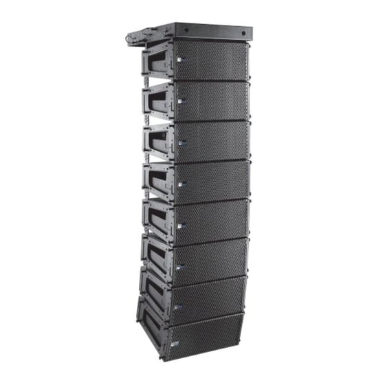
- Page 1 OPERATING INSTRUCTIONS LINE ARRAY LINA ™ Compact Linear Line Array Loudspeaker Keep these important operating instructions. Check www.meyersound.com for updates.
- Page 2 The contents of this manual are furnished for informational purposes only, are subject to change without notice, and should not be construed as a commitment by Meyer Sound Laboratories Inc. Meyer Sound assumes no responsibility or liability for any errors or inaccuracies that may appear in this manual.
-
Page 3: Important Safety Instructions
2. Keep these instructions. 12. Use only with the caster rails or rigging specified by 3. Heed all warnings. Meyer Sound, or sold with the apparatus. Handles are 4. Follow all instructions. for carrying only. 5. Do not use this apparatus near water. - Page 4 Wassereinwirkung oder übermäßig hoher Luft- feuchtigkeit ausgesetzt werden könnte, solange es sich nicht um ein Produkt handelt, dass mit der Meyer Sound English Weather Protection Option ausgestattet ist. • To reduce the risk of electric shock, disconnect the •...
- Page 5 LEOPARD OPERATING INSTRUCTIONS • Pour réduire les risques de surchauffe, évitez d’exposer Todas las demás reparaciones deben ser realizadas úni- directement l’enceinte aux rayons du soleil. Ne l’installez camente por personal de servicio capacitado de fábrica. pas à proximité de sources de chaleur, radiateur ou four par exemple.
- Page 6 IMPORTANT SAFETY INSTRUCTIONS...
-
Page 7: Table Of Contents
CONTENTS Important Safety Instructions Symbols Used Chapter 1: Introduction How to Use This Manual LINA Compact Linear Line Array Loudspeaker Native Mode Chapter 2: Power Requirements AC Power Distribution AC Connectors Wiring AC Power Cables Voltage Requirements Current Requirements Intelligent AC Power Supply... - Page 8 Appendix B: Rain Hoods Rigid Rain Hood Collapsible Rain Hood Appendix C: ULTRA Weather Protection Version Appendix D: LINA UW Rain Hood and Shield Attachment Parts List Ultra Weather Protect Rain hood and UW Shield installation Appendix E: Specifications Appendix F: Dimensions...
-
Page 9: Chapter 1: Introduction
In addition Tel: +1 510 486.1166 • to standalone implementations, LINA can also be used in a Tel: +1 510 486.0657 (after hours support) LEOPARD system as a supplemental fill loudspeaker. •... -
Page 10: Native Mode
1 to 11 degrees. Rigging options are shared with MINA and include the MG-MINA/LINA/750-LFC Multipurpose Grid (Figure 2), the MCF-MINA/LINA Caster Frame (Figure 3), the MYA-MINA/LINA Yoke and the MUB-MINA/LINA U-Bracket. Entire LINA family systems should be designed with Meyer Sound’s MAPP prediction software, which effectively... - Page 11 LINA OPERATING INSTRUCTIONS Audio Source Figure 6: Mixed Groundstack NOTE: Native mode should not be used with Audio Source more advanced configurations, such as those where 750-LFCs and LINAs are not coplanar, or those Figure 4: Flown Mixed Array requiring delay offsets to align subsystems or to create directional low-frequency control.
- Page 12 CHAPTER 1: INTRODUCTION...
-
Page 13: Chapter 2: Power Requirements
Figure 7 illustrates a basic 120 V AC, 3-phase Wye distribution safety guidelines is critical for the safe operation of LINA. system with the loudspeaker load distributed across all three phases, with each loudspeaker connected to a single line and common neutral and earth/ground lines. -
Page 14: Ac Connectors
AC Input (Blue) LINA ships with a gray powerCON 20 cable mount connec- The blue AC Input connector supplies power to LINA. The 3- tor, rated at 20 A, for assembling AC looping cables. conductor powerCON 20 is rated at 20 A and uses a locking Assembled 1-meter AC looping cables (PN 28.115.032.03) -
Page 15: Wiring Ac Power Cables
LINA OPERATING INSTRUCTIONS WIRING AC POWER CABLES VOLTAGE REQUIREMENTS LINA ships with a gray powerCON 20 cable mount connector, LINA operates as intended when receiving AC voltage within rated at 20 A, for assembling AC looping cables (Figure 11). the following range: The pins on the powerCON 20 cable mount connector are 90–264 V AC, 50–60 Hz... -
Page 16: Intelligent Ac Power Supply
Use the information in Table 3 to select the appropriate Powering on LINA cable gauge and circuit breaker ratings for the system’s When powering on LINA, the following startup events take operating voltage. place over several seconds. Table 3: LINA Current Draw 1. -
Page 17: Electrical Safety Guidelines
The powerCON 20 connector should not be engaged or • disengaged when under load or energized. Either de-energize or disconnect the other end of the cable. LINA requires a grounded outlet. Always use a grounded • outlet and plug. Earth ground... - Page 18 CHAPTER 2: POWER REQUIREMENTS...
-
Page 19: Chapter 3: Amplification And Audio Connectors
AUDIO CONNECTORS loop, class D amplifier. The audio signal is processed with elec- LINA is available with XLR 5-pin (Figure 14) or 3-pin connec- tronic crossover, and correction filters for flat phase and fre- tors (Figure 15) for audio Input and audio Loop output. XLR 5- quency responses, and by driver protection circuitry. -
Page 20: Trupower Limiting
Ω (10 k Ω / 10). To drive this number of looped loudspeakers, the source device should Ω or less. This same rule have an output impedance of 100 applies when looping LINAs with other Meyer Sound self- powered loudspeakers. NOTE: Most source devices are capable of driving loads no less than 10 times their output impedance. -
Page 21: Amplifier Cooling System
LINA OPERATING INSTRUCTIONS HF and LF Limit LEDs AMPLIFIER COOLING SYSTEM The low- and high-frequency drivers for LINA are powered by LINA is convection cooled. The amplifier’s heat sink provides separate amplifier channels, which have limiters. Limiting natural convection cooling from the air flowing near its fins. - Page 22 CHAPTER 3: AMPLIFICATION AND AUDIO CONNECTORS...
-
Page 23: Chapter 4: Quickfly Rigging
Required Release Pins Shackles MG-MINA/LINA/750-LFC 39 lb With some restrictions, flies up to 16 LINA cabinets at a 0.25 in x 0.90 in (black button), 5/8-inch or multipurpose grid kit (17.7 kg) 5:1 safety factor and BGV C1 with some angle restrictions PN 134.036, qty 8 included... -
Page 24: Lina Guidealinks
MTG-LEO-M, MTG-LYON, MTG-1100, and 7/8-inch MG-LINA/750 grids. MCF-MINA/LINA 28 lb Safely transports up to five LINA cabinets, making it 0.25 in x 0.90 in (black button), — caster frame kit (12.7 kg) easy to assemble and disassemble arrays in blocks of PN 134.036, qty 4 included... - Page 25 How the loudspeakers relate to the floor, stage, and seating angles in the venue depends on the orientation of the MG-MINA/LINA/750-LFC grid, the angles of the loudspeakers in the array above them, whether they are flown or ground-stacked, and other factors. Use MAPP...
-
Page 26: Mg-Mina/Lina/750-Lfc Grid
Figure 22: MG-MINA/LINA/750-LFC Grid The MG-MINA/LINA/750-LFC grid has four captive links, two per side, that attach to the top LINA in flown arrays. The configuration of the links and orientation of the grid (for either maximum uptilt or maximum downtilt) determine the –5°... - Page 27 “Maximum Uptilt.” The COG line is also useful when suspending the grid from a With the maximum uptilt orientation, the LINA at the top of the single center pickup point. Determine the appropriate point to array can be attached to the grid at –5 and –10° downtilt use by observing which one of the 11 pickup points the COG (Figure 24).
- Page 28 The LINA at the bottom of the stack attaches directly to the grid with its GuideALinks and is secured with the quick- release pins included with the grid (Figure 28).
-
Page 29: Mya-Mina/Lina Mounting Yoke
The bracket options allow the yoke to attach near the center of gravity for the loudspeakers. The brackets bolt directly to the LINA end frames with the M6 bolts and washers included with the yoke kit. For attaching to the... - Page 30 CHAPTER 4: QUICKFLY RIGGING Pole-Mounting LINAs with the MYA-MINA/LINA Up to two LINA loudspeakers can be pole-mounted with the MYA-MINA/LINA mounting yoke. For pole-mounting two LINA loudspeakers, use the MPA-2 bracket (Figure 34). For pole-mount applications, the yoke supports up to 30° of downtilt and severe uptilts of up to 90°.
-
Page 31: Mub-Mina/Lina U-Bracket
With the U-bracket, up to two LINA loudspeakers can also be flown from trusses using C-clamps or the equivalent. For flying and Floor- and Pole-Mounting LINAs with the... -
Page 32: Pbf-Lina Pullback Frame
PBF-LINA pull-back frame can be attached to the bottom cabinet in LINA arrays and pulled by a separate motor. The pull-back frame is secured to the bottom cabinet with the quick-release pins (0.25 in x 0.53 in, black button, PN 134.039) included with LINA. -
Page 33: Mcf-Mina/Lina Caster Frame
Assembly Guide (PN 05.207.101.02) available at www.meyersound.com. Figure 39: MCF-MINA/LINA Caster Frame The LINA at the bottom of the stack attaches securely to the caster frame with its GuideALinks and is secured with the four Figure 40: MCF-MINA/LINA Caster Frame with LINA Stack (1/4 by 0.90-inch) quick-release pins included with the caster... - Page 34 When transporting a non-curved LINA stack with 0° • splay angles, configure the rear GuideALinks for the bot- tom LINA so it is attached to the caster frame at 0° (using the 5° hole in the LINA GuideALinks). When transporting a curved LINA stack with wide splay •...
-
Page 35: Chapter 5: Rms Remote Monitoring System
RMServer is a compact, Ethernet-based hardware unit with two FT-10 RMS data ports. RMServer stores system configu- The LINA RMS user panel (Figure 43) includes an Identify but- rations internally, eliminating most manual data entry. Systems ton, Remote Mute switch, Wink/Activity LED, and two Network can be monitored from a computer at front-of-house or back- connectors. -
Page 36: Neuron Id For Rms Module
Compass RMS. RESETTING THE RMS MODULE Remote Mute Switch You can use the Identify button to reset the LINA RMS mod- The recessed Remote Mute switch on the LINA RMS mod- ule when powering on the loudspeaker. This action will ule (Figure 44) determines whether Compass RMS can con- cause the module to be removed from the RMS network. -
Page 37: Chapter 6: System Design And Integration Tools
CHAPTER 6: SYSTEM DESIGN AND INTEGRATION TOOLS This chapter introduces MAPP, Meyer Sound’s patented MAPP client software lets you configure Meyer Sound system design tool, and SIM, a comprehensive system for loudspeaker systems and define the environment in which measurement and analysis. -
Page 38: Sim Measurement System
• Measuring variations in frequency response caused by the acoustical environment and the placement and interaction Source Independent Measurement Technique of loudspeakers to determine corrective equalization The SIM audio analyzer implements Meyer Sound’s source • Optimizing subwoofer integrations independent measurement technique. This dual-channel • Optimizing loudspeaker arrays method makes analysis of statistically unpredictable excitation signals possible. -
Page 39: Appendix A: Meyer Sound Weather Protection
APPENDIX A: MEYER SOUND WEATHER PROTECTION The Weather Protection option from Meyer Sound is air environments, the exterior grille can quickly show signs intended to increase the useful life of Meyer Sound of oxidation, causing unsightly discoloration. loudspeakers when they are installed outdoors and exposed Apart from selecting suitable weather protection, the to different and often harsh weather conditions. -
Page 40: Weather Protection Components
Always discuss the environmental conditions of your Meyer Standard Weather Protection Sound installation with your Sales Manager, and verify the Meyer Sound designs toward an IP rating of IPX4 (see “IP availability of Weather Protection for your selected Ratings” on page 41) for Standard Weather Protection, loudspeaker models. -
Page 41: Ip Ratings
OPERATING INSTRUCTIONS IP RATINGS IP stands for “Ingress Protection.” The current format for expressing an IP rating is a 2-digit code. The first digit of an IP rating represents protection from solid objects. The second digit of an IP rating represents protection from water or moisture. - Page 42 APPENDIX A: MEYER SOUND WEATHER PROTECTION...
-
Page 43: Appendix B: Rain Hoods
A fixed rigid rain hood for permanent installations, a collapsible hood for portable applications, and an Ultra Weather Protection rain hood that has improved corrosion resistance (see Appendix C, “ULTRA Weather Protection Ver- sion” and Appendix D, “LINA UW Rain Hood and Shield Attachment”). Please specify the desired rain hood when ordering. RIGID RAIN HOOD The LINA rigid removable rain hood is easily attached and removed with the included four screws (Figure 46). -
Page 44: Collapsible Rain Hood
APPENDIX B: RAIN HOODS COLLAPSIBLE RAIN HOOD The LINA collapsible rain hood is installed on the unit when shipped. Four screws secure its frame permanently (Figure 47). Figure 47: LINA with collapsible rain hood To use the LINA collapsible rain hood: 1. -
Page 45: Appendix C: Ultra Weather Protection Version
Examples would include cruise ship exterior areas, ocean-side visitor attractions, swimming pool areas, and themed attractions with wind-carried water spray. For installations in extremely harsh environments, Meyer Sound offers an Ultra Weather Protection option for the LINA loudspeaker, which includes all of the components of standard Weather Protection, plus the following: •... - Page 46 APPENDIX C: ULTRA WEATHER PROTECTION VERSION...
-
Page 47: Appendix D: Lina Uw Rain Hood And Shield Attachment
(Figure 48). Do not cross cables Figure 48: LINA with Rain Hood and UW Shield (left) and Inside Rain Hood view of Cable Routing over Inner Wall (right) 1. Attach any required cables to the LINA loudspeaker. 2. Carefully route the cables, so that they wrap over and down the inner rain hood wall (see Figure 48, right), and exit through the slot. - Page 48 OPERATING INSTRUCTIONS Do not cross cables Figure 49: Routing Cables over Rain Hood (left) and Hooking Shield over Securing Screws (right) 7. Tighten the upper and lower screws on the left side of the rain hood (Figure 50). The recommended torque value for all four screws is 10–12 in-lbs (1.1-1.4 N·m).
- Page 49 CAUTION: There is only one proper loudspeaker orientation once the rainhood is installed. See Figure 48. CAUTION: The weather-protected LINA must be mounted with a 0 ° tilt, or preferably with a slight down-tilt. This angle shields the driver from the elements and does not allow water to accumulate. Do not tilt the cabinet up, as the drivers and cabinet will accumulate water.
- Page 50 OPERATING INSTRUCTIONS...
-
Page 51: Appendix E: Specifications
APPENDIX E: SPECIFICATIONS LINA loudspeaker system predictions for coverage and SPL are available in Meyer Sound’s MAPP System Design Tool, which can be found on the Meyer Sound website: http://www.meyersound.com. ACOUSTICAL 65 Hz – 18 kHz Operating Frequency Range Note: Recommended maximum operating frequency range. Response depends on load- ing conditions and room acoustics. - Page 52 Powder-coated, hex-stamped steel with acoustical black mesh Rigging End frames with captive GuideALinks secured with 0.25 in x 0.53 in quick release pins that allow 0° to 11° splay angles. M6 attachment points for optional MYA-MINA/LINA Mounting Yoke and MUB-MINA/LINA U-bracket. ENVIRONMENTAL Operating Temperature 0 °C to +45 °C...
- Page 53 LINA OPERATING INSTRUCTIONS Federal Communications Commission (FCC) Statement This equipment has been tested and found to comply with the limits for a Class A digital device, pursuant to part 15 of the FCC Rules. These limits are designed to provide reasonable protection against harmful interference when the equipment is operated in a commercial environment.
- Page 54 APPENDIX E: SPECIFICATIONS...
-
Page 55: Appendix F: Dimensions
[213 mm] 5.85 in 3.56 in [149 mm] [90 mm] 15.32 in [389 mm] For dimensions of the MG-MINA/LINA/750-LFC top grid and MCF-MINA/LINA/750 caster frame, refer to the MG- MINA/LINA/750-LFC Grid and Accessories Assembly Guide (PN 05.207.101.02) available at www.meyersound.com. -
Page 56: Lina Dimensions With Rain Hood
APPENDIX F: DIMENSIONS LINA DIMENSIONS WITH RAIN HOOD 20.27 in [515 mm] 7.60 in [193 mm] 3.75 18.53 in [95 mm] [471 mm] 8.38 in 10° [213 mm] 5.85 in 3.56 in 4.19 [149 mm] [90 mm] [106 mm] 18.95 [481 mm] 15.32 in... - Page 58 Meyer Sound Laboratories Inc. © 2019 2832 San Pablo Avenue Meyer Sound Laboratories Inc. All rights reserved. Berkeley, CA 94702 LINA Operating Instructions +1 510 486.1166 PN 05.270.005.01 B www.meyersound.com...
Need help?
Do you have a question about the LINA and is the answer not in the manual?
Questions and answers