urmet domus 1083 Manual
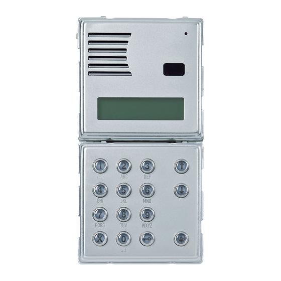
2voice digital call module
Hide thumbs
Also See for 1083:
- User manual ,
- Configuration booklet (152 pages) ,
- System booklet (100 pages)

Related Manuals for urmet domus 1083


Summary of Contents for urmet domus 1083
- Page 1 Mod. 1083 DS 1083-035B LBT 8757 MODULO DI CHIAMATA DIGITALE 2VOICE 2VOICE DIGITAL CALL MODULE Sch./Ref. 1083/19...
-
Page 2: Installazione
Programmabile tramite dispositivi portatili via Bluetooth dotati di software dedicato. INSTALLAZIONE Il modulo di chiamata Sch.1083/19 è dedicato al sistema 2Voice. È realizzato su meccanica Sinthesi a 2 moduli e prevede una tastiera a 15 tasti e un display a 32 caratteri. - Page 3 • Posizionare la cornice sul telaio • Serrare le viti B sulle viti A DS1083-035B...
- Page 4 DESCRIZIONE MORSETTI / PREDISPOSIZIONI Riferimento per segnale telecamera di controllo / commutatore video Segnale telecamera di controllo / commutatore video Azionamento elettroserratura pedonale Positivo azionamento elettroserratura pedonale con scarica capacitiva Negativo azionamento elettroserratura pedonale con scarica capacitiva Non usare LINE Linea Bus entrante Riferimento per commutatore video Comando per commutatore video Riferimento per PA e SP...
- Page 5 ROSSO - Positivo di alimentazione (+TC) NERO - Negativo di alimentazione (R1) BIANCO - Cavo coassiale per segnale video (V3, V5) Led della telecamera spenti Sch. 1083/19 Led della telecamera accesi (default) Sch. 1748/40 V3 - V5...
- Page 6 PROGRAMMAZIONE DELLA CONFIGURAZIONE Il menu di confi gurazione è così composto: Uscita dalla CONFIGURAZIONE programmazione TIPO MODULO <PRI> <SEC> Solo se secondario ID MODULO SECONDARIO <0> <1> TIPO CODICE <FISI> <LOGIC> TIPO DISPOSITIVO <AUDIO> <VIDEO> TEMPO OCCUPATO INTERROMPIBILE <SI> <NO> In caso di inserimento valori non validi, compare la videata T APRIPORTA 1...
- Page 7 ID ma numero diverso (v. parametro successivo). – L’ID del posto esterno secondario deve coincidere con l’ID di colonna impostato nell’interfaccia di colonna 1083/50. • Secondario Se il Tipo modulo è secondario e nella stessa colonna c’è un solo secondario, impostare 0; se ce ne sono 2 impostare 0 e 1 nei due secondari.
- Page 8 • T Apriporta 1 È il tempo di mantenimento dell’elettroserratura pedonale (morsetti SE+/SE-) e di attivazione dei morsetti C/NC/NO. Il numero digitabile (espresso in secondi) è compreso tra 1 e 90. • Tipo apriporta 1 L’elettroserratura può essere gestita in modalità ‘sotto segreto’ o ‘libero’. Il comportamento del posto esterno è...
- Page 9 CODICE FISICO: Inserire il codice fi sico di chiamata dell’appartamento nel formato XYABC dove XY è la colonna (00-31) e ABC è l’indirizzo dell’appartamento (0-127). In impianti senza interfaccia di colonna Sch. 1083/50 il codice di colonna è 00. Premendo si passa al passo successivo (codice logico oppure codice apriporta).
- Page 10 Premendo il tasto X si cancella il codice. Premendo il tasto X in assenza di caratteri inseriti, si torna al passo precedente. In caso di inserimento di un codice non valido, compare un messaggio di errore ed è necessario reinserire il dato.
- Page 11 PROGRAMMAZIONE DEI CODICI APRIPORTA In questo menù è possibile gestire i codici apriporta non legati ai nominativi della rubrica. Il menù è così composto: INSERISCI MODIFICA CANCELLA CANCELLA TUTTO Con i tasti freccia è possibile scorrere il menù di programmazione codici apriporta; con il tasto X, si esce dalla programmazione.
- Page 12 Se il modulo di chiamata è confi gurato a codici fi sici, inserire il codice di 5 cifre così composto: ccnnn, dove cc indica la colonna (da 00 a 31) e nnn indica il numero dell’appartamento (da 000 a 127). In impianti senza interfaccia di colonna Sch. 1083/50 il codice di colonna è 00. Sul display compaiono le cifre digitate:...
- Page 13 LINEA OCCUPATA ATTENDERE Quando il sistema torna libero, è possibile richiamare. E’ possibile digitare un codice fi sico che inizia con degli zeri omettendoli (ad esempio il codice fi sico 1001 chiamerà la colonna 01 utente 001). CHIAMATA TRAMITE DIGITAZIONE CODICE LOGICO Se il modulo di chiamata è...
- Page 14 nominativo che comincia con la lettera digitata; ricercare il nome desiderato con i tasti freccia. • Per esempio, per cercare il nome “ROSSI”, dalla visualizzazione precedente, premere il tasto 7 tre volte per posizionare la rubrica sul primo nome che inizia con la “R”; in mancanza di nomi che iniziano con la lettera “R”, il display si posiziona sul primo nominativo seguente in ordine alfabetico.
- Page 15 Continuando a tenere premuto il tasto 0 per 2s, il modulo di chiamata passa in modalità codici speciali e compare la scritta: CODICE SPECIALE: Inserire il codice di 3 cifre (da 1 a 255) programmato nella decodifi ca speciale da comandare. Il display visualizza tale codice con degli *: CODICE SPECIALE: 0***...
-
Page 16: Caratteristiche Tecniche
Si può uscire dalla programmazione Bluetooth premendo il tasto X per 2 secondi. DICHIARAZIONE DI CONFORMITÀ ALLA DIRETTIVA 1999/5/CE Con la presente URMET S.p.A. dichiara che il modulo di chiamata 2Voice Sch. 1083/19 è conforme ai requisiti essenziali ed alle altre disposizioni pertinenti stabilite dalla direttiva 1999/5/CE. -
Page 17: Panel Installation
Bluetooth programmable using portable devices equipped with dedicated software. PANEL INSTALLATION The Ref. 1083/19 call module is dedicated to the 2Voice system, is based on 2-module Sinthesi mechanics and comprises a 15-key keypad and 32-character display. A Ref. 1748/40 (colour) camera module can be associated with the digital call module to set up video door phone call stations. - Page 18 • Position the panel on the frame. • Fasten the screws B on screws A. DS1083-035B...
- Page 19 DESCRIPTION OF TERMINALS / SETTINGS Reference for control camera signal / video switch Control camera signal / video switch Activation main entrance electric lock Positive activation main entrance electric lock with capacitance discharge Negative activation main entrance electric lock with capacitance discharge Do not use LINE Bus line in Reference for video switch...
- Page 20 A 3-wire connector is provided for connecting the Ref. 1748/40 (colour) camera module to the back of the calling module: RED - Power positive (+TC) BLACK - Power negative (R1) WHITE - Video signal coax (V3, V5) Camera leds off Ref. 1083/19 Camera leds on (default) Ref. 1748/40 V3 - V5 System with coaxial cable PROGRAMMING Enter the code 99999 to access the confi...
-
Page 21: Configuration Programming
CONFIGURATION PROGRAMMING The confi guration menu is as follows: CONFIGURATION Exit programming MODULE TYPE <PRI> <SEC> Only if secondary MODULE ID SECONDARY <0> <1> CODE TYPE <PHYS> <LOGIC> DEVICE TYPE <AUDIO> <VIDEO> BUSY TIME STOPABLE <YES> <NO> If the value entered is not correct, the display shows DOOR LOCK T1 CODE NOT... -
Page 22: Configuration Parameters
Two main stations cannot have the same ID. Two secondary stations may have the same ID but must have a different number (see next parameter). – The ID of the secondary door unit must be the same as the riser column ID set in the Ref. 1083/50 riser column interface. •... - Page 23 • Door opener 1 Electric lock control may be “protected by privacy feature” or “unrestricted”. The door unit behaves as follows in the two cases: – ‘Private’: pressing the door-opener button of an apartment station, the electric lock of the call station is released only if a call has been received or a voice conversation is in progress with this or if, following auto power-on, it is in video connection with this.
-
Page 24: Name Programming
Enter the physical call code of the apartment in the format XYABC, where XY is the riser column (00-31) and ABC is the address of the apartment (0-127). In systems without Ref. 1083/50 riser column interface, the riser column code is 00. - Page 25 If the code entered is not valid, an error message is displayed and the data must be re-entered. LOGICAL CODE: If the device is set with code type = physical codes, this screen page is not displayed. Enter the logical call code of the apartment which must be a a number of 1 to 4 digits from 1 to 9999. Press to move to the door-opener code.
- Page 26 Enter the door-opener code which must be a 4-digit number from 0001 to 9999. A code between 1 and 4999 will open the main entrance; a code between 5000 and 9999 will open the vehicle entrance. After insertion, press Press X to cancel the code. Pressing X without inserting characters returns to the previous step. If the code entered is not valid or already exists, an error message is displayed and the data must be re- entered.
- Page 27 If the call module is confi gured with physical codes, enter the 5-digit code as follows: ccnnn, where cc indicates the riser column (from 00 to 31) and nnn indicates the number of the apartment (from 000 to 127). In systems without Ref.1083/50 riser column interface, the riser column code is 00. The digits entered are displayed:...
- Page 28 If the code is valid but the system is busy, the display shows: LINE BUSY WAIT When the system is free again, the call can be repeated. CALL BY SELECTING NAME FROM REPERTORY Press the arrow keys to scroll the list of names in alphabetical order. The names are shown on the display: ROSSI MARIO...
-
Page 29: Lock Management
COMMUNICATION AND DOOR OPENING If a call is made, when the user lifts the hand-set, the module establishes a conversation and for the entire communication time (max. 10 minutes) the display shows: SPEAK PLEASE If the user presses the button to open the main or vehicle entrance, the module activates the corresponding output with temporary display of: COME IN PLEASE... - Page 30 To exit Bluetooth programming, press X for 2 seconds. DECLARATION OF CONFORMITY TO DIRECTIVE 1999/5/EC Hereby Urmet S.p.A., declares that this 2Voice Digital call module Ref. 1083/19 is in compliance with the essential requirements and other relevant provisions of Directive 1999/5/EC.
-
Page 31: Technical Specifications
TECHNICAL SPECIFICATIONS 36 – 48 Vdc Power voltage (LINE): 36 – 48 Vdc Power voltage (+ -): Stand-by consumption: Max 85 mA Max. consumption (Video call) 220 mA Lock output SE+ SE-: capacitance discharge 22-24 Vdc + holding current max 200 mAdc Max 24 V 5A Lock relay C/NC/NO: Max 24 V 300 mA... - Page 32 DS 1083-035B LBT 8757 URMET S.p.A. Area tecnica 10154 TORINO (ITALY) servizio clienti +39 011.23.39.810 VIA BOLOGNA 188/C http://www.urmet.com Telef. +39 011.24.00.000 (RIC. AUT.) e-mail: info@urmet.com +39 011.24.00.300 - 323...
Need help?
Do you have a question about the 1083 and is the answer not in the manual?
Questions and answers