Table of Contents
Advertisement
Advertisement
Table of Contents

Related Manuals for MAI M400NT

Summary of Contents for MAI M400NT
- Page 1 AI PUMP AI PUMP OPERATING INSTRUCTION OPERATING INSTRUCTION CERTIFIED...
- Page 2 MAI International GmbH © Copyright 2003 V20/10/03 Page...
-
Page 3: Table Of Contents
MAI International GmbH LIST OF CONTENTS List of contents..............................3 Foreword ................................4 User-friendly ................................4 Operating instructions ............................4 Potential hazards..............................4 Warranty and liability ............................5 Prescribed use of the machine ..........................5 Improper use................................5 Personal safety ..............................5 Safety devices................................6 General safety instructions ..........................6 Copyright................................6 General ...................................7... -
Page 4: Foreword
The most important features of the MAI pump m400NT are the high quality of the components The MAI pump m400NT is built to the state of the used, the user-friendly layout of the controls and the art and in accordance with recognized safety regu- rugged design which proves its worth, day in and lations. -
Page 5: Warranty And Liability
PRESCRIBED USE OF THE ontract at the latest. MACHINE rranty and liability claims in The prescribed use of the MAI pump m400NT is for e event of personal injury or mixing and pumping commercially pre-mixed, ma- aterial damage... -
Page 6: Safety Devices
(e.g. padlock on master switch). written permission of MAI International GmbH. When components are replaced, the purchaser must ensure that the safety devices are fitted again Copies of individual parts may be made and passed properly. -
Page 7: General
MAI m400NT mortar mixing pump. NOTE The prerequisite for the use of the machine is a thorough knowledge of the technical documentation... -
Page 8: Training Record
MAI International GmbH TRAINING RECORD HAZARDS OF ELECTRICITY PERSON 1. Work on the electrical supply may only be car- ried out by authorized electricians. Inspect the Person Person Elec- Superior machine’s electrical system regularly. Obvious trained with trician with defects, such as loose connections, singed ca-... -
Page 9: General Safety Regulations
We also pump conforms Protection wish to point out that only original MAI spare Class IP44 in accordance with DIN parts may be used in the machine. 40050 and may not be cleaned DANGER with water jets. -
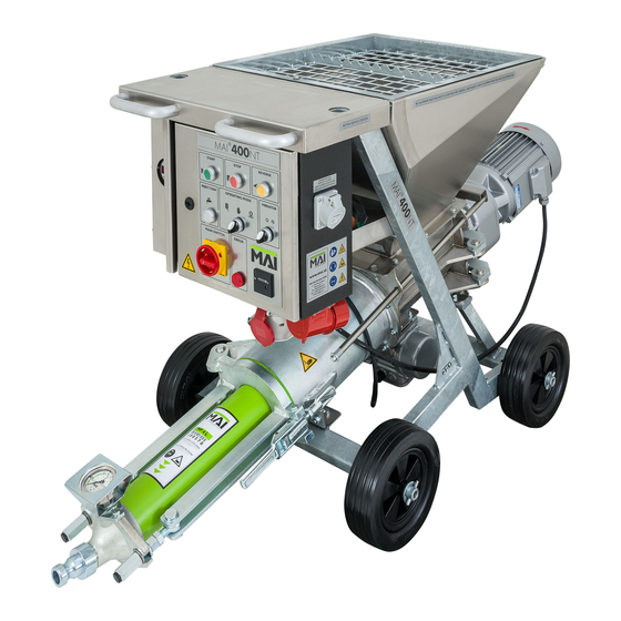
Page 10: Machine Views
MAI International GmbH 19. The mixer motor must not be switched on when 12. Before starting the machine, ensure that ma- it is tilted. chine-processable, easily workable mortar is being used, the hose is not leaking anywhere, 20. When you fill the dry mortar in the hopper it can especially at the unions, and the inside of the come to strong dust formation. -
Page 11: Operating Panel And Indicators
“STOPS” or shuts-off the machine when When on “Injection” the machine can be running or ready for operation operated with the Mai Injection pressure switch Mode switch vibrator: „0FF – ON“ The vibrator, located on the mixing chamber Green button of the mortar mixing pump, prevents the dry „STARTS“... -
Page 12: Main Dimensions
NW 35 max. 200 Mortar hose All the figures quoted Steel reinforced here refer to MAI prod- hose NW 25 and ucts and MAI hoses NW 35. Burst pres- only. sure = 160 bar Water pump No self priming pump... -
Page 13: Technical Descripton
For particularly large volumes the MAI pump these efficient, economical solutions. m400NT can also be fitted with the MP 12 conver- sion kit. The MAI pump m400NT is successfully in use all over the world –... -
Page 14: Filter Parts
MAI International GmbH FILTER PARTS Pressure reducing valve „water system“ Filter for mud Setting range: 1 – 2 bar Max. water flow at 1 bar approx. 800 l/h INITIAL SETTINGS Max. water flow at 2 bar approx.1300 l/h Pressure sensor „water system“... -
Page 15: Transport Weight & Dimensions
MAI International GmbH TRANSPORT WEIGHT & DI- MENSIONS Pump unit D... approx. 500 mm E... approx. 320 mm A... approx. 1040 mm Weight of components approx. 27 kg B... approx. 570 mm C... approx. 955 mm Weight of components approx. 130 kg Drive unit F... -
Page 16: Controls
MAI International GmbH horizontal and stable so that it cannot slip if moved accidentally. CONTROLS Check that all the cables and safety devices are functioning correctly. 1... Plug for remote control 2... Vibrator switch 3... Switch for Remote Control – Hand – Injec- tion 4... -
Page 17: Connections Before Start-Up
MAI International GmbH CONNECTIONS BEFORE START-UP Connect the main power plug on the control cabinet with the cable to the construction site distribution board. Plug the drive motor into the socket on the control cabinet. Connect the water supply hose (use a minimum diameter of ¾”) to the coupling in the water system. - Page 18 MAI International GmbH Turn mode switch “REMOTE-HAND- INJECTION” to position “HAND”. The vibrator switch must be set on “ON” to prevent the dry mate- rial from bridging at the bottom of the material hop- per. Undo the eccentric clamp on the mixing chamber.
- Page 19 MAI International GmbH While the machine is running, open the slide gate, Switch of the machine by pressing the red “STOP” located above the motor, slowly and in stages until button. it locks into the guide rod notch. To prevent chocking, we recommend wetting the inside walls of the hose with water or preferably lime or cement slurry.
-
Page 20: Start-Up For Manual Operation
MAI International GmbH Start-up for manual operation Start-up with remote control Proceed as described in the previous section “Start- Proceed as described in the previous section “Start- up”. up”. Make sure that the mode switch “REMOTE C – Make sure that the mode switch “REMOTE C –... -
Page 21: Interruptions And Downtime
MAI International GmbH During the operation of the ma- TERMINATION OF WORK AND chine with the remote control not CLEANING instructed persons in the direct danger area of the machine may WARNING not be! After work is completed or in the event of longer interruptions, run the machine until the material hopper is empty and then clean it thoroughly. -
Page 22: Machine Maintenance
The mechanical and electrical condition of the ma- CAUTION chine must be inspected by qualified personnel at least once a year. The MAI pump m400NT complies with the provisions of Protection PROCEDURE IN THE EVENT Class IP44 in accordance with DIN... -
Page 23: Transport
Drain any residual water from the mortar hoses and There are no lifting pins on the all other components. MAI pump m400NT for transport- ing by crane. If it has to be lifted by Assemble the machine again. crane, ensure that it is placed in a... -
Page 24: Checklist For Remedying Faults
MAI International GmbH CHECKLIST FOR REMEDYING FAULTS FAULT: Machine will not start Possible causes Fault remedy Dirt in control cabinet; power cable too long Have contactor replaced by a qualified elec- Contactor defective or does not pick up or cable diameter too small; stand-by gen- trician;... -
Page 25: Main And Control System Circuit
MAI INTERNATIONAL GmbH MAIN AND CONTROL SYSTEM CIRCUIT 2 4 6 1,6A 1 3 5 2 4 6 97 95 98 96 INTERNATIONAL Ersteller Zeichnungs-Nr. Blatt M400 Steuerstrom 2. Prototyp © Copyright 2003 V20/10/03 Page... -
Page 26: Spare Parts
Motor flange galvanized 153526 Bolt for eccentric tensioner MF 152650 Eccentric tentioner 152774 Sealing motor flange 152662 MAI-Plastic screw ø=140 100033 Mixer versatile ø140 L=305mm 153227 Sealing for pump flange 153348 Hexagonal nut M16 L=48 galvanized 153408 Hexagonal nut with flange M16 galvanized... - Page 27 Attachment parts Japan complete 102960 Wheel 250x80 153313 Wheels for NT-Series 153578 Attachment parts runner complete 152783 153396 E-System 6KW M400NT 200/220V 50Hz/60Hz 153658 E-System 6KW M400NT 440-460V50Hz 17.01 w/o Fig. 152763 Proximity sensor with cable 153386 Cover plate front for watersystem 153235...
- Page 28 MAI INTERNATIONAL GmbH SPARE PARTS "FIGURE B" Pos. Description 102826 Gear set FG132, 20/61 102737 Gear set G132, 23/58 1.01 w/o Fig. 151549 Gear set 2. level FG132 200 min-¹, Z14/67 1.02 w/o Fig. 100018 Spur gear FG132 6 kW, 200 min-¹...
- Page 29 MAI INTERNATIONAL GmbH SPARE PARTS "FIGURE C" Pos. Description 152752 PU Mixing-tube 152784 Mixing-tube galvanized 152792 Nozzle plate complete 152771 Water jet body PU 152764 Sealing gasket PU 153545 Nozzle body complete with 1/2" nipple 101213 Elbow 1/2" IT galvanized 100247 Nozzle 1/2"...
- Page 30 MAI INTERNATIONAL GmbH SPARE PARTS "FIGURE D" Pos. Description 100252 Glycerin gauge 6 bar 153610 Water flowmeter 1/2" 2500l 2.01 w/o Fig. 153762 Water flowmeter 1/2" with cable 2.02 w/o Fig. 153642 Connection cable for water flow meter 100391 Water dosing valve 3/4" 110 MS 5 3.01 w/o Fig.
- Page 31 MAI INTERNATIONAL GmbH 9.03 w/o Fig. 151069 Plastic cap 1/4" 9.04 w/o Fig. 151206 Sealing ø18.5 - ø23.5 x 2 mm 103122 Nozzle 3/4" with external thread 100328 Rubber hose 3/4" black 100223 GEKA coupling 3/4" internal thread 12.01 w/o Fig.
- Page 32 MAI INTERNATIONAL GmbH SPARE PARTS "FIGURE E" Pos. Description 100252 Glycerin gauge 6 bar 102915 Spacer for water flow meter 1000 ltrs./h 152559 Solenoid valve NC 1/2" NW13 42 V /50Hz 3.01 w/o Fig. 153761 Solenoid valve with cable NC 1/2" NW13 42V/50Hz 153606 Flow meter 1300 ltrs./h...
- Page 33 MAI INTERNATIONAL GmbH SPARE PARTS "FIGURE F" Pos. Description 101489 Ball valve 1/2" 1.01 w/o Fig. 151302 Handle for ball valve 100181 GEKA coupling 1/2" external thread 153517 MAI-Quick coupling NW25 1/2" "male" © Copyright 2003 V20/10/03 Page...
- Page 34 MAI INTERNATIONAL GmbH SPARE PARTS "FIGURE G" Pos. Description 151066 Connector angular 32A 5 poles 400V 101188 Socket 32A 4pole 400V 100025 Socket 16 A 5poles 400V 151728 Indicator light lens assembly M22-L-R red 151594 Selector switch 3 Stellungen M22-WRK3...
- Page 35 MAI INTERNATIONAL GmbH SPARE PARTS "FIGURE H" Pos. Description 150961 Main switch P1-32/EA/SVB 32A 1.01 w/o Fig. 153262 Mainswitch P3-63/EA/SVB 6-7,5kW Japan 151597 Fixed adaptor M22-A 152356 LED-Element red M22-LED-R 18-30V 151597 Fixed adaptor M22-A 151599 Contact element 1Ö M22-K01...
- Page 36 MAI INTERNATIONAL GmbH SPARE PARTS "FIGURE I" Pos. Description 152756 Switch cabinet 1.01 w/o Fig. 152521 Cover for switch cabinet 150739 Auxiliary contactor 400V/50-60Hz 152759 Motor protection switch PKM0-16 104044 Motor protection relay PKZM 0-1,6, 1-1,6A 102126 Phase sequence relay RM4TG20...
- Page 37 MAI INTERNATIONAL GmbH SPARE PARTS "FIGURE J" Pos. Description 152756 Switch cabinet 1.01 w/o Fig. 152521 Cover for switch cabinet 153263 Auxiliary contactor 220V/50-60Hz 153255 Motor protection switch 32A 104044 Motor protection relay PKZM 0-1,6, 1-1,6A 102126 Phase sequence relay RM4TG20...
- Page 38 Pump outlet "M" galvanized M400NT 100279 MAI-Quick coupling NW25 1" "male" 153516 MAI-Quick coupling NW25 6/4" "male" 151097 Kamlok coupling NW25 "male" 100231 MAI-Quick coupling NW35 6/4" "male" 153640 Pump outlet "M" galvanized M400NT Japan © Copyright 2003 V20/10/03 Page...
- Page 39 MAI INTERNATIONAL GmbH © Copyright 2003 V20/10/03 Page...
Need help?
Do you have a question about the M400NT and is the answer not in the manual?
Questions and answers