
Related Manuals for Velux KFX 210


Summary of Contents for Velux KFX 210
- Page 1 KFX 210/211/212/213/214 KFC 210/220 Instructions for VELUX control system for smoke ventilation ENGLISH VAS 453812-2019-11...
- Page 2 2 VELUX ®...
-
Page 3: Table Of Contents
KFC to another - Ventilation switch - Rain sensor - Receive alarm from a primary, external control system - Transmit alarms or error indications to other external equipment Replacement of frame in control unit Technical data VELUX ®... -
Page 4: Important Information
Safety • Control system for smoke ventilation KFX 210/211/212/213/214 and control unit for smoke ventilation KFC 210/220 can be used by persons (aged 8 years and above) with sufficient experience and knowledge if they have been given instruction concerning safe use and understand the hazards involved. - Page 5 Important information Product • The control system has been designed for use with genuine VELUX prod- ucts. Connection to other products may cause damage or malfunction. • The control system is in conformity with the Low Voltage Directive and the EMC Directive for use in household, trade, industry and light industry.
- Page 6 VELUX A/S: ........
- Page 7 VELUX ®...
-
Page 8: Contents Of Packaging
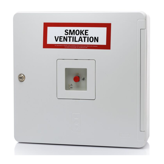
Blank lid unit. Break-glass point Frame with instructions KFK 100-104*) Keys, rubber bushes, screws Smoke detector KFA 100*) and cable ties Coloured frame*) Labels *) Is delivered depending on type Back-up batteries of control system. 8 VELUX ®... - Page 9 Stick the supplied label "SMOKE VENTILATION" onto the indicated area on the control unit. Keep the instructions behind the battery holder in the control unit. VELUX ®...
-
Page 10: Overview Of Printed Circuit Board
MOTOR 1 MOTOR 2 ALARM LINK DET. DET. 230V 230V Mains connection Ventilation switch 13, 25 Motor 1 14-15 Break-glass point Motor 2 14-15 Alarm signals 23-24, 27-28 Smoke detector Link Rain sensor Rain signal - output 10 VELUX ®... - Page 11 FUSE: 25A ERROR-SMOKE DET. RESET ERROR-BREAK GLASS – ERROR-TEMP. FUSE ALARM AC TIVE BAT TERY Rain signal - input Auto close time FACU terminals 23, 27 Temperature fuse Error indication Status indications 20-22 Batteries Setting Comfort opening time VELUX ®...
-
Page 12: Break-Glass Point Kfk 100
Colour of frame for break-glass point in control unit The white frame can be replaced by the coloured frame supplied (applies to KFX 211, 212, 213 and 214 and KFC 210 and 220). See page 32. 12 VELUX ®... -
Page 13: Smoke Detector Kfa 100
The terminal module in the control unit must be L1 in moved to the last or only smoke detector – ie to the smoke detector placed farthest away from L1 out the control unit. L1 in L1 out SMOKE VELUX ®... -
Page 14: Rain Sensor Kla 200
2 minutes before the comfort ventila- tion can be activated again. RAIN When connecting, lead cable through the rub- ber membrane and fasten with cable tie. 14 VELUX ®... -
Page 15: Ventilation Switch Kfk 200
Automatic closing of windows opened for comfort ventilation purposes can also be set. This function is only active if switch 4 is set in position ON (see page 19). Min opening time: 2 minutes Max opening time: 60 minutes VELUX ®... -
Page 16: Motor Terminals
GGL/GGU -K-- ----40 or CSP and the cables from the control unit. Note: In case motors operate in the wrong direc- tion, transpose the 2 motor cables in the terminal. MOTOR 1 DET. MOTOR 1 DET. 16 VELUX ®... -
Page 17: Wiring
3 x 2.5 mm 14 m *) 5 x 2.5 mm 28 m 3 x 4 mm 22 m 3 x 6 mm 33 m *) 2x2 conductors in parallel Only one smoke ventilation window CSP per motor terminal VELUX ®... -
Page 18: Setting Of Switches
(Factory setting). If an alarm is activated via a smoke detector, all windows that are open (in comfort ventilation position) close. Note: If an alarm is activated via a break-glass point, all windows open. 18 VELUX ®... - Page 19 Note: When the battery is low, the light-emitting diode flashes on and off. If the service technician decides to turn off the diode, the battery monito- ring is also off. Battery monitoring is off. Switch 6 N/A (No function) N/A (No function) VELUX ®...
-
Page 20: Operation Of And Signals From Control Unit
See section Ventilation switch KFK 200. Note: If a rain sensor is fitted, the comfort ventilation function will automatically be blocked if rain is detected. 20 VELUX ®... -
Page 21: Back-Up Batteries
The printed circuit board monitors the status of the back-up batteries. If the control unit is being supplied with power from the back-up batter- ies, the yellow light-emitting diode flashes on and off showing that the 230 V mains supply is interrupted. Install battery holder. VELUX ®... -
Page 22: Mains Connection
Take all necessary actions to comply with current local requirements (contact a qualified electrician, if necessary). 230V/50Hz Lead cable as shown and fasten it in cable gland. For optimum fixing, the rubber bush can be replaced by one of the rubber bushes supplied. 22 VELUX ®... -
Page 23: Status And Error Indication In Control System
Exceeded service intervals are also error indicated with a yellow light-emitting diode in the integrated break-glass point and possible additional break- glass points and an acoustic alarm. VELUX ®... - Page 24 If the cable to the connected smoke detector(s) is interrupted, the yellow light-emitting diode flashes on and off. If the cable is short-circuited, the yellow light-emitting diode is on permanently. The error is also indicated in the integrated break-glass point and pos- sible additional break-glass points. 24 VELUX ®...
- Page 25 ERROR - COMFORT VENTILATION After an alarm or a power failure, it will take at least 2 minutes before the comfort ventilation can be activated again. VELUX ®...
-
Page 26: Connected Control Units
2 to the FACU terminal in control unit 3 etc. Note: In control unit 2 and possible additional control units, dip switch no. 2 is set in position ON. ALARM ALARM FACU FACU + – + – Control unit 1 Control unit 2 Control unit 3 26 VELUX ®... -
Page 27: Receive And Transmit Error Indications From One Control Unit Kfc To Another
Indication of the specific error can be seen on the printed circuit board of the control unit where the error has occured. LINK LINK LINK Control unit 1 Control unit 2 Control unit 3 VELUX ®... -
Page 28: Ventilation Switch
Up to 10 control systems can be connected. COMFORT COMFORT Control unit 1 Control unit 2 Note: Do not connect the control systems if you would like a local ventilation switch. COMFORT COMFORT Control unit 1 Control unit 2 28 VELUX ®... -
Page 29: Rain Sensor
The example below shows a cable connection with several control systems but only one rain sensor. RAIN OUT RAIN IN RAIN OUT RAIN IN FACU ERROR SMOKE RAIN + – Control unit 2 Control unit 1 VELUX ®... -
Page 30: Receive Alarm From A Primary, External Control System
24 V DC or 48 V DC through the relay. Note: Do not overload the 24 V outlet with other additional connections. Fire Alarm Control Unit FACU ALARM FACU + – + – 30 VELUX ®... -
Page 31: Transmit Alarms Or Error Indications To Other External Equipment
An alarm will be transmitted from the ALARM terminal where a potential-free relay switches in case of alarm. Error indications will be transmitted from the ERROR terminal where a potential-free relay switches in case of alarm. ERROR ALARM VELUX ®... -
Page 32: Replacement Of Frame In Control Unit
The white frame of the control unit can be replaced by the coloured frame supplied (applies to KFX 211, 212, 213 and 214 only). Remove white frame as shown. 2 3 4 5 6 Place glass from the white frame in the coloured frame. Fit the coloured frame. 32 VELUX ®... -
Page 33: Technical Data
− Without batteries: 3.1 kg − With batteries: 8.0 kg Weight KFC 220: − Without batteries: 3.7 kg − With batteries: 8.6 kg Cabinet colour: RAL 9016, white Maintenance: Once a year or according to local requirements (service timer 15 months) VELUX ®... - Page 34 34 VELUX ®...
- Page 35 VELUX ®...
- Page 36 VELUX Italia s.p.a. 02245/32 3 50 045/6173666 VELUX Australia Pty. Ltd. VELUX-Japan Ltd. 1300 859 856 0570-00-8141 VELUX Bosna i Hercegovina d.o.o. VELUX International (VELUX A/S) 033/626 493, 626 494 +45 7632 9240 VELUX Belgium VELUX Lietuva, UAB (010) 42.09.09 (85) 270 91 01 ВЕЛУКС...
Need help?
Do you have a question about the KFX 210 and is the answer not in the manual?
Questions and answers