
Related Manuals for WAGO 750-333/040-000


Summary of Contents for WAGO 750-333/040-000
- Page 1 Manual WAGO I/O SYSTEM 750 XTR 750-333/040-000 FC PROFIBUS G2 12MBd XTR Fieldbus Coupler PROFIBUS DP; 2. Generation; 12 MBd; Extreme Version 1.4.0...
- Page 2 We wish to point out that the software and hardware terms as well as the trademarks of companies used and/or mentioned in the present manual are generally protected by trademark or patent. WAGO is a registered trademark of WAGO Verwaltungsgesellschaft mbH. Manual Version 1.4.0...
-
Page 3: Table Of Contents
WAGO I/O SYSTEM 750 XTR Table of Contents 750-333/040-000 FC PROFIBUS G2 12MBd XTR Table of Contents Notes about this Documentation ............. 8 Validity of this Documentation..............8 Copyright ....................8 Symbols ....................9 Number Notation .................. 11 Font Conventions ................. 11 Important Notes .................. - Page 4 Table of Contents WAGO I/O SYSTEM 750 XTR 750-333/040-000 FC PROFIBUS G2 12MBd XTR Device Description .................. 46 View ..................... 47 Connectors ................... 49 4.2.1 Device Supply .................. 49 4.2.2 Fieldbus Connection ................ 50 Display Elements .................. 51 Operating Elements ................52 4.4.1...
- Page 5 WAGO I/O SYSTEM 750 XTR Table of Contents 750-333/040-000 FC PROFIBUS G2 12MBd XTR 8.4.1 Application Example ................ 89 8.4.1.1 Physical station design with deactivated parameter “Startup if expected and actual configuration differ” ..............91 8.4.1.2 Physical station design with activated parameter “Startup if expected and actual...
- Page 6 Table of Contents WAGO I/O SYSTEM 750 XTR 750-333/040-000 FC PROFIBUS G2 12MBd XTR 12.1 Configuration Identifiers ..............133 12.1.1 Fieldbus Coupler ................133 12.1.2 Digital Input Modules..............133 12.1.3 Digital Output Modules ..............135 12.1.4 Power Supply Modules ..............136 12.1.5...
- Page 7 WAGO I/O SYSTEM 750 XTR Table of Contents 750-333/040-000 FC PROFIBUS G2 12MBd XTR ® 12.3.2.13 Parameters of the Bluetooth RF Transceiver ......218 12.3.2.14 Parameters of the MP-Bus Master Module ........ 219 12.3.2.15 Parameters of the 2-channel Vibration Velocity / Roller Bearing Condition Monitoring VIB I/O ......
-
Page 8: Notes About This Documentation
This documentation is only applicable to the “FC PROFIBUS G2 12MBd XTR” (750-333/040-000). The device FC PROFIBUS G2 12MBd XTR 750-333/040-000 shall only be installed and operated according to the instructions in this manual and the system description for the WAGO I/O SYSTEM 750 XTR. -
Page 9: Symbols
WAGO I/O SYSTEM 750 XTR Notes about this Documentation 750-333/040-000 FC PROFIBUS G2 12MBd XTR Symbols Personal Injury! Indicates a high-risk, imminently hazardous situation which, if not avoided, will result in death or serious injury. Personal Injury Caused by Electric Current! Indicates a high-risk, imminently hazardous situation which, if not avoided, will result in death or serious injury. - Page 10 Notes about this Documentation WAGO I/O SYSTEM 750 XTR 750-333/040-000 FC PROFIBUS G2 12MBd XTR Additional Information: Refers to additional information which is not an integral part of this documentation (e.g., the Internet). Manual Version 1.4.0...
-
Page 11: Number Notation
WAGO I/O SYSTEM 750 XTR Notes about this Documentation 750-333/040-000 FC PROFIBUS G2 12MBd XTR Number Notation Table 1: Number Notation Number Code Example Note Decimal Normal notation Hexadecimal 0x64 C notation Binary '100' In quotation marks, nibble separated '0110.0100' with dots (.) -
Page 12: Important Notes
2.1.1 Subject to Changes WAGO Kontakttechnik GmbH & Co. KG reserves the right to provide for any alterations or modifications. WAGO Kontakttechnik GmbH & Co. KG owns all rights arising from the granting of patents or from the legal protection of utility patents. -
Page 13: Technical Condition Of Specified Devices
These modules contain no parts that can be serviced or repaired by the user. The following actions will result in the exclusion of liability on the part of WAGO Kontakttechnik GmbH & Co. KG: •... -
Page 14: 2.1.4.1.2 Packaging
Important Notes WAGO I/O SYSTEM 750 XTR 750-333/040-000 FC PROFIBUS G2 12MBd XTR • Observe national and local regulations for the disposal of electrical and electronic equipment. • Clear any data stored on the electrical and electronic equipment. • Remove any added battery or memory card in the electrical and electronic equipment. -
Page 15: Safety Advice (Precautions)
WAGO I/O SYSTEM 750 XTR Important Notes 750-333/040-000 FC PROFIBUS G2 12MBd XTR Safety Advice (Precautions) For installing and operating purposes of the relevant device to your system the following safety precautions shall be observed: Do not work on devices while energized! All power sources to the device shall be switched off prior to performing any installation, repair or maintenance work. - Page 16 750-333/040-000 FC PROFIBUS G2 12MBd XTR Power from SELV/PELV power supply only! All field signals and field supplies connected to this XTR fieldbus coupler/controller (750-333/040-000) must be powered from SELV/PELV power supply(s)! Do not touch hot surfaces! The surface of the housing can become hot during operation. If the device was operated at high ambient temperatures, allow it to cool off before touching it.
- Page 17 WAGO I/O SYSTEM 750 XTR Important Notes 750-333/040-000 FC PROFIBUS G2 12MBd XTR Do not use any contact spray! Do not use any contact spray. The spray may impair contact area functionality in connection with contamination. Do not reverse the polarity of connection lines! Avoid reverse polarity of data and power supply lines, as this may damage the devices involved.
-
Page 18: System Description
750-333/040-000 FC PROFIBUS G2 12MBd XTR System Description The 750 XTR Series is part of the WAGO I/O SYSTEM 750. The WAGO I/O SYSTEM 750 is a modular, fieldbus-independent input/output system (I/O system). The configuration described here consists of a fieldbus coupler/controller (1) and the modular I/O modules (2) for any signal shapes that form the fieldbus node together. - Page 19 WAGO I/O SYSTEM 750 XTR System Description 750-333/040-000 FC PROFIBUS G2 12MBd XTR The distinctiveness of the 750 XTR Series lies in its area of application in extreme environmental conditions. It is extremely temperature-resistant, immune to interference, as well as insensitive to vibrations and impulse voltages.
-
Page 20: Manufacturing Number
System Description WAGO I/O SYSTEM 750 XTR 750-333/040-000 FC PROFIBUS G2 12MBd XTR Manufacturing Number The serial number indicates the delivery status directly after production. This number is part of the labeling on the side of each component. Figure 2: Marking Area for Serial Numbers There are two serial numbers in two rows in the side marking. -
Page 21: Update
WAGO I/O SYSTEM 750 XTR System Description 750-333/040-000 FC PROFIBUS G2 12MBd XTR Update For products that can be updated, the side inscription has a prepared matrix in which the current update data can be entered in columns. Up to 2015, the matrix has rows to enter the “NO” work order number (or “BA” to CW 13/2004), “DS”... -
Page 22: Storage, Assembly And Transport
System Description WAGO I/O SYSTEM 750 XTR 750-333/040-000 FC PROFIBUS G2 12MBd XTR Storage, Assembly and Transport Whenever possible, the components are to be stored in their original packaging. Likewise, the original packaging provides optimal protection during transport. When assembling or repacking the components, the contacts must not be soiled or damaged. -
Page 23: Power Supply
Therefore, you should always dimension the overcurrent protection according to the anticipated power usage. The system and field voltage of the WAGO I/O SYSTEMs 750 XTR is supplied on the head stations and bus supply modules. For components that work with extra low voltage, only SELV/PELV voltage sources should be used. -
Page 24: Figure 5: Isolation For Fieldbus Couplers/Controllers (Example)
System Description WAGO I/O SYSTEM 750 XTR 750-333/040-000 FC PROFIBUS G2 12MBd XTR • Electrically isolated fieldbus interface via transformer • Electronics of the fieldbus couplers/controllers and the I/O modules (local bus) • All I/O modules have an electrical isolation between the electronics (local bus, logic) and the field electronics. -
Page 25: System Supply
System Supply 3.5.3.1 Connection The WAGO I/O SYSTEM 750 requires a 24 V direct current system supply. The power supply is provided via the fieldbus coupler/controller and, if necessary, in addition via internal system supply modules “System Power Supply 24 VDC XTR (750-613/040-000)”. -
Page 26: Figure 7: System Supply For Fieldbus Coupler/Controller
System Description WAGO I/O SYSTEM 750 XTR 750-333/040-000 FC PROFIBUS G2 12MBd XTR System supply only with appropriate fuse protection! Without overcurrent protection, the electronics can be damaged. For 24V system supply input voltage an external fuse, rated max. 2 A, slow acting, min. -
Page 27: Dimensioning
WAGO I/O SYSTEM 750 XTR System Description 750-333/040-000 FC PROFIBUS G2 12MBd XTR 3.5.3.2 Dimensioning Recommendation A stable power supply cannot always be assumed. Therefore, you should use regulated power supplies to ensure the quality of the supply voltage. The supply capacity of the fieldbus coupler/controller or the internal system supply module can be taken from the technical data of the components. - Page 28 System Description WAGO I/O SYSTEM 750 XTR 750-333/040-000 FC PROFIBUS G2 12MBd XTR Example: Calculating the total current on the Example Coupler described above: A node with the example coupler, which is described above, consists of: • 20 relay modules (750-517/xxx-xxx) •...
-
Page 29: Field Supply
WAGO I/O SYSTEM 750 XTR System Description 750-333/040-000 FC PROFIBUS G2 12MBd XTR 3.5.4 Field Supply 3.5.4.1 Connection Sensors and actuators can be directly connected to the relevant channel of the I/O module in 1, 2, 3 or 4 conductor connection technology. The I/O module supplies power to the sensors and actuators. - Page 30 System Description WAGO I/O SYSTEM 750 XTR 750-333/040-000 FC PROFIBUS G2 12MBd XTR By inserting an additional power supply module, the field supply via the power contacts is disrupted. From there a new power supply occurs which may also contain a new voltage potential.
-
Page 31: Fusing Via Power Supply Module
WAGO I/O SYSTEM 750 XTR System Description 750-333/040-000 FC PROFIBUS G2 12MBd XTR 3.5.4.2 Fusing via Power Supply Module Internal fusing of the field supply is possible for various field voltages via an appropriate power supply module. Table 7: Power Supply Modules Order No. -
Page 32: Figure 10: Removing The Fuse Carrier
System Description WAGO I/O SYSTEM 750 XTR 750-333/040-000 FC PROFIBUS G2 12MBd XTR In order to insert or change a fuse, or to switch off the voltage in succeeding I/O modules, the fuse holder may be pulled out. In order to do this, use a screwdriver for example, to reach into one of the slits (one on both sides) and pull out the holder. -
Page 33: Figure 12: Changing The Fuse And Closing The Fuse Carrier
WAGO I/O SYSTEM 750 XTR System Description 750-333/040-000 FC PROFIBUS G2 12MBd XTR Figure 12: Changing the Fuse and Closing the Fuse Carrier After changing the fuse, the fuse carrier is pushed back into its original position. Figure 13: Push Back the Fuse Carrier Manual Version 1.4.0... -
Page 34: Fusing External
The 24 V input voltage for the field supply is provided with an external fuse with max. 10 A slow, min. 30 VDC, to be secured. For the external fusing, the fuse modules of the WAGO series 282, 2006, 281 and 2002 are suitable for this purpose. -
Page 35: Figure 17: Fuse Modules With Pivotable Fuse Carrier, Series 2002
WAGO I/O SYSTEM 750 XTR System Description 750-333/040-000 FC PROFIBUS G2 12MBd XTR Figure 17: Fuse Modules with Pivotable Fuse Carrier, Series 2002 Manual Version 1.4.0... -
Page 36: Power Supply For Mixed Operation
3.5.5 Power Supply for Mixed Operation In a node, WAGO I/O SYSTEM 750 XTR and WAGO I/O SYSTEM 750 products can be used in mixed operation. The permitted environmental conditions of the node, e.g., the temperature range, then follow the components with the least ruggedness. -
Page 37: Supplementary Power Supply Regulations
750-333/040-000 FC PROFIBUS G2 12MBd XTR 3.5.6 Supplementary Power Supply Regulations The WAGO-I/O-SYSTEM 750 XTR can also be used in shipbuilding applications and onshore/offshore installations (e.g., platforms, loading facilities), as well as in telecontrol applications. This is possible via certification under the standards of leading agencies such as Germanischer Lloyd and Lloyds Register. -
Page 38: Figure 18: Power Supply Concept
System Description WAGO I/O SYSTEM 750 XTR 750-333/040-000 FC PROFIBUS G2 12MBd XTR Figure 18: Power Supply Concept Table 10: Legende for Figure “Power Supply Concept” Pos. Description XTR Fieldbus coupler / controller Supply filter; 24 VDC; higher isolation; extreme... -
Page 39: Supply Example
WAGO I/O SYSTEM 750 XTR System Description 750-333/040-000 FC PROFIBUS G2 12MBd XTR 3.5.7 Supply Example Suppl Sggggggggggggggggg The system supply and the field supply shall be separated! You should separate the system supply and the field supply in order to ensure bus operation in the event of a short-circuit on the actuator side. -
Page 40: Table 11: Legend For Figure "Power Supply Example
System Description WAGO I/O SYSTEM 750 XTR 750-333/040-000 FC PROFIBUS G2 12MBd XTR Table 11: Legend for Figure “Power Supply Example” Item Description Power supply on the fieldbus coupler/controller via external system supply module Supply module 24 V Supply module with bus power supply 24 V... -
Page 41: Power Supply Units
System Description 750-333/040-000 FC PROFIBUS G2 12MBd XTR 3.5.8 Power Supply Units The WAGO I/O SYSTEM 750 XTR requires 24 VDC voltage (system supply) for operation. Recommendation A stable power supply cannot always be assumed everywhere. Therefore, you should use regulated power supplies to ensure the quality of the supply voltage (see also table “WAGO power supply units”). -
Page 42: Grounding
System Description WAGO I/O SYSTEM 750 XTR 750-333/040-000 FC PROFIBUS G2 12MBd XTR Grounding 3.6.1 Grounding the DIN Rail 3.6.1.1 Framework Assembly When setting up the framework, the carrier rail must be screwed together with the electrically conducting cabinet or housing frame. The framework or the housing must be grounded. -
Page 43: Grounding Function
WAGO I/O SYSTEM 750 XTR System Description 750-333/040-000 FC PROFIBUS G2 12MBd XTR 3.6.2 Grounding Function The grounding function increases the resistance against electro-magnetic interferences. Some components in the I/O system have a carrier rail contact that dissipates electro-magnetic interferences to the carrier rail. -
Page 44: Shielding
Higher shielding performance is achieved via low-impedance connection between shield and ground. For this purpose, connect the shield over a large surface area, e.g., WAGO shield connecting system. This is especially recommended for large-scale systems where equalizing current or high impulse- type currents caused by atmospheric discharge may occur. -
Page 45: Shielded Signal Lines
I/O module can be achieved even in the presence of interference acting on the signal cable. On some WAGO devices you can directly clamp the shield. For all other devices use the WAGO shield connecting system. -
Page 46: Device Description
Automatic recognition of the transmission speed on the PROFIBUS of 9.6 kbaud to 12 Mbaud. • All I/O modules within the WAGO I/O SYSTEM 750/753 are supported • Configuration modules can be parameterized as placeholders using or without using physical reserve modules. -
Page 47: View
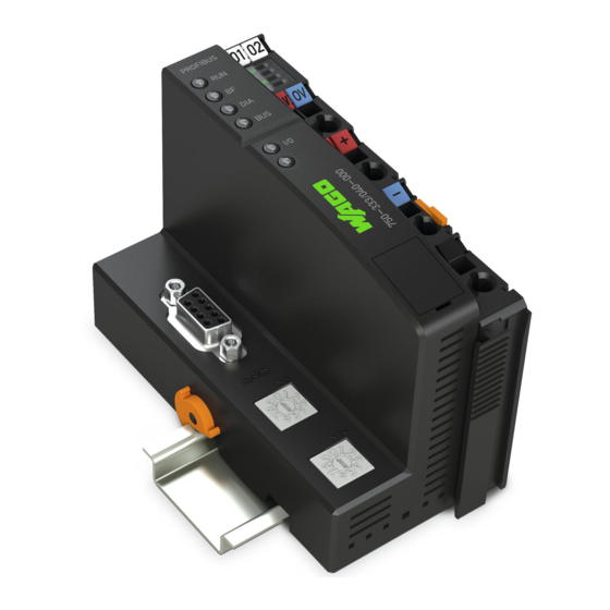
WAGO I/O SYSTEM 750 XTR Device Description 750-333/040-000 FC PROFIBUS G2 12MBd XTR View The view below shows the three parts of the device: • The fieldbus connection is on the left side. • LEDs for operation status, bus communication, error messages and diagnostics, as well as the service interface are in the middle area. -
Page 48: Table 13: Legend For Figure "View
Device Description WAGO I/O SYSTEM 750 XTR 750-333/040-000 FC PROFIBUS G2 12MBd XTR Table 13: Legend for Figure “View” Desig- Pos. Meaning Details see Section nation „Device Description“ > RUN, BF, Status LEDs Fieldbus „Display Elements“ DIA, BUS “Device Description” >... -
Page 49: Connectors
WAGO I/O SYSTEM 750 XTR Device Description 750-333/040-000 FC PROFIBUS G2 12MBd XTR Connectors 4.2.1 Device Supply ® The device is powered via terminal blocks with CAGE CLAMP connections. The device supply generates the necessary voltage to power the electronics of the device and the internal electronics of the connected I/O modules. -
Page 50: Fieldbus Connection
Device Description WAGO I/O SYSTEM 750 XTR 750-333/040-000 FC PROFIBUS G2 12MBd XTR 4.2.2 Fieldbus Connection Figure 26: Pin Assignment for D-Sub Fieldbus Connection (Female) The D-Sub connector for the RS-485 interface is wired as follows: Table 14: Signal Assignment of the RS-485 Interface... -
Page 51: Display Elements
WAGO I/O SYSTEM 750 XTR Device Description 750-333/040-000 FC PROFIBUS G2 12MBd XTR Display Elements The operating condition of the fieldbus coupler or the node is displayed with the help of illuminated indicators in the form of light-emitting diodes (LEDs). -
Page 52: Operating Elements
4.4.1 Service Interface The service interface is located behind the flap. It is used for the communication with the WAGO-I/O-CHECK and for downloading the firmware updates. Figure 28: Service Interface (Closed and Opened Flap) Table 18: Legend for Figure “Service Interface (Closed and Opened Flap)”... -
Page 53: Rotary Encoder Switch Station Address
WAGO I/O SYSTEM 750 XTR Device Description 750-333/040-000 FC PROFIBUS G2 12MBd XTR 4.4.2 Rotary Encoder Switch Station Address Two decimal rotary encoder switches on the fieldbus coupler/controller are used to set the station address. Figure 29: Rotary Encoder Switch Station Address The “x1”... -
Page 54: Technical Data
Device Description WAGO I/O SYSTEM 750 XTR 750-333/040-000 FC PROFIBUS G2 12MBd XTR Technical Data 4.5.1 Device Data Table 19: Technical Data – Device Width 51 mm Height (from upper edge of DIN-rail) 64 mm Depth 100 mm Weight 182 g... -
Page 55: Supply
WAGO I/O SYSTEM 750 XTR Device Description 750-333/040-000 FC PROFIBUS G2 12MBd XTR 4.5.3 Supply Table 21: Technical Data – Supply Internal current consumption (5 VDC) 200 mA Total current for I/O modules (5 VDC) 1800 mA Input current (24 VDC) 500 mA max. -
Page 56: Connection Type
Device Description WAGO I/O SYSTEM 750 XTR 750-333/040-000 FC PROFIBUS G2 12MBd XTR 4.5.5 Connection Type Table 23: Technical Data – Field Wiring ® Wire connection CAGE CLAMP 0.25 mm² … 2.5 mm² / AWG 24 … 14 Cross section 8 mm …... -
Page 57: Approvals
Approvals More information about approvals. Detailed references to the approvals are listed in the document “Overview Approvals WAGO I/O SYSTEM 750”, which you can find via the internet under: DOWNLOADS Documentation System Description. www.wago.com The following approvals have been granted to 750-333/040-000 fieldbus... - Page 58 Device Description WAGO I/O SYSTEM 750 XTR 750-333/040-000 FC PROFIBUS G2 12MBd XTR LR (Lloyd’s Register) Env. 1, 2, 3, 4 PRS (Polski Rejestr Statków) Manual Version 1.4.0...
-
Page 59: Standards And Guidelines
WAGO I/O SYSTEM 750 XTR Device Description 750-333/040-000 FC PROFIBUS G2 12MBd XTR Standards and Guidelines 750-333/040-000 fieldbus coupler/controller meets the following standards and guidelines: Table 28: Standards and Rated Conditions for Explosion Protection Applications ATEX acc. Directive 2014/34/EU General Requirements... -
Page 60: Table 29: Climatic And Mechanical Environmental Conditions And Shipbuilding
Device Description WAGO I/O SYSTEM 750 XTR 750-333/040-000 FC PROFIBUS G2 12MBd XTR Table 29: Climatic and Mechanical Environmental Conditions and Shipbuilding Standard Test Value Transport EN 60870-2-2 Ct2(2k4) (except precipitation/water/moisture) Mechanical Environmental Conditions EN 61850-3 Achieved EN 60870-2-2 EN 60721-3-1... -
Page 61: Table 30: Emc - Immunity To Interference
WAGO I/O SYSTEM 750 XTR Device Description 750-333/040-000 FC PROFIBUS G2 12MBd XTR The fieldbus coupler/controller 750-333/040-000 meets the following EMC standards as these standards relate to the fieldbus coupler/controller: Table 30: EMC – Immunity to Interference Standard Test Value Electrostatic Discharge •... - Page 62 Device Description WAGO I/O SYSTEM 750 XTR 750-333/040-000 FC PROFIBUS G2 12MBd XTR Table 30: EMC – Immunity to Interference Standard Test Value Line Frequency Disturbances • EN 60255-26 Standard not applicable Alternating Components of the Voltage to DC Line Connections •...
-
Page 63: Table 31: Emc - Emission Of Interference
WAGO I/O SYSTEM 750 XTR Device Description 750-333/040-000 FC PROFIBUS G2 12MBd XTR Table 31: EMC – Emission of Interference Standard Test Value Enclosure Emission of Interference • EN 61000-6-3 • EN 55032 Class B • EN 61000-6-4 40 dB(µV/m), QP, 30 MHz … 230 MHz •... -
Page 64: Table 32: Standards And Rated Conditions For Rail Applications (En 50155)
EN 50121-3-2 5.5 EMC (Emission of Interference, EN 50121-3-2 Immunity to Interference) EN 50121-4 EN 50121-5 9.11 Materials (Fire Protection) EN 45545-2 Hazard level HL3 WAGO is a company certified in accordance with the IRIS quality standard. Manual Version 1.4.0... -
Page 65: Mounting
WAGO I/O SYSTEM 750 XTR Mounting 750-333/040-000 FC PROFIBUS G2 12MBd XTR Mounting Installation Position The following mounting positions are approved for the WAGO I/O SYSTEM 750 XTR: • Nominal mounting position (horizontal left) • Floor mounting position • Vertical top mounting position •... -
Page 66: Figure 30: Mounting Positions
Mounting WAGO I/O SYSTEM 750 XTR 750-333/040-000 FC PROFIBUS G2 12MBd XTR Figure 30: Mounting Positions Use an end stop in the case of vertical installation! When mounting in the “vertical top” or “vertical bottom" mounting position, also mount an end stop below the fieldbus node to protect the fieldbus node against sliding. -
Page 67: Overall Configuration
WAGO I/O SYSTEM 750 XTR Mounting 750-333/040-000 FC PROFIBUS G2 12MBd XTR For vibration loads > 4g, observe the following installation instructions: • Use pan-head screws or blind rivets at least every 60 mm (12 mm pin spacing) to secure the DIN rail. -
Page 68: Mounting Onto Carrier Rail
WAGO Kontakttechnik GmbH & Co. KG supplies standardized carrier rails that are optimal for use with the I/O system. If other carrier rails are used, then a technical inspection and approval of the rail by WAGO Kontakttechnik GmbH & Co. KG should take place. -
Page 69: Wago Din Rails
WAGO I/O SYSTEM 750 XTR Mounting 750-333/040-000 FC PROFIBUS G2 12MBd XTR 5.3.2 WAGO DIN Rails WAGO carrier rails meet the electrical and mechanical requirements shown in the table below. Table 33: WAGO DIN Rails Item No. Description 210-112 35 × 7.5; 1 mm; steel; bluish, tinned, chromed; slotted 210-113 35 ×... -
Page 70: Spacing
Mounting WAGO I/O SYSTEM 750 XTR 750-333/040-000 FC PROFIBUS G2 12MBd XTR Spacing The spacing between adjacent components, cable conduits, casing and frame sides must be maintained for the complete fieldbus node. Figure 31: Spacing The spacing creates room for heat transfer, installation or wiring. The spacing to cable conduits also prevents conducted electromagnetic interferences from influencing the operation. -
Page 71: Mounting Sequence
Mounting 750-333/040-000 FC PROFIBUS G2 12MBd XTR Mounting Sequence Fieldbus couplers, controllers and I/O modules of the WAGO I/O SYSTEM 750 are snapped directly on a carrier rail in accordance with the European standard EN 60175 (DIN 35). The reliable positioning and connection is made using a tongue and groove system. -
Page 72: Inserting And Removing Devices
Mounting WAGO I/O SYSTEM 750 XTR 750-333/040-000 FC PROFIBUS G2 12MBd XTR Mixed operation Mixed operation (standard/XTR modules) within a node is possible when groups of modules are electrically isolated on the field side (i.e., electrically isolated power supply). Inserting and Removing Devices Do not work when devices are energized! High voltage can cause electric shock or burns. -
Page 73: Removing The Fieldbus Coupler/Controller
WAGO I/O SYSTEM 750 XTR Mounting 750-333/040-000 FC PROFIBUS G2 12MBd XTR 5.6.2 Removing the Fieldbus Coupler/Controller Use a screwdriver blade to turn the locking disc until the nose of the locking disc no longer engages behind the carrier rail. -
Page 74: Figure 34: Snap The I/O Module Into Place (Example)
Mounting WAGO I/O SYSTEM 750 XTR 750-333/040-000 FC PROFIBUS G2 12MBd XTR Press the I/O module into the assembly until the I/O module snaps into the carrier rail. Figure 34: Snap the I/O Module into Place (Example) With the I/O module snapped in place, the electrical connections for the data contacts and power jumper contacts (if any) to the fieldbus coupler/controller or to the previous or possibly subsequent I/O module are established. -
Page 75: Removing The I/O Module
WAGO I/O SYSTEM 750 XTR Mounting 750-333/040-000 FC PROFIBUS G2 12MBd XTR 5.6.4 Removing the I/O Module Remove the I/O module from the assembly by pulling the release tab. Figure 35: Removing the I/O Module (Example) Electrical connections for data or power jumper contacts are disconnected when removing the I/O module. -
Page 76: Connect Devices
Connect Devices WAGO I/O SYSTEM 750 XTR 750-333/040-000 FC PROFIBUS G2 12MBd XTR Connect Devices Data Contacts/Local Bus Communication between the fieldbus coupler/controller and the I/O modules as well as the system supply of the I/O modules is carried out via the local bus. The contacting for the local bus consists of 6 data contacts, which are available as self-cleaning gold spring contacts. -
Page 77: Power Contacts/Field Supply
WAGO I/O SYSTEM 750 XTR Connect Devices 750-333/040-000 FC PROFIBUS G2 12MBd XTR Power Contacts/Field Supply Risk of injury due to sharp-edged blade contacts! The blade contacts are sharp-edged. Handle the I/O module carefully to prevent injury. Do not touch the blade contacts. -
Page 78: Connecting A Conductor To The Cage Clamp
Only one conductor may be connected to each CAGE CLAMP Do not connect more than one conductor at one single connection! If more than one conductor must be routed to one connection, these must be connected in an up-circuit wiring assembly, for example using WAGO feed- through terminals. ®... -
Page 79: Function Description
WAGO I/O SYSTEM 750 XTR Function Description 750-333/040-000 FC PROFIBUS G2 12MBd XTR Function Description Operating System After master configuration and electrical installation of the fieldbus station, the system is operative. The fieldbus coupler begins running up after switching on the power supply or after a reset. -
Page 80: Process Data Architecture
Function Description WAGO I/O SYSTEM 750 XTR 750-333/040-000 FC PROFIBUS G2 12MBd XTR Process Data Architecture 7.2.1 Basic Structure A node can consist of a mixed arrangement of analog and digital, system and special function modules. For the configuration only I/O modules are taken into account, which exchange process data on the local bus with the fieldbus coupler (data width or bit width greater than 0). -
Page 81: Configuration Of Process Data For Profibus Dp
(D0 ... Dn) for the word and double-word-oriented modules are transmitted in a Motorola or Intel format via PROFIBUS. Additional Information: For the fieldbus-specific process image of any WAGO I/O module, please refer to the section “Appendix” > … > “Configurations of the Process Data …”. Manual... -
Page 82: Commissioning
Commissioning WAGO I/O SYSTEM 750 XTR 750-333/040-000 FC PROFIBUS G2 12MBd XTR Commissioning This section shows a step-by-step procedure for starting up exemplarily a WAGO fieldbus node. Planning The node is planned in accordance with the physical arrangement of fieldbus coupler/controller and I/O modules. -
Page 83: Gsd Files
WAGO I/O SYSTEM 750 XTR Commissioning 750-333/040-000 FC PROFIBUS G2 12MBd XTR GSD Files With PROFIBUS DP, the devices' power features are defined by the manufacturer in a GSD file (General Station Description or device master data file) and made available to the user. -
Page 84: Table 34: Identifier Bytes - Configuration Identifier In The General Identifier Format
Commissioning WAGO I/O SYSTEM 750 XTR 750-333/040-000 FC PROFIBUS G2 12MBd XTR Table 34: Identifier bytes – configuration identifier in the general identifier format Information Byte \ - - / \ - - / \ - - - - - - /... -
Page 85: Table 36: Identifier Bytes - Configuration Identifier In The Special Identifier Format (Length Byte)
WAGO I/O SYSTEM 750 XTR Commissioning 750-333/040-000 FC PROFIBUS G2 12MBd XTR Table 36: Identifier bytes – configuration identifier in the special identifier format (length byte) Information Byte Length byte(s) \ - - / \ - - / \ - - - - - - - - - - - - - - - - - - - - - - - - /... -
Page 86: Table 37: Identifier Bytes - Configuration Identifier In The Special Identifier Format (Datatype Byte)
Commissioning WAGO I/O SYSTEM 750 XTR 750-333/040-000 FC PROFIBUS G2 12MBd XTR Table 37: Identifier bytes – configuration identifier in the special identifier format (datatype byte) Information Byte Datatype byte(s) … 16/1 \ - - - - - - - - - - - - - - - - - - - - - - - - - - - - - - - - /... -
Page 87: Table 38: Table Modules
WAGO I/O SYSTEM 750 XTR Commissioning 750-333/040-000 FC PROFIBUS G2 12MBd XTR Table 38: Table Modules Module Description Example Module Identifier byte according to the general 75x-400 2 DI/24 V DC/3.0 ms identifier format for digital input or output I/O... -
Page 88: Table 39: Parameters - Settings
Commissioning WAGO I/O SYSTEM 750 XTR 750-333/040-000 FC PROFIBUS G2 12MBd XTR The arrangement and meaning of the module information in the process images depends on the following settings: • Process of the configuration check on the part of the station proxy Parameter Station proxy: “Start-up if expected and actual configuration... -
Page 89: Pi Configuration
WAGO I/O SYSTEM 750 XTR Commissioning 750-333/040-000 FC PROFIBUS G2 12MBd XTR PI Configuration 8.4.1 Application Example The physical configuration of the node is determined by: The configuration of the planned I/O modules with the DP fieldbus coupler, The slot properties in the respective module parameters and The “Startup if expected and actual configuration differ”... - Page 90 Commissioning WAGO I/O SYSTEM 750 XTR 750-333/040-000 FC PROFIBUS G2 12MBd XTR Table 40: Planned station configuration Slot Channel DP module Slot properties DP master module DP identification Pro- physical Module Diagnostics I-PI O-PI jec- is physi- is mapped (set-...
-
Page 91: Physical Station Design With Deactivated Parameter "Startup If Expected And Actual Configuration Differ
WAGO I/O SYSTEM 750 XTR Commissioning 750-333/040-000 FC PROFIBUS G2 12MBd XTR Physical station design with deactivated parameter “Startup if 8.4.1.1 expected and actual configuration differ” Figure 41: Physical station design with deactivated parameter “Startup if expected and actual configuration differ” (sample) If the parameter “Startup when expected/actual configuration differ”... -
Page 92: Physical Station Design With Activated Parameter "Startup If Expected And Actual Configuration Differ" 1
Commissioning WAGO I/O SYSTEM 750 XTR 750-333/040-000 FC PROFIBUS G2 12MBd XTR Physical station design with activated parameter “Startup if expected 8.4.1.2 and actual configuration differ” 1 Figure 42: Physical station design with activated parameter “Startup if expected and actual configuration differ”... -
Page 93: Configuration Differ" 2
WAGO I/O SYSTEM 750 XTR Commissioning 750-333/040-000 FC PROFIBUS G2 12MBd XTR Physical station design with activated parameter “Startup if expected 8.4.1.3 and actual configuration differ” 2 Figure 43: Physical station design with activated parameter “Startup if expected and actual configuration differ”... -
Page 94: Parameterization
Commissioning WAGO I/O SYSTEM 750 XTR 750-333/040-000 FC PROFIBUS G2 12MBd XTR Parameterization Before data can be exchanged between the DP master and DP slave, parameterization is required in addition to the configuration. The respective configuration tool of the DP master, e.g. SIMATIC HW Config, is... -
Page 95: Parameterization On Demand
WAGO I/O SYSTEM 750 XTR Commissioning 750-333/040-000 FC PROFIBUS G2 12MBd XTR 8.5.3 Parameterization on demand The DP/V0 parameter assignment message makes its specific parameter sets available before commencing cyclical active data exchange; this information is also provided to the fieldbus coupler and attached I/O modules. -
Page 96: Diagnostics
Diagnostics WAGO I/O SYSTEM 750 XTR 750-333/040-000 FC PROFIBUS G2 12MBd XTR Diagnostics LED Signaling For on-site diagnostics, the fieldbus coupler has several LEDs that indicate the operational status of the fieldbus coupler or the entire node (see following figure). -
Page 97: Evaluating The Fieldbus Status
WAGO I/O SYSTEM 750 XTR Diagnostics 750-333/040-000 FC PROFIBUS G2 12MBd XTR 9.1.1 Evaluating the Fieldbus Status The operating mode for communication via PROFIBUS is signaled by the four top LEDs, RUN, BF, DIA and BUS. Table 42: Diagnosis of Fieldbus Status – Solution in Event of Error... -
Page 98: Error Message Via Blink Code Of The Bus Led
Diagnostics WAGO I/O SYSTEM 750 XTR 750-333/040-000 FC PROFIBUS G2 12MBd XTR 9.1.2 Error Message via Blink Code of the BUS LED Table 43: Error message via blink code of the BUS LED Error argument Error description Remedy Error code 1: Error in parameterization telegram Insufficient parameterization data. -
Page 99: Evaluating Node Status - I/O Led (Blink Code Table)
WAGO I/O SYSTEM 750 XTR Diagnostics 750-333/040-000 FC PROFIBUS G2 12MBd XTR Evaluating Node Status – I/O LED (Blink Code Table) 9.1.3 The communication status between fieldbus coupler/controller and the I/O modules is indicated by the I/O LED. Table 44: Node Status Diagnostics – Solution in Event of Error... -
Page 100: Figure 45: Node Status - I/O Led Signaling
100 Diagnostics WAGO I/O SYSTEM 750 XTR 750-333/040-000 FC PROFIBUS G2 12MBd XTR Figure 45: Node Status – I/O LED Signaling Figure 46: Error Message Coding Example of a module error: • The I/O LED starts the error display with the first flashing sequence (approx. -
Page 101: Table 45: Blink Code Table For The I/O Led Signaling, Error Code 1
WAGO I/O SYSTEM 750 XTR Diagnostics 101 750-333/040-000 FC PROFIBUS G2 12MBd XTR Error argument 12 means that the local bus is interrupted behind the twelfth I/O module. The thirteenth I/O module is either defective or has been pulled out of the assembly. -
Page 102: Table 46: Blink Code Table For The I/O Led Signaling, Error Code 2
102 Diagnostics WAGO I/O SYSTEM 750 XTR 750-333/040-000 FC PROFIBUS G2 12MBd XTR Table 45: Blink Code Table for the I/O LED Signaling, Error Code 1 Error code 1: “Hardware and configuration error” Error Error Description Solution Argument Turn off the power supply for the node. -
Page 103: Table 47: Blink Code Table For The I/O Led Signaling, Error Code 3
WAGO I/O SYSTEM 750 XTR Diagnostics 103 750-333/040-000 FC PROFIBUS G2 12MBd XTR Table 47: Blink Code Table for the I/O LED Signaling, Error Code 3 Error code 3: “Protocol error, internal bus” Error Error Description Solution Argument - Are passive power supply modules (750-613) located in the... -
Page 104: Table 48: Blink Code Table For The I/O Led Signaling, Error Code 4
104 Diagnostics WAGO I/O SYSTEM 750 XTR 750-333/040-000 FC PROFIBUS G2 12MBd XTR Table 48: Blink Code Table for the I/O LED Signaling, Error Code 4 Error code 4: “Physical error, internal bus” Error Error Description Solution Argument Turn off the power supply to the node. -
Page 105: Table 50: Blink Code Table For The 'I/O' Led Signaling, Error Code 6
WAGO I/O SYSTEM 750 XTR Diagnostics 105 750-333/040-000 FC PROFIBUS G2 12MBd XTR Table 50: Blink Code Table for the 'I/O' LED Signaling, Error Code 6 Error code 6: -not used- Error Error Description Solution Argument Not used Table 51: Blink Code Table for the 'I/O' LED Signaling, Error Code 7 … 8 Error code 7 …... -
Page 106: Evaluating Power Supply Status
106 Diagnostics WAGO I/O SYSTEM 750 XTR 750-333/040-000 FC PROFIBUS G2 12MBd XTR 9.1.4 Evaluating Power Supply Status The power supply unit of the device has two green LEDs that indicate the status of the power supplies. LED 'A' indicates the 24 V supply of the coupler. -
Page 107: Local Bus Failure
WAGO I/O SYSTEM 750 XTR Diagnostics 107 750-333/040-000 FC PROFIBUS G2 12MBd XTR 9.2.2 Local Bus Failure 'I/O' LED indicates a local bus failure. 'I/O' LED flashes red: When a local bus failure occurs, the fieldbus coupler generates an error message (error code and error argument). -
Page 108: Table 57: Diagnostics
108 Diagnostics WAGO I/O SYSTEM 750 XTR 750-333/040-000 FC PROFIBUS G2 12MBd XTR Table 57: Diagnostics Designation Length in Additional information diagnostics frame PROFIBUS DP Station status 1 1 Byte See EN 61158 standard Station status 2 1 Byte See EN 61158... -
Page 109: Station Status 1 To 3
WAGO I/O SYSTEM 750 XTR Diagnostics 109 750-333/040-000 FC PROFIBUS G2 12MBd XTR 9.3.1 Station status 1 to 3 see IEC 61158 9.3.2 PROFIBUS DP Master Address The byte contains the station address of the class 1 master that parameterized and configured the fieldbus coupler, and thus has read and written access to the process data in the station. -
Page 110: Table 58: Identifier-Related Diagnostics - Structure
110 Diagnostics WAGO I/O SYSTEM 750 XTR 750-333/040-000 FC PROFIBUS G2 12MBd XTR Table 58: Identifier-related Diagnostics – Structure Byte- Information Meaning offset Header byte Identifier- Length of the identifier-related related diagnostics diagnostics incl. header (2-9 byte) Diagnostics slot 1-8... -
Page 111: Table 59: Identifier-Related Diagnostics - Example
WAGO I/O SYSTEM 750 XTR Diagnostics 111 750-333/040-000 FC PROFIBUS G2 12MBd XTR Table 59: Identifier-related Diagnostics – Example Byte Information Meaning offset Header byte (4-byte module-related diagnostics incl. header) Slot assignment: 1 (2 ): fieldbus coupler/-controller 2 … 64 (2 …2... -
Page 112: Device Status
112 Diagnostics WAGO I/O SYSTEM 750 XTR 750-333/040-000 FC PROFIBUS G2 12MBd XTR 9.3.5 Device Status The device status includes the required Overhead 7 byte and transmits device information about the internal status, local bus status or PROFIBUS DP status to the master or superior controller as required. -
Page 113: Internal Status Messages And Arguments
WAGO I/O SYSTEM 750 XTR Diagnostics 113 750-333/040-000 FC PROFIBUS G2 12MBd XTR 9.3.5.1 Internal status messages and arguments Table 61: Internal status messages and arguments Device status Description Message Argument 0x00 0x00 No fault 0x01 0x00 EEPROM checksum error / checksum error in parameter range of... -
Page 114: Module Status
114 Diagnostics WAGO I/O SYSTEM 750 XTR 750-333/040-000 FC PROFIBUS G2 12MBd XTR 9.3.6 Module Status The module status returns the status of the configured I/O modules on the respective slot. The fieldbus coupler/-controller can be populated with up to 63... -
Page 115: Channel-Specific Diagnostics
WAGO I/O SYSTEM 750 XTR Diagnostics 115 750-333/040-000 FC PROFIBUS G2 12MBd XTR 9.3.7 Channel-specific diagnostics The channel-specific diagnostics detail the identifier-related diagnostics or module status. For each faulty slot, one structure is added to the diagnostics frame per diagnosis. -
Page 116: Error Types Of I/O Modules With Diagnostics Capability
9.3.7.1 Error Types of I/O Modules with Diagnostics Capability The error numbers 0 to 9 refer to standardized error desriptions. The WAGO specific error are arranged from error number 17 and up. Table 66: Error types of I/O modules with diagnostics capability... -
Page 117: I/O Module Fault Cases
WAGO I/O SYSTEM 750 XTR Diagnostics 117 750-333/040-000 FC PROFIBUS G2 12MBd XTR 9.3.7.2 I/O Module Fault Cases Table 67: I/O module fault cases Item number Type of Error type Meaning channel 75x-418, 75x-419, '001 1.1010' External fault (broken wire, overload or... - Page 118 118 Diagnostics WAGO I/O SYSTEM 750 XTR 750-333/040-000 FC PROFIBUS G2 12MBd XTR Table 67: I/O module fault cases Item number Type of Error type Meaning channel 750-610, 750-611 '001 1.0001' Field voltage fault 1.0010' Fuse fault 75x-630 '110 0.1001' Error 1.0110'...
-
Page 119: Profisafe Parameterization Fault
WAGO I/O SYSTEM 750 XTR Diagnostics 119 750-333/040-000 FC PROFIBUS G2 12MBd XTR Table 68: Status messages Byte- Information Meaning off- Header byte Alarm or Length of the status message incl. status header Message type Sta- Status type = 1 (status message) -
Page 120: Wago-Specific Error Messages
120 Diagnostics WAGO I/O SYSTEM 750 XTR 750-333/040-000 FC PROFIBUS G2 12MBd XTR 9.3.8.1 WAGO-specific error messages Table 70: WAGO-specific error messages PROFIsafe Parameterization Fault Item number Fault number Meaning 75x-464, 75x-482, 16dez (0x0010) Parameterization fault 75x-484, 75x-562, 75x-563, 75x-644, 75x-652,... -
Page 121: Acyclic Communication According To Dp/V1
WAGO I/O SYSTEM 750 XTR Diagnostics 121 750-333/040-000 FC PROFIBUS G2 12MBd XTR Acyclic Communication according to DP/V1 In addition to cyclic data communication (PROFIBUS DP standard in compliance with IEC 61158), PROFIBUS DP also offers acyclic communication services as an option. -
Page 122: Data Areas
122 Diagnostics WAGO I/O SYSTEM 750 XTR 750-333/040-000 FC PROFIBUS G2 12MBd XTR MSAC1 connection is closed when the DP data exchange is left. In the event of cyclic or acyclic connection failures, both communication channels will be closed. The MSAC2_Initiate service is used to open an acyclic MSAC2 connection. Once the connection has been established, it will be monitored by the C2 master. -
Page 123: Fieldbus Coupler, Slots 0 And 1
WAGO I/O SYSTEM 750 XTR Diagnostics 123 750-333/040-000 FC PROFIBUS G2 12MBd XTR 9.4.1.1 Fieldbus coupler, slots 0 and 1 Table 73: Fieldbus coupler, slots 0 and 1 Index Meaning Service primitives / Data length [Byte] ... 07 Reserved for expansions MSAC1/2_Read / 2 …... -
Page 124: Digital I/O Modules, Slots 2
124 Diagnostics WAGO I/O SYSTEM 750 XTR 750-333/040-000 FC PROFIBUS G2 12MBd XTR Table 75: Complex 8-Channel I/O Modules, Slots 2 … 64 Index Meaning 'xxx0.0000' Table register 0 … … 'xxx1.1010' Table register 26 'xxx1.1011' All table registers 'xxx1.1100' Diagnostics data of the channel 'xxx1.1101'... - Page 125 WAGO I/O SYSTEM 750 XTR Diagnostics 125 750-333/040-000 FC PROFIBUS G2 12MBd XTR Examples: • Accessing indices of an I/O module that is not physically connected. • Accessing the data areas of the third channel while using a 2-channel I/O module.
-
Page 126: Figure 47: Coding Error Messages
126 Diagnostics WAGO I/O SYSTEM 750 XTR 750-333/040-000 FC PROFIBUS G2 12MBd XTR Coding Error Messages Figure 47: Coding Error Messages Table 77: Meaning of the Octet 2 Error Messages Octet 2 Error Meaning Decode 0 ... 127 Reserved PROFIBUS DP/V1 129 ... -
Page 127: Table 78: Meaning Of The Octet 3 Error Messages
WAGO I/O SYSTEM 750 XTR Diagnostics 127 750-333/040-000 FC PROFIBUS G2 12MBd XTR Table 78: Meaning of the Octet 3 Error Messages Oktet 3 Error_Class Meaning Error_Code_1 Meaning 0 … 9 Reserved Application errors Read error Write error Module failure 3 …... -
Page 128: Fieldbus Communication
128 Fieldbus Communication WAGO I/O SYSTEM 750 XTR 750-333/040-000 FC PROFIBUS G2 12MBd XTR Fieldbus Communication PROFIBUS (Process Field Bus) was developed as an open fieldbus. It was standardized in DIN 19245 and then later merged into the International standard IEC 61158. -
Page 129: Cabling
100 m The 750-960, 750-970 fieldbus connectors offered by WAGO make it possible to connect the coming and going data cable to the connector directly. In this way, branch lines are avoided and the bus connector can plug in and unplug at without having to interrupt data traffic to the bus. -
Page 130: Figure 48: Bus Connection
130 Fieldbus Communication WAGO I/O SYSTEM 750 XTR 750-333/040-000 FC PROFIBUS G2 12MBd XTR Figure 48: Bus Connection Install bus connection When connecting the nodes, make sure that the data lines are not reversed. The bus connection at the start and end of the bus line must be installed. The bus connection needs the supply voltage VP from the device. - Page 131 WAGO I/O SYSTEM 750 XTR Fieldbus Communication 131 750-333/040-000 FC PROFIBUS G2 12MBd XTR Shield Connecting System WAGO offers the shield connecting system for optimal connection between fieldbus cable shielding and functional ground. Manual Version 1.4.0...
-
Page 132: O Modules
132 I/O Modules WAGO I/O SYSTEM 750 XTR 750-333/040-000 FC PROFIBUS G2 12MBd XTR I/O Modules 11.1 Overview For modular applications with the WAGO I/O SYSTEM 750, different types of I/O modules are available • Digital Input Modules • Digital Output Modules •... -
Page 133: Appendix
WAGO I/O SYSTEM 750 XTR Appendix 133 750-333/040-000 FC PROFIBUS G2 12MBd XTR Appendix 12.1 Configuration Identifiers 12.1.1 Fieldbus Coupler Table 82: Configuration Identifiers Fieldbus Coupler Order No. Description Module 750-333 No PI Channel 0x00 750-333 2 Byte PI Channel 0xB1 12.1.2... - Page 134 134 Appendix WAGO I/O SYSTEM 750 XTR 750-333/040-000 FC PROFIBUS G2 12MBd XTR Table 83: Configuration Identifiers Digital Input Modules Order No. Description Module *-Module 75x-431 8DI/24V DC/0.2ms 0x10 75x-432 4DI/24V DC/3.0ms 0x10 0x00 75x-433 4DI/24V DC/0.2ms 0x10 0x00 75x-434 8DI/5(12)V DC/0.2ms...
-
Page 135: Digital Output Modules
WAGO I/O SYSTEM 750 XTR Appendix 135 750-333/040-000 FC PROFIBUS G2 12MBd XTR 12.1.3 Digital Output Modules Table 84: Configuration Identifiers Digital Output Modules Order No. Description Module *-Module 75x-501 2DO/24V DC/0.5A 0x20 0x00 75x-502 2DO/24V DC/2.0A 0x20 0x00 75x-504 4DO/24V DC/0.5A... -
Page 136: Power Supply Modules
136 Appendix WAGO I/O SYSTEM 750 XTR 750-333/040-000 FC PROFIBUS G2 12MBd XTR Table 84: Configuration Identifiers Digital Output Modules Order No. Description Module *-Module 75x-5dd 0x20 0x00 75x-5dd 2DO/2DIA-DI/DIA 0x30 0x00 75x-5dd 2DO/2DIA 0x20 0x00 75x-5dd 2DO/4DIA-DI/DIA 0x30 0x00... -
Page 137: Analog Input Modules
WAGO I/O SYSTEM 750 XTR Appendix 137 750-333/040-000 FC PROFIBUS G2 12MBd XTR 12.1.5 Analog Input Modules Table 86: Configuration Identifiers Analog Input Modules Order No. Description Module RA-Module 750-450 4AI/RTD 0x53 0xF5 750-451 8AI/RTD 0x57 0xFB 750-452 2AI/0-20mA/diff. 0x51... -
Page 138: Analog Output Modules
138 Appendix WAGO I/O SYSTEM 750 XTR 750-333/040-000 FC PROFIBUS G2 12MBd XTR Table 86: Configuration Identifiers Analog Input Modules Order No. Description Module RA-Module 750-484 2AI/4-20mA/Ex i 3x2 HV 0x44, 0x9B, 0x03, 0x27, 0x03, 0x27 750-484 2AI/4-20mA/Ex i 4x2 HV... -
Page 139: Special Modules
WAGO I/O SYSTEM 750 XTR Appendix 139 750-333/040-000 FC PROFIBUS G2 12MBd XTR 12.1.7 Special Modules Table 88: Configuration Identifiers Special Modules Order No Description Module RA-Module 75x-404 U/D-Counter 0xF2 75x-511 2 DO/24 V DC/PWM 0xF2 75x-630 SSI-Interface 0x93 0xF2... - Page 140 140 Appendix WAGO I/O SYSTEM 750 XTR 750-333/040-000 FC PROFIBUS G2 12MBd XTR Table 88: Configuration Identifiers Special Modules Order No Description Module RA-Module 75x-666 4FDI/2FDO 24V/10A DC 0xC4, 0x84, 0x84, 0x05, 4FDI/2FDO iPar-Server 0x6E, 0x05, 0x6E 75x-667 4FDI/4FDO 24V/2.0A DC...
-
Page 141: Configuration Of The Process Data For Profibus Dp
The configuration of the process data is fieldbus specific at some I/O modules and their variations. The following section describes the representation for WAGO I/O SYSTEM 750 and 753 Series I/O modules in the process image of PROFIBUS DP, as well as the configuration of the process values. -
Page 142: Digital Input Modules
142 Appendix WAGO I/O SYSTEM 750 XTR 750-333/040-000 FC PROFIBUS G2 12MBd XTR 12.2.2 Digital Input Modules The PI configurations of the digital input modules are divided into the following module types: Table 91: Digital Input Modules – Module Types... -
Page 143: Table 92: Digital Input Modules - Number Of Bits And Bytes
WAGO I/O SYSTEM 750 XTR Appendix 143 750-333/040-000 FC PROFIBUS G2 12MBd XTR Table 92: Digital Input Modules – Number of Bits and Bytes I/O Modules Proxy * Proxy (PBDP module type) (PBDP module type) Data length Configuration Data length... -
Page 144: Table 93: Digital Input Modules - Process Image Information
144 Appendix WAGO I/O SYSTEM 750 XTR 750-333/040-000 FC PROFIBUS G2 12MBd XTR The following table describes the process image information of the individual module types for digital input modules. Table 93: Digital Input Modules – Process Image Information Bit/byte allocation... - Page 145 WAGO I/O SYSTEM 750 XTR Appendix 145 750-333/040-000 FC PROFIBUS G2 12MBd XTR Table 93: Digital Input Modules – Process Image Information Bit/byte allocation Offset PBDP module type [Byte] 8DI_8DIA_8DIA_DIS 8DI_8PI-DIA_8DIA_ 8DI_8DIA_8DI_DIS 8DI_8PI-DIA_8DI_DIS 16DI Bit position reserved with the binary information of a digital input channel.
-
Page 146: Digital Output Modules
146 Appendix WAGO I/O SYSTEM 750 XTR 750-333/040-000 FC PROFIBUS G2 12MBd XTR 12.2.3 Digital Output Modules The PI configurations of the digital output modules are divided into the following module types: Table 94: Digital Output Modules – Module Types... -
Page 147: Table 95: Digital Output Modules - Number Of Bits And Bytes
WAGO I/O SYSTEM 750 XTR Appendix 147 750-333/040-000 FC PROFIBUS G2 12MBd XTR Table 95: Digital Output Modules – Number of Bits and Bytes I/O Modules Proxy *Proxy (PBDP module type) (PBDP module type) Data length Configuration Data length Configuration... -
Page 148: Table 96: Digital Output Modules - Process Image Information
148 Appendix WAGO I/O SYSTEM 750 XTR 750-333/040-000 FC PROFIBUS G2 12MBd XTR The following table describes the process image information of the individual module types for digital output modules. Table 96: Digital Output Modules – Process Image Information Bit/byte allocation... - Page 149 WAGO I/O SYSTEM 750 XTR Appendix 149 750-333/040-000 FC PROFIBUS G2 12MBd XTR Table 96: Digital Output Modules – Process Image Information Bit/byte allocation Offset PBDP module type [Byte] 4DO_4DIA *4DO_4DIA 4DO_4PI-DIA *4DO_4PI-DIA 8DO_8DIA 8DO_8PI-DIA 16DO Bit position reserved with the binary information of a digital input channel.
-
Page 150: Digital Input/Output Modules
150 Appendix WAGO I/O SYSTEM 750 XTR 750-333/040-000 FC PROFIBUS G2 12MBd XTR 12.2.4 Digital Input/Output Modules For the PI configuration for the digital input/digital output modules, there is one module type available: Table 97: Digital Input/Output Modules – Module Types... -
Page 151: Analog Input Modules
WAGO I/O SYSTEM 750 XTR Appendix 151 750-333/040-000 FC PROFIBUS G2 12MBd XTR 12.2.5 Analog Input Modules The PI configurations of the analog input modules are divided into the following module types: Table 100: Analog Input Modules – Module Types... -
Page 152: Table 101: Analog Input Modules - Number Of Bytes
152 Appendix WAGO I/O SYSTEM 750 XTR 750-333/040-000 FC PROFIBUS G2 12MBd XTR Table 101: Analog Input Modules – Number of Bytes Proxy (PBDP module type) I/O Modules Data length Configuration identifier Data type Inst. [Byte] PBDP module type 2AI(_PAR) - Page 153 WAGO I/O SYSTEM 750 XTR Appendix 153 750-333/040-000 FC PROFIBUS G2 12MBd XTR Table 102: Analog Input Modules – Process Image Information Bit/byte allocation Offset PBDP module type [Byte] 2AI_2HV Input data Channel 0, HB Input data Channel 0, LB...
- Page 154 154 Appendix WAGO I/O SYSTEM 750 XTR 750-333/040-000 FC PROFIBUS G2 12MBd XTR Table 102: Analog Input Modules – Process Image Information Bit/byte allocation Offset PBDP module type [Byte] 2AI_6HV Input data Channel 0, HB Input data Channel 0, LB...
- Page 155 WAGO I/O SYSTEM 750 XTR Appendix 155 750-333/040-000 FC PROFIBUS G2 12MBd XTR Table 102: Analog Input Modules – Process Image Information Bit/byte allocation Offset PBDP module type [Byte] 2AI_8HV Input data Channel 0, HB Input data channel 0 Secondary variable 1...
-
Page 156: Table 102: Analog Input Modules - Process Image Information
156 Appendix WAGO I/O SYSTEM 750 XTR 750-333/040-000 FC PROFIBUS G2 12MBd XTR Table 102: Analog Input Modules – Process Image Information Bit/byte allocation Offset PBDP module type [Byte] Secondary variable 4 Channel 1, Byte 2 (Byte 1 Secondary variable 4... - Page 157 WAGO I/O SYSTEM 750 XTR Appendix 157 750-333/040-000 FC PROFIBUS G2 12MBd XTR Table 102: Analog Input Modules – Process Image Information Bit/byte allocation Offset PBDP module type [Byte] 4AI(_PAR) Input data Channel 0, HB Input data Channel 0, LB...
- Page 158 158 Appendix WAGO I/O SYSTEM 750 XTR 750-333/040-000 FC PROFIBUS G2 12MBd XTR Table 102: Analog Input Modules – Process Image Information Bit/byte allocation Offset PBDP module type [Byte] 4AI_RA(_PAR) Status 0 / Register RES Channel 0 / Table 0...
- Page 159 WAGO I/O SYSTEM 750 XTR Appendix 159 750-333/040-000 FC PROFIBUS G2 12MBd XTR Table 102: Analog Input Modules – Process Image Information Bit/byte allocation Offset PBDP module type [Byte] 8AI_PAR Input data Channel 0, HB Input data Channel 0, LB...
- Page 160 160 Appendix WAGO I/O SYSTEM 750 XTR 750-333/040-000 FC PROFIBUS G2 12MBd XTR Table 102: Analog Input Modules – Process Image Information Bit/byte allocation Offset PBDP module type [Byte] 8AI_RA_PAR Status 0 / Register RES Channel 0 / Table 0...
- Page 161 WAGO I/O SYSTEM 750 XTR Appendix 161 750-333/040-000 FC PROFIBUS G2 12MBd XTR Table 102: Analog Input Modules – Process Image Information Bit/byte allocation Offset PBDP module type [Byte] Control 3 / Register REQ Channel 3 / Table 3 Register data WR...
- Page 162 162 Appendix WAGO I/O SYSTEM 750 XTR 750-333/040-000 FC PROFIBUS G2 12MBd XTR Table 102: Analog Input Modules – Process Image Information Bit/byte allocation Offset PBDP module type [Byte] 3PLM_PAR Statuswort 0 / Register RES Channel 0 / Table 0...
- Page 163 WAGO I/O SYSTEM 750 XTR Appendix 163 750-333/040-000 FC PROFIBUS G2 12MBd XTR Table 102: Analog Input Modules – Process Image Information Bit/byte allocation Offset PBDP module type [Byte] Format MOTOROLA Format INTEL Manual Version 1.4.0...
-
Page 164: Analog Output Modules
164 Appendix WAGO I/O SYSTEM 750 XTR 750-333/040-000 FC PROFIBUS G2 12MBd XTR 12.2.6 Analog Output Modules The PI configurations of the analog output modules are divided into the following module types: Table 103: Analog Output Modules – Module Types... -
Page 165: Table 105: Analog Output Modules - Process Image Information
WAGO I/O SYSTEM 750 XTR Appendix 165 750-333/040-000 FC PROFIBUS G2 12MBd XTR Table 105: Analog Output Modules – Process Image Information Bit/byte allocation Offset PBDP module type [Byte] 2AO(_PAR) Output data Channel 0, HB Output data Channel 0, LB... - Page 166 166 Appendix WAGO I/O SYSTEM 750 XTR 750-333/040-000 FC PROFIBUS G2 12MBd XTR Table 105: Analog Output Modules – Process Image Information Bit/byte allocation Offset PBDP module type [Byte] 4AO_RA Status 0 / Register RES Channel 0 / Table 0...
-
Page 167: Up/Down Counters
WAGO I/O SYSTEM 750 XTR Appendix 167 750-333/040-000 FC PROFIBUS G2 12MBd XTR 12.2.7 Up/Down Counters The PI configurations of the up/down counters are divided into the following module types: Table 106: Up/down Counters – Module Types PBDP module type... - Page 168 168 Appendix WAGO I/O SYSTEM 750 XTR 750-333/040-000 FC PROFIBUS G2 12MBd XTR Table 108: Up/down Counters – Process Image Information Bit/byte allocation Offset PBDP module type [Byte] 2CNT Status 0 / Register RES Channel 0 / Table 0 Counter value 0...
-
Page 169: 2-Channel Pulse Width Output Module
WAGO I/O SYSTEM 750 XTR Appendix 169 750-333/040-000 FC PROFIBUS G2 12MBd XTR 12.2.8 2-Channel Pulse Width Output Module For the PI configuration for the 2-channel pulse width output module, there is one module type available: Table 109: 2-Channel Pulse Width Output Module – Module Types... -
Page 170: Table 112: Modules For Path And Angle Measurement - Module Types
170 Appendix WAGO I/O SYSTEM 750 XTR 750-333/040-000 FC PROFIBUS G2 12MBd XTR Table 112: Modules for Path and Angle Measurement – Module Types PBDP module type Description Proxy I/O modules SSI Encoder Interface, channel diagnostics, 75x-630 32 bit input data... -
Page 171: Table 114: Modules For Path And Angle Measurement
WAGO I/O SYSTEM 750 XTR Appendix 171 750-333/040-000 FC PROFIBUS G2 12MBd XTR Table 114: Modules for Path and Angle Measurement – Process Image Information Bit/byte allocation Offset PBDP module type [Byte] Input data Byte 3 (Byte 0 Input data... - Page 172 172 Appendix WAGO I/O SYSTEM 750 XTR 750-333/040-000 FC PROFIBUS G2 12MBd XTR Table 114: Modules for Path and Angle Measurement – Process Image Information Bit/byte allocation Offset PBDP module type [Byte] ENC_RA Status 0 / Register RES Channel 0 / Table 0...
-
Page 173: 12.2.10 Serial Interfaces
WAGO I/O SYSTEM 750 XTR Appendix 173 750-333/040-000 FC PROFIBUS G2 12MBd XTR 12.2.10 Serial Interfaces The PI configurations of the serial interfaces are divided into the following module types: Table 115: Serial Interfaces – Module Types PBDP module type... -
Page 174: Table 117: Serial Interfaces - Process Image Information
174 Appendix WAGO I/O SYSTEM 750 XTR 750-333/040-000 FC PROFIBUS G2 12MBd XTR Table 117: Serial Interfaces – Process Image Information Bit/byte allocation Offset PBDP module type [Byte] SER_3D Status 0 / Register RES Channel 0 / Table 0 Receive data... - Page 175 WAGO I/O SYSTEM 750 XTR Appendix 175 750-333/040-000 FC PROFIBUS G2 12MBd XTR Table 117: Serial Interfaces – Process Image Information Bit/byte allocation Offset PBDP module type [Byte] SER_6D_PAR Status 0 / Register RES Channel 0 / Table 0 Register data RD...
- Page 176 176 Appendix WAGO I/O SYSTEM 750 XTR 750-333/040-000 FC PROFIBUS G2 12MBd XTR Table 117: Serial Interfaces – Process Image Information Bit/byte allocation Offset PBDP module type [Byte] SER_46D_PAR Status 0 / Register RES Channel 0 / Table 0 Register data RD...
- Page 177 WAGO I/O SYSTEM 750 XTR Appendix 177 750-333/040-000 FC PROFIBUS G2 12MBd XTR Table 117: Serial Interfaces – Process Image Information Bit/byte allocation Offset PBDP module type [Byte] DXCH_RA Status 0 / Register RES Channel 0 / Table 0 Receive data...
-
Page 178: 12.2.11 Dali/Dsi Master Module
178 Appendix WAGO I/O SYSTEM 750 XTR 750-333/040-000 FC PROFIBUS G2 12MBd XTR 12.2.11 DALI/DSI Master Module For the PI configuration for the DALI/DSI modules, there is one module type available: Table 118: DALI/DSI Master Module – Module Types PBDP module type... -
Page 179: 12.2.12 As Interface Master
WAGO I/O SYSTEM 750 XTR Appendix 179 750-333/040-000 FC PROFIBUS G2 12MBd XTR 12.2.12 AS Interface Master The PI configurations of the AS interface master are divided into the following module types: Table 121: AS Interface Master – Module Types... -
Page 180: Table 123: As Interface Master - Process Image Information
180 Appendix WAGO I/O SYSTEM 750 XTR 750-333/040-000 FC PROFIBUS G2 12MBd XTR The following table describes the process image information, e.g., allocation of configuration modules, for the AS interface master module. All other possible process image assignments are available in the AS interface master module manual. - Page 181 WAGO I/O SYSTEM 750 XTR Appendix 181 750-333/040-000 FC PROFIBUS G2 12MBd XTR Table 123: AS Interface Master – Process Image Information Bit/byte allocation Offset PBDP module type [Byte] ASI_10D Control 0 / Register REQ Channel 0 / Table 0...
-
Page 182: 12.2.13 Radio Receiver I/O Modules
182 Appendix WAGO I/O SYSTEM 750 XTR 750-333/040-000 FC PROFIBUS G2 12MBd XTR 12.2.13 Radio Receiver I/O Modules The PI configurations of the radio receiver I/O modules are divided into the following module types: Table 124: Radio Receiver I/O Modules – Module Types... -
Page 183: Table 126: Radio Receiver I/O Modules - Process Image Information
WAGO I/O SYSTEM 750 XTR Appendix 183 750-333/040-000 FC PROFIBUS G2 12MBd XTR Table 126: Radio Receiver I/O Modules – Process Image Information Bit/byte allocation Offset PBDP module type [Byte] ENOC Status 0 / Register RES Channel 0 / Table 0... - Page 184 184 Appendix WAGO I/O SYSTEM 750 XTR 750-333/040-000 FC PROFIBUS G2 12MBd XTR Table 126: Radio Receiver I/O Modules – Process Image Information Bit/byte allocation Offset PBDP module type [Byte] BT_10D Control 0 / Register REQ Channel 0 / Table 0...
-
Page 185: 12.2.14 Mp Bus Master Module
WAGO I/O SYSTEM 750 XTR Appendix 185 750-333/040-000 FC PROFIBUS G2 12MBd XTR 12.2.14 MP Bus Master Module For the PI configuration for the MP bus modules, there is one module type available: Table 127: MP Bus Master Module – Module Types... -
Page 186: Table 129: Mp Bus Master Module - Process Image Information
186 Appendix WAGO I/O SYSTEM 750 XTR 750-333/040-000 FC PROFIBUS G2 12MBd XTR Table 129: MP Bus Master Module – Process Image Information Bit/byte allocation Offset PBDP module type [Byte] MP_Bus Status 0 / Register RES Channel 0 / Table 0... -
Page 187: 2-Channel Vibration Velocity/Bearing Condition Monitoring Vib I/O
WAGO I/O SYSTEM 750 XTR Appendix 187 750-333/040-000 FC PROFIBUS G2 12MBd XTR 12.2.15 2-Channel Vibration Velocity/Bearing Condition Monitoring VIB I/O For the PI configuration for the 2-Channel Vibration Velocity/Bearing Condition Monitoring VIB I/O, there is one module type available: Table 130: 2-Channel Vibration Velocity/Bearing Condition Monitoring VIB I/O –... -
Page 188: Table 132: Vibration Monitoring - Process Image Information
188 Appendix WAGO I/O SYSTEM 750 XTR 750-333/040-000 FC PROFIBUS G2 12MBd XTR Table 132: Vibration Monitoring – Process Image Information Bit/byte allocation Offset PBDP module type [Byte] VIB_IO Status 0 / Register RES Channel 0 / Table 0 RMS Vibration severity... -
Page 189: 12.2.16 Profisafe Modules
WAGO I/O SYSTEM 750 XTR Appendix 189 750-333/040-000 FC PROFIBUS G2 12MBd XTR 12.2.16 PROFIsafe Modules The PI configurations of the PROFIsafe modules are divided into the following module types: Table 133: PROFIsafe modules – Module types PBDP module type... -
Page 190: Table 135: Profisafe Modules - Process Image Information
190 Appendix WAGO I/O SYSTEM 750 XTR 750-333/040-000 FC PROFIBUS G2 12MBd XTR The following table describes the process image information of the individual module types for the PROFIsafe modules. Table 135: PROFIsafe modules – Process image information Bit/byte allocation... -
Page 191: 12.2.17 Rtc Module
WAGO I/O SYSTEM 750 XTR Appendix 191 750-333/040-000 FC PROFIBUS G2 12MBd XTR 12.2.17 RTC Module For the PI configuration for the RTC module, there is one module type available: Table 136: RTC Module – Module Types PBDP module type... -
Page 192: 12.2.18 Stepper Module
192 Appendix WAGO I/O SYSTEM 750 XTR 750-333/040-000 FC PROFIBUS G2 12MBd XTR 12.2.18 Stepper Module For the PI configuration for the stepper module, there is one module type available: Table 139: Stepper Module – Module Types PBDP module type... -
Page 193: Table 141: Stepper Module - Process Image Information
WAGO I/O SYSTEM 750 XTR Appendix 193 750-333/040-000 FC PROFIBUS G2 12MBd XTR Table 141: Stepper Module – Process Image Information Bit/byte allocation Offset PBDP module type [Byte] STEPPER Status 0 / Register RES Channel 0 / Table 0 Input data... -
Page 194: 12.2.19 Dc Drive Controller
194 Appendix WAGO I/O SYSTEM 750 XTR 750-333/040-000 FC PROFIBUS G2 12MBd XTR 12.2.19 DC Drive Controller The PI configurations of the DC drive controller are divided into the following module types: Table 142: DC Drive Controller – Module Types... -
Page 195: 12.2.20 Io-Link Master
WAGO I/O SYSTEM 750 XTR Appendix 195 750-333/040-000 FC PROFIBUS G2 12MBd XTR 12.2.20 IO-Link Master The PI configurations of the IO-Link master are divided into the following module types: Table 145: IO-Link Master – Module Types PBDP module type... -
Page 196: Table 147: Io-Link Master - Process Image Information
196 Appendix WAGO I/O SYSTEM 750 XTR 750-333/040-000 FC PROFIBUS G2 12MBd XTR The following table describes the process image information of the individual module types for the IO-Link master. Table 147: IO-Link Master – Process Image Information Bit/byte allocation... - Page 197 WAGO I/O SYSTEM 750 XTR Appendix 197 750-333/040-000 FC PROFIBUS G2 12MBd XTR Table 147: IO-Link Master – Process Image Information Bit/byte allocation Offset PBDP module type [Byte] IOL_SIO IOL_SIO_02D Output data Byte 0 Output data Byte 1 IOL_SIO_04D Output data Byte 2...
-
Page 198: 12.2.21 Supply Module With Diagnostics
198 Appendix WAGO I/O SYSTEM 750 XTR 750-333/040-000 FC PROFIBUS G2 12MBd XTR 12.2.21 Supply Module with Diagnostics The PI configurations of the supply module with diagnostics is divided into two module types: Table 148: Supply Modules with Diagnostics – Module Types... -
Page 199: Parameter Of The Fieldbus Coupler And The I/O Modules
WAGO I/O SYSTEM 750 XTR Appendix 199 750-333/040-000 FC PROFIBUS G2 12MBd XTR 12.3 Parameter of the Fieldbus Coupler and the I/O modules 12.3.1 Parameter of the Fieldbus Coupler 12.3.1.1 Parameters of the Station Proxy Table 151: Parameters of the fieldbus coupler as station proxy (FC_SSV) - Page 200 200 Appendix WAGO I/O SYSTEM 750 XTR 750-333/040-000 FC PROFIBUS G2 12MBd XTR Table 151: Parameters of the fieldbus coupler as station proxy (FC_SSV) FC_SSV (slot 0) 750-333 Parameterization data length in bytes Standard parameterization Structured parameterization Parameter Settings Description Scope •...
-
Page 201: Parameters Of The Process Data Channel
WAGO I/O SYSTEM 750 XTR Appendix 201 750-333/040-000 FC PROFIBUS G2 12MBd XTR 12.3.1.2 Parameters of the Process Data Channel Table 152: Parameters of the process data channel of the fieldbus coupler (FC_PZK) FC_PZK (slot 1) 750-333 Parameterization data length in bytes... -
Page 202: Parameters Of The I/O Modules
202 Appendix WAGO I/O SYSTEM 750 XTR 750-333/040-000 FC PROFIBUS G2 12MBd XTR 12.3.2 Parameters of the I/O Modules 12.3.2.1 Parameters of the Digital Input Modules The table shows the parameterization properties of the 1, 2, 4, 8 and 16-channel digital input modules without asynchronous diagnostic properties. -
Page 203: Table 155: Parameters Of The 2, 4, 8 And 16-Channel Digital Output Modules (Do)
WAGO I/O SYSTEM 750 XTR Appendix 203 750-333/040-000 FC PROFIBUS G2 12MBd XTR Table 155: Parameters of the 2, 4, 8 and 16-channel digital output modules (DO) 2DO, 4DO, 8DO, 16DO Representatives of the 2DO: 75x-501, 75x-502, 75x-509,´75x-512, 75x-513, Parameterization data length in bytes... -
Page 204: Parameters Of The Digital Input/Output Modules
204 Appendix WAGO I/O SYSTEM 750 XTR 750-333/040-000 FC PROFIBUS G2 12MBd XTR Table 156: Parameters of the 1, 2, 4 and 8-channel digital output modules (DO_DIA) 1DO_1DIA, 1DO_1PI-DIA, Representatives of the 1DO_1DIA or 1DO_1PI-DIA: 2DO_2DIA, 2DO_2PI-DIA, 75x-523, 2DO_4DIA, 2DO_4PI-DIA,... -
Page 205: Parameters Of The Analog Input Modules
WAGO I/O SYSTEM 750 XTR Appendix 205 750-333/040-000 FC PROFIBUS G2 12MBd XTR 12.3.2.4 Parameters of the Analog Input Modules The table shows the parameterization properties of the 1, 2, 3 and 4-channel analog input modules with asynchronous diagnostic properties, but without individual parameters. -
Page 206: Table 159: Parameters Of The 4(2)-Channel Analog Input Modules (Ai_Par)
206 Appendix WAGO I/O SYSTEM 750 XTR 750-333/040-000 FC PROFIBUS G2 12MBd XTR The table shows the parameterization properties of the 4 and 2-channel analog input modules with asynchronous diagnostic properties and individual parameters. Table 159: Parameters of the 4(2)-channel analog input modules (AI_PAR) -
Page 207: Table 160: Parameters Of The 2-Channel Analog Input Modules Hart (Ai_Hart)
WAGO I/O SYSTEM 750 XTR Appendix 207 750-333/040-000 FC PROFIBUS G2 12MBd XTR The table shows the parameterization properties of the 2-channel analog input modules HART with asynchronous diagnostic properties and individual parameters. Table 160: Parameters of the 2-channel analog input modules HART (AI_HART) -
Page 208: Table 161: Parameters Of The 4 (8)-Channel Analog Input Modules (Ai_Par)
208 Appendix WAGO I/O SYSTEM 750 XTR 750-333/040-000 FC PROFIBUS G2 12MBd XTR The table shows the parameterization properties of the 4 and 8-channel analog input modules with asynchronous diagnostic properties and individual parameters. Table 161: Parameters of the 4 (8)-channel analog input modules (AI_PAR) -
Page 209: Table 162: Parameter Of The 3-Phase Power Measurement Modules (1Ai_Par)
WAGO I/O SYSTEM 750 XTR Appendix 209 750-333/040-000 FC PROFIBUS G2 12MBd XTR The table shows the parameterization properties of the 3-phase power measurement modules with asynchronous diagnostic properties and individual parameters. Table 162: Parameter of the 3-phase power measurement modules (1AI_PAR) - Page 210 210 Appendix WAGO I/O SYSTEM 750 XTR 750-333/040-000 FC PROFIBUS G2 12MBd XTR Table 162: Parameter of the 3-phase power measurement modules (1AI_PAR) 1AI_PAR Representatives of the 1AI_PAR: 75x-494, 75x-494/000-001, Parameterization data length in bytes 75x-495, 75x-495/000-001, 75x-495/000-002 Standard parameterization...
-
Page 211: Parameters Of The Analog Output Modules
WAGO I/O SYSTEM 750 XTR Appendix 211 750-333/040-000 FC PROFIBUS G2 12MBd XTR 12.3.2.5 Parameters of the Analog Output Modules The following two tables show the parameterization properties of the 2 and 4- channel analog out modules with asynchronous diagnostic properties, but without individual parameters. - Page 212 212 Appendix WAGO I/O SYSTEM 750 XTR 750-333/040-000 FC PROFIBUS G2 12MBd XTR Table 164: Parameters of the 2-channel analog output modules (AO_PAR) 2AO_PAR Representatives of the 2AO_PAR: 75x-562, 75x-563 Parameterization data length in bytes Standard parameterization Structured parameterization Parameter...
-
Page 213: Parameters Of The Up/Down Counters
WAGO I/O SYSTEM 750 XTR Appendix 213 750-333/040-000 FC PROFIBUS G2 12MBd XTR 12.3.2.6 Parameters of the Up/Down Counters The table shows the parameterization properties of the up/down counters. Table 165: Parameter of the up/down counters (CNT) Representatives of the CNT:... -
Page 214: Parameters Of The Modules For The Distance And Angle Measurement
214 Appendix WAGO I/O SYSTEM 750 XTR 750-333/040-000 FC PROFIBUS G2 12MBd XTR 12.3.2.8 Parameters of the Modules for the Distance and Angle Measurement The table shows the parameterization properties of the SSI encoder interface, incremental encoder interface and the digital pulse interface. -
Page 215: Parameters Of The Serial Interface
WAGO I/O SYSTEM 750 XTR Appendix 215 750-333/040-000 FC PROFIBUS G2 12MBd XTR 12.3.2.9 Parameters of the Serial Interface The table shows the parameterization properties of the serial interface with partial asynchronous diagnostic properties, but without individual parameters. Table 168: Parameters of the serial interface (SER) -
Page 216: Table 169: Parameters Of The Serial Interface (Ser_Par)
216 Appendix WAGO I/O SYSTEM 750 XTR 750-333/040-000 FC PROFIBUS G2 12MBd XTR Table 169: Parameters of the serial interface (SER_PAR) SER_PAR Representatives of SER_PAR: 75x-652 Parameterization data length in bytes Standard parameterization Structured parameterization Parameter Settings Description Scope Diagnosis... -
Page 217: 12.3.2.10 Parameters Of The Dali/Dsi Master Modules
WAGO I/O SYSTEM 750 XTR Appendix 217 750-333/040-000 FC PROFIBUS G2 12MBd XTR 12.3.2.10 Parameters of the DALI/DSI Master Modules The table shows the parameterization properties of the DALI/DSI master modules with asynchronous diagnostic properties. Table 170: Parameters of the DALI/DSI master modules (DALI) -
Page 218: Parameters Of The Bluetooth ® Rf Transceiver
218 Appendix WAGO I/O SYSTEM 750 XTR 750-333/040-000 FC PROFIBUS G2 12MBd XTR Table 172: Parameters of the EnOcean radio receiver (ENOC) ENOC Representatives of ENOC: 75x-642 Parameterization data length in bytes Standard parameterization Structured parameterization Parameter Settings Description Scope... -
Page 219: 12.3.2.14 Parameters Of The Mp-Bus Master Module
WAGO I/O SYSTEM 750 XTR Appendix 219 750-333/040-000 FC PROFIBUS G2 12MBd XTR 12.3.2.14 Parameters of the MP-Bus Master Module The table shows the parameterization properties of the MP-Bus master module with asynchronous diagnostic properties. Table 174: Parameters of the MP-Bus master module (MP_BUS) -
Page 220: 12.3.2.16 Parameters Of The Profisafe I/O Modules
220 Appendix WAGO I/O SYSTEM 750 XTR 750-333/040-000 FC PROFIBUS G2 12MBd XTR 12.3.2.16 Parameters of the PROFIsafe I/O Modules The following three tables show the parameterization properties of the PROFIsafe I/O modules with asynchronous diagnostic properties and individual parameters. - Page 221 WAGO I/O SYSTEM 750 XTR Appendix 221 750-333/040-000 FC PROFIBUS G2 12MBd XTR Table 177: Parameters of the PROFIsafe V2 I/O modules (PSAFE_V2) PSAFE_V2 Representative of the PSAFE_V2: 753-662/000-002, 753-667/000-002, Parameterization data length in bytes 75x-661/000-003, 75x-662/000-003, Standard parameterization Structured parameterization...
-
Page 222: Table 177: Parameters Of The Profisafe V2 I/O
222 Appendix WAGO I/O SYSTEM 750 XTR 750-333/040-000 FC PROFIBUS G2 12MBd XTR Table 178: Parameters of the PROFIsafe V2 I/O modules with iPar Server functionality (PSAFE_V2_iPar) PSAFE_V2_iPar Representative of the PSAFE_V2_iPar: 750-661/000-003, 75x-662/000-003, Parameterization data length in bytes 75x-666/000-003, 75x-667/000-003... -
Page 223: 12.3.2.17 Parameters Of The Rtc Module
WAGO I/O SYSTEM 750 XTR Appendix 223 750-333/040-000 FC PROFIBUS G2 12MBd XTR 12.3.2.17 Parameters of the RTC Module The table shows the parameterization properties of the RTC module. Table 179: Parameters of the RTC module (RTC) Representative of the RTC:... -
Page 224: 12.3.2.19 Parameters Of The Dc Drive Controller
224 Appendix WAGO I/O SYSTEM 750 XTR 750-333/040-000 FC PROFIBUS G2 12MBd XTR 12.3.2.19 Parameters of the DC Drive Controller The table shows the parameterization properties of the DC drive controller with asynchronous diagnostic properties. Table 181: Parameters of the DC drive controller (DC_DRIVE). -
Page 225: Parameter Set 2
WAGO I/O SYSTEM 750 XTR Appendix 225 750-333/040-000 FC PROFIBUS G2 12MBd XTR 12.3.2.21.1 Parameter set 2 Table 183: Parameter set 2 of the IO-Link-Masters (IOL_M) IOL_M Representative of the IOL_M: 75x-657 Parameterization data length in bytes Standard parameterization Structured parameterization... -
Page 226: 12.3.2.21.2 Parameters Of The Power Supply Modules
226 Appendix WAGO I/O SYSTEM 750 XTR 750-333/040-000 FC PROFIBUS G2 12MBd XTR 12.3.2.21.2 Parameters of the Power Supply Modules The table shows the parameterization properties of the power supply modules with asynchronous diagnostic properties. Table 184: Parameters of the power supply modules with diagnostics (DIA) -
Page 227: Acyclic Communication According To Dp/V1
WAGO I/O SYSTEM 750 XTR Appendix 227 750-333/040-000 FC PROFIBUS G2 12MBd XTR 12.4 Acyclic Communication According to DP/V1 12.4.1 Data Blocks of the Digital Input/Output Modules Table 185: Data Blocks of the Digital Input/Output Modules Index Data object (s) - Page 228 228 Appendix WAGO I/O SYSTEM 750 XTR 750-333/040-000 FC PROFIBUS G2 12MBd XTR Table 185: Data Blocks of the Digital Input/Output Modules Index Data object (s) Service primitives / Data length 0x4B / 75 Process output status channel 11 MSAC1/2_Read,...
-
Page 229: Digital Input Modules And Supply Modules
WAGO I/O SYSTEM 750 XTR Appendix 229 750-333/040-000 FC PROFIBUS G2 12MBd XTR 12.4.2 Digital Input Modules and Supply Modules Table 186: Digital Input Modules and Supply Modules Index 0x00 / 0 ... -
Page 230: Digital Output And Digital Input/Output Modules
230 Appendix WAGO I/O SYSTEM 750 XTR 750-333/040-000 FC PROFIBUS G2 12MBd XTR Table 186: Digital Input Modules and Supply Modules Index 0xC0 / 192 12.4.3 Digital Output and Digital Input/Output Modules... - Page 231 WAGO I/O SYSTEM 750 XTR Appendix 231 750-333/040-000 FC PROFIBUS G2 12MBd XTR Table 187: Digital Output and Digital Input/Output Modules Index 0x48 / 72 ...
-
Page 232: Data Blocks For Complex I/O Modules With Up To 4 Signal Channels
232 Appendix WAGO I/O SYSTEM 750 XTR 750-333/040-000 FC PROFIBUS G2 12MBd XTR 12.4.4 Data Blocks for Complex I/O Modules with up to 4 Signal Channels Table 188: Data Blocks for Complex I/O Modules with up to 4 Signal Channels... - Page 233 WAGO I/O SYSTEM 750 XTR Appendix 233 750-333/040-000 FC PROFIBUS G2 12MBd XTR Table 188: Data Blocks for Complex I/O Modules with up to 4 Signal Channels Index Data object (s) Service primitives / Data length MSAC1/2_Read / {2, 4, 6, … 68 Byte}...
-
Page 234: Analog Input/Output Modules
234 Appendix WAGO I/O SYSTEM 750 XTR 750-333/040-000 FC PROFIBUS G2 12MBd XTR 12.4.5 Analog Input/Output Modules Table 189: Analog Input/Output Modules Index 0x00 / 0 ... -
Page 235: Up/Down Counter, Pulse Width Output Module And Path And Angle Measurement
WAGO I/O SYSTEM 750 XTR Appendix 235 750-333/040-000 FC PROFIBUS G2 12MBd XTR 12.4.6 Up/Down Counter, Pulse Width Output Module and Path and Angle Measurement Table 190: Up/Down Counter, Pulse Width Output Modules and Path and Angle Measurement Index ... -
Page 236: Serial Interfaces, Data Exchange Modules And Radio Receiver I/O Modules
236 Appendix WAGO I/O SYSTEM 750 XTR 750-333/040-000 FC PROFIBUS G2 12MBd XTR 12.4.7 Serial Interfaces, Data Exchange Modules and Radio Receiver I/O Modules Table 191: Serial Interfaces, Data Exchange Modules and Radio Receiver I/O Modules Index ... -
Page 237: Dali/Dsi Master Modules, As Interface Master, Mp Bus Master Modules And Io-Link Master
WAGO I/O SYSTEM 750 XTR Appendix 237 750-333/040-000 FC PROFIBUS G2 12MBd XTR 12.4.8 DALI/DSI Master Modules, AS Interface Master, MP Bus Master Modules and IO-Link Master Table 192: DALI/DSI Master Modules, AS Interface Master, MP Bus Master Modules and IO-... -
Page 238: 2-Channel Vibration Velocity/Bearing Condition Monitoring Vib I/O, Rtc Modules, Stepper Modules, Dc Drive Controller And I/O Modules Profisafe
238 Appendix WAGO I/O SYSTEM 750 XTR 750-333/040-000 FC PROFIBUS G2 12MBd XTR 12.4.9 2-Channel Vibration Velocity/Bearing Condition Monitoring VIB I/O, RTC Modules, Stepper Modules, DC Drive Controller and I/O Modules PROFIsafe Table 193: 2-Channel Vibration Velocity/Bearing Condition Monitoring VIB I/O,... -
Page 239: Data Blocks Of The Complex I/O Modules With 8 Signal Channels
WAGO I/O SYSTEM 750 XTR Appendix 239 750-333/040-000 FC PROFIBUS G2 12MBd XTR 12.4.9.1 Data Blocks of the Complex I/O Modules with 8 Signal Channels Table 194: Data Blocks of the Complex I/O Modules with 8 Signal Channels Index Data object (s) Service primitives / Data length MSAC1/2_Read / {2, 4, 6, …... - Page 240 240 Appendix WAGO I/O SYSTEM 750 XTR 750-333/040-000 FC PROFIBUS G2 12MBd XTR Table 194: Data Blocks of the Complex I/O Modules with 8 Signal Channels Index Data object (s) Service primitives / Data length MSAC1/2_Read / {2, 4, 6, … 128 Byte}...
- Page 241 WAGO I/O SYSTEM 750 XTR Appendix 241 750-333/040-000 FC PROFIBUS G2 12MBd XTR Table 194: Data Blocks of the Complex I/O Modules with 8 Signal Channels Index Data object (s) Service primitives / Data length MSAC1/2_Read / {2, 4, 6, … 126 Byte}...
-
Page 242: Analog Input Modules
242 Appendix WAGO I/O SYSTEM 750 XTR 750-333/040-000 FC PROFIBUS G2 12MBd XTR 12.4.9.2 Analog Input Modules Table 195: Analog Input Modules Index 0x00 / 0 0x01 / 1 … 0x1B / 27 ... -
Page 243: Data Blocks For Identification And Maintenance Purposes (I&M)
WAGO I/O SYSTEM 750 XTR Appendix 243 750-333/040-000 FC PROFIBUS G2 12MBd XTR Table 195: Analog Input Modules Index 0x9B / 155 0x9C / 156 0x9D / 157 0x9E / 158 ... -
Page 244: Fieldbus Coupler, Slots 0 And 1
244 Appendix WAGO I/O SYSTEM 750 XTR 750-333/040-000 FC PROFIBUS G2 12MBd XTR 12.5.1 Fieldbus Coupler, Slots 0 and 1 Table 196: I&M0 of the Fieldbus Coupler 750-333 Byte- Information Description offset 0x00 0x00 Manufacturer specific 0x00 0x00 0x00 0x00... -
Page 245: Table 197: I&M1 Of The Fieldbus Coupler 750-333
WAGO I/O SYSTEM 750 XTR Appendix 245 750-333/040-000 FC PROFIBUS G2 12MBd XTR Table 197: I&M1 of the Fieldbus Coupler 750-333 Byte- Information Description offset 0x00 0x00 Manufacturer specific (cannot be modified) 0x00 0x00 0x00 0x00 0x00 0x00 0x00 0x00... -
Page 246: Io-Link Master (75X-657), Slot 2 To 64
246 Appendix WAGO I/O SYSTEM 750 XTR 750-333/040-000 FC PROFIBUS G2 12MBd XTR Table 200: I&M4 of the Fieldbus Coupler 750-333 Byte- Information Description offset 0x00 0x00 Manufacturer specific (cannot be modified) 0x00 0x00 0x00 0x00 0x00 0x00 0x00 0x00... -
Page 247: Table 202: I&M1 Of The Io-Link Master 75X-657
WAGO I/O SYSTEM 750 XTR Appendix 247 750-333/040-000 FC PROFIBUS G2 12MBd XTR Table 202: I&M1 of the IO-Link Master 75x-657 Byte- Information Description offset 0x00 0x00 Manufacturer specific (cannot be modified) 0x00 0x00 0x00 0x00 0x00 0x00 0x00 0x00... -
Page 248: Table 205: I&M4 Of The Io-Link Master 75X-657
248 Appendix WAGO I/O SYSTEM 750 XTR 750-333/040-000 FC PROFIBUS G2 12MBd XTR Table 205: I&M4 of the IO-Link Master 75x-657 Byte- Information Description offset 0x00 0x00 Manufacturer specific (cannot be modified) 0x00 0x00 0x00 0x00 0x00 0x00 0x00 0x00... -
Page 249: Use In Hazardous Environments
Use in Hazardous Environments 249 750-333/040-000 FC PROFIBUS G2 12MBd XTR Use in Hazardous Environments The WAGO I/O SYSTEM 750 (electrical equipment) is designed for use in Zone 2 hazardous areas and shall be used in accordance with the marking and installation regulations. -
Page 250: Marking Configuration Examples
250 Use in Hazardous Environments WAGO I/O SYSTEM 750 XTR 750-333/040-000 FC PROFIBUS G2 12MBd XTR 13.1 Marking Configuration Examples 13.1.1 Marking for Europe According to ATEX and IECEx Figure 49: Marking Example According to ATEX and IECEx Figure 50: Text Detail – Marking Example According to ATEX and IECEx Manual Version 1.4.0... -
Page 251: Table 206: Description Of Marking Example According To Atex And Iecex
WAGO I/O SYSTEM 750 XTR Use in Hazardous Environments 251 750-333/040-000 FC PROFIBUS G2 12MBd XTR Table 206: Description of Marking Example According to ATEX and IECEx Marking Description TUEV 07 ATEX 554086 X Approving authority resp. certificate numbers IECEx TUN 09.0001 X... -
Page 252: Figure 51: Marking Example For Approved Ex I I/O Module According To Atex And Iecex
252 Use in Hazardous Environments WAGO I/O SYSTEM 750 XTR 750-333/040-000 FC PROFIBUS G2 12MBd XTR Figure 51: Marking Example for Approved Ex i I/O Module According to ATEX and IECEx Figure 52: Text Detail – Marking Example for Approved Ex i I/O Module According to ATEX and... -
Page 253: Table 207: Description Of Marking Example For Approved Ex I I/O Module According To Atex And Iecex
WAGO I/O SYSTEM 750 XTR Use in Hazardous Environments 253 750-333/040-000 FC PROFIBUS G2 12MBd XTR Table 207: Description of Marking Example for Approved Ex i I/O Module According to ATEX and IECEx Marking Description TUEV 12 ATEX 106032 X Approving authority resp. -
Page 254: Marking For The United States Of America (Nec) And Canada (Cec)
254 Use in Hazardous Environments WAGO I/O SYSTEM 750 XTR 750-333/040-000 FC PROFIBUS G2 12MBd XTR 13.1.2 Marking for the United States of America (NEC) and Canada (CEC) Figure 53: Marking Example According to NEC Figure 54: Text Detail – Marking Example According to NEC 500... -
Page 255: Figure 55: Text Detail - Marking Example For Approved
WAGO I/O SYSTEM 750 XTR Use in Hazardous Environments 255 750-333/040-000 FC PROFIBUS G2 12MBd XTR Figure 55: Text Detail – Marking Example for Approved Ex i I/O Module According to NEC 505 Table 209: Description of Marking Example for Approved Ex i I/O Module According to NEC 505... -
Page 256: Figure 57: Text Detail - Marking Example For Approved
256 Use in Hazardous Environments WAGO I/O SYSTEM 750 XTR 750-333/040-000 FC PROFIBUS G2 12MBd XTR Figure 57: Text Detail – Marking Example for Approved Ex i I/O Modules According to CEC 18 attachment J Table 211: Description of Marking Example for Approved Ex i I/O Modules According to CEC 18... -
Page 257: Installation Regulations
WAGO I/O SYSTEM 750 XTR Use in Hazardous Environments 257 750-333/040-000 FC PROFIBUS G2 12MBd XTR 13.2 Installation Regulations For the installation and operation of electrical equipment in hazardous areas, the valid national and international rules and regulations which are applicable at the installation location must be carefully followed. - Page 258 258 Use in Hazardous Environments WAGO I/O SYSTEM 750 XTR 750-333/040-000 FC PROFIBUS G2 12MBd XTR Explosive atmosphere occurring simultaneously with assembly, installation or repair work must be ruled out. Among other things, these include the following activities • Insertion and removal of components •...
-
Page 259: Special Notes Regarding Ansi/Isa Ex
WAGO I/O SYSTEM 750 XTR Use in Hazardous Environments 259 750-333/040-000 FC PROFIBUS G2 12MBd XTR 13.2.2 Special Notes Regarding ANSI/ISA Ex For ANSI/ISA Ex acc. to UL File E198726, the following additional requirements apply: • Use in Class I, Division 2, Group A, B, C, D or non-hazardous areas only •... -
Page 260: List Of Figures
Figure 19: Power Supply Example ..............39 Figure 20: Carrier Rail Contact (Example) ............43 Figure 21: Cable Shield at Ground Potential ............44 Figure 22: Examples of the WAGO Shield Connecting System ......45 Figure 23: Application of the WAGO Shield Connecting System ......45 Figure 24: View ....................47 Figure 25: Device supply ..................49... - Page 261 WAGO I/O SYSTEM 750 XTR List of Figures 261 750-333/040-000 FC PROFIBUS G2 12MBd XTR Figure 45: Node Status – I/O LED Signaling ............ 100 Figure 46: Error Message Coding..............100 Figure 47: Coding Error Messages ..............126 Figure 48: Bus Connection ................130 Figure 49: Marking Example According to ATEX and IECEx ......
-
Page 262: List Of Tables
262 List of Tables WAGO I/O SYSTEM 750 XTR 750-333/040-000 FC PROFIBUS G2 12MBd XTR List of Tables Table 1: Number Notation ..................11 Table 2: Font Conventions .................11 Table 3: Legend for Figure “Update Matrix from 2016” ........21 Table 4: Legend for Figure “System Voltage for Fieldbus Couplers/Controllers”... - Page 263 WAGO I/O SYSTEM 750 XTR List of Tables 263 750-333/040-000 FC PROFIBUS G2 12MBd XTR Table 38: Table Modules ..................87 Table 39: Parameters – Settings ................88 Table 40: Planned station configuration .............89 Table 41: LED Assignment for Diagnostics ............96 Table 42: Diagnosis of Fieldbus Status – Solution in Event of Error ....97 Table 43: Error message via blink code of the BUS LED ........98...
- Page 264 264 List of Tables WAGO I/O SYSTEM 750 XTR 750-333/040-000 FC PROFIBUS G2 12MBd XTR Table 88: Configuration Identifiers Special Modules ......... 139 Table 89: Fieldbus Coupler – Module Types ............ 141 Table 90: Fieldbus Coupler – Number of Bytes ..........141 Table 91: Digital Input Modules –...
- Page 265 WAGO I/O SYSTEM 750 XTR List of Tables 265 750-333/040-000 FC PROFIBUS G2 12MBd XTR Table 131: Vibration Monitoring – Number of Bytes ......... 187 Table 132: Vibration Monitoring – Process Image Information ......188 Table 133: PROFIsafe modules – Module types ..........189 Table 134: PROFIsafe modules –...
- Page 266 266 List of Tables WAGO I/O SYSTEM 750 XTR 750-333/040-000 FC PROFIBUS G2 12MBd XTR Table 167: Parameters of the modules for the distance and angle measurement (SSI, ENC, DII) ............214 Table 168: Parameters of the serial interface (SER) ........215 Table 169: Parameters of the serial interface (SER_PAR) .......
- Page 267 WAGO I/O SYSTEM 750 XTR List of Tables 267 750-333/040-000 FC PROFIBUS G2 12MBd XTR Table 204: I&M3 of the IO-Link Master 75x-657 ..........247 Table 205: I&M4 of the IO-Link Master 75x-657 ..........248 Table 206: Description of Marking Example According to ATEX and IECEx ..................
- Page 268 Pos: 102 /D o kumentation allgemein/Einband /Einband Rüc kseite - alle Do kumente; CI 20 17 @ 28\mod_14 864775 03580_ 21.docx @ 405 394 @ @ 1 WAGO Kontakttechnik GmbH & Co. KG • Postfach 2880 D - 32385 Minden Hansastraße 27 •...
Need help?
Do you have a question about the 750-333/040-000 and is the answer not in the manual?
Questions and answers