Table of Contents

Related Manuals for Miller ArcReach


Summary of Contents for Miller ArcReach
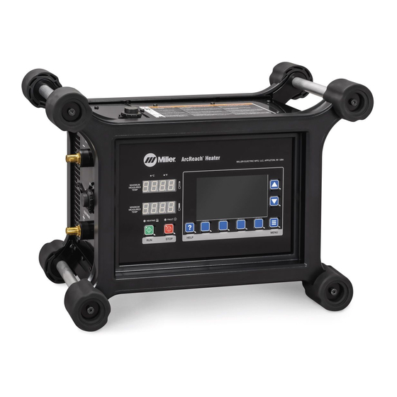
- Page 1 OM-281136A 2019-10 Processes Induction Heating Description Induction Heating Accessory ArcReach Heater With Data Recorder File: Induction Heating For product information, Owner’s Manual translations, and more, visit www.MillerWelds.com...
- Page 2 We know you don’t have time to do it any other way. That’s why when Niels Miller first started building arc welders in 1929, he made sure his products offered long-lasting value and superior quality.
-
Page 3: Table Of Contents
..............B. ArcReach Heater Extension Cable With ArcReach Heater Series Adapter . - Page 4 ..........5-14. Reading ArcReach Heater Extension Cable And Series Adapter Nameplates .
- Page 5 Distance where all general public ELV Exposure Indices fall below 1.00 (100%) 56 cm For applications when more than one FieldPro Heater is used on a common work piece, please contact Miller Electric Mfg. LLC directly for minimum approach distances.
-
Page 7: Section 1 − Safety Precautions − Read Before Using
SECTION 1 − SAFETY PRECAUTIONS − READ BEFORE USING ihom _2019-09 Protect yourself and others from injury — read, follow, and save these important safety precautions and operating instructions. 1-1. Symbol Usage DANGER! − Indicates a hazardous situation which, if Indicates special instructions. -
Page 8: Additional Symbols For Installation, Operation, And Maintenance
FIRE OR EXPLOSION hazard. INDUCTION HEATING can burn. D Do not overheat parts. D Do not touch hot parts bare-handed. D Watch for fire; keep extinguisher nearby. D Allow cooling period before handling parts or equipment. D Keep flammables away from work area. Do not touch or handle induction head/coil during operation un- Do not locate unit on, over, or near combustible surfaces. -
Page 9: California Proposition 65 Warnings
READ INSTRUCTIONS. H.F. RADIATION can cause interference. D High-frequency (H.F.) can interfere with radio D Read and follow all labels and the Owner’s navigation, safety services, computers, and Manual carefully before installing, operating, or communications equipment. servicing unit. Read the safety information at the beginning of the manual and in each D Have only qualified person familiar with elec- section. -
Page 10: Section 2 − Consignes De Sécurité − Lire Avant Utilisation
SECTION 2 − CONSIGNES DE SÉCURITÉ − LIRE AVANT UTILISATION ihom_2018−01_fre Pour écarter les risques de blessure pour vous−même et pour autrui — lire, appliquer et ranger en lieu sûr ces consignes relatives aux précautions de sécurité et au mode opératoire. 2-1. -
Page 11: Dangers Supplémentaires En Relation Avec L'installation, Le Fonctionnement Et La Maintenance
Si la ventilation est médiocre, porter un respirateur anti-vapeurs ap- Ne pas couvrir les protections isolantes refroidies par air avec un prouvé. matériau pouvant entraîner leur surchauffe. Lire et comprendre les fiches de données de sécurité et les instructions Ne pas souder là où l’air ambiant pourrait contenir des poussières, du fabricant concernant les adhésifs, les revêtements, les nettoyants, gaz ou émanations inflammables (vapeur d’essence, par exemple). -
Page 12: Proposition Californienne 65 Avertissements
Demander seulement à des personnes qualifiées familiarisées avec L’EMPLOI EXCESSIF peut SUR- des équipements électroniques de faire fonctionner l’installation. CHAUFFER L’ÉQUIPEMENT. L’utilisateur est tenu de faire corriger rapidement par un électricien qualifié les interférences résultant de l’installation. D Prévoir une période de refroidissement Si le FCC signale des interférences, arrêter immédiatement l’appa- D Réduire le courant de sortie ou le facteur de mar- reil. -
Page 13: Section 3 − Definitions
SECTION 3 − DEFINITIONS 3-1. Additional Safety Symbols And Definitions Some symbols are found only on CE products. Warning! Watch Out! There are possible hazards as shown by the symbols. Safe1 2012−05 Wear dry insulating gloves. Do not wear wet or damaged gloves. Safe56 2017−04 Disconnect input plug or power before working on machine. - Page 14 Keep your head out of the fumes. Safe80 2017−04 Use forced ventilation or local exhaust to remove the fumes. Safe81 2012−07 Use ventilating fan to remove fumes. Safe82 2012−07 Always wear safety glasses or goggles during and around heating operations to prevent possible injury. Safe83 2012−07 Wear either safety glasses or full goggles depending on type of operation and nearby processes.
-
Page 15: Miscellaneous Symbols And Definitions
Hazardous voltage remains on input capacitors after power is turned off. Do not touch fully charged capacitors. Always wait 5 minutes after power is turned off before working on unit, AND check input capacitor voltage, and be sure it is near 0 before touching any parts. >5 min Safe43 2017−04 Connect green or green/yellow grounding conductor to ground... -
Page 16: Section 4 − Specifications
4-1. Serial Number and Rating Label Location The serial number and rating information for the ArcReach Heater is located on the top of the machine. Use the rating labels to determine input power requirements and/or rated output. For future reference, write serial number in space provided on back cover of this manual. -
Page 17: Arcreach Heater Extension Cable With Arcreach Heater Series Adapter
FCC Class A - 2019-10 ISED RSS-Gen Issue 5 Requirement The ArcReach Heater Extension Cable contains licence-exempt transmitter(s)/receiver(s) that comply with Innovation, Science and Economic Development Canada’s licence-exempt RSS(s). Operation is subject to the following two conditions: 1. This device may not cause interference. -
Page 18: Air-Cooled Quick Wrap
E. Air-Cooled Quick Wrap Always use air-cooled quick wrap with sleeve installed. Ref. 279589-A / Ref. 282491-A Dimensions Part Pipe Fit Diameter (w/Blanket Insulating Pad Weight And Sleeve) 301452 78 in. 3.7 in. 6.5 in. 2.4 in. 62.75 in. Min. 1.5 in. (38.1) 15 lb Max 10 in. -
Page 19: Section 5 − Installation
Ref. oc_dynasty 2015-04 5-2. Selecting Weld Cable Sizes The ArcReach Heater requires 2/0 (70 mm) minimum cable size to minimize voltage drop in the cable. Ensure cable connecters are clean and tight to minimize voltage drop in the connectors. Maximum cable length is 200 ft (61 m) from welding power source, 400 ft (122 m) total loop length. -
Page 20: Connecting To A Welding Power Source
Some TIG machines have a low output voltage option, below the 28 volts required by the ArcReach Heater. See the power source Owner’s Manual for instructions on adjusting the minimum voltage, or set the power source for MIG or Stick mode before connecting the ArcReach Heater. -
Page 21: Connecting Arcreach Heater Extension Cable With Series Adapter
5-4. Connecting ArcReach Heater Extension Cable With Series Adapter ArcReach Heater ArcReach Heater Panel Connector ArcReach Heater Extension Cable Connector Plug ArcReach Heater Extension Cable with Series Adapter Panel Connector Locking Tabs Align pins of cable connector plug and ArcReach Heater panel connector. -
Page 22: Insulation Fault Detection
5-5. Insulation Fault Detection Sense lead must be connected for insulation fault detection cir- cuit to function. The ArcReach Heater employs sec- ondary insulation leakage test circuitry consisting of an AC test voltage (im- posed upon the output conductors), and... -
Page 23: External Indicator (If Equipped)
The External Indicator connector is a dry contact rated for 24V AC/DC, 0.25A max. The contact will close when the blue heating light on the ArcReach Heater and TC Extension cable are lit, and will open when the red fault light is lit or Stop is pressed on the ArcReach Heater. -
Page 24: Installing Air-Cooled Heating Cables
Turn off heater output. Use proper tools and/or wear heavy, insulated welding gloves and clothing to prevent burns. Keep heating tool leads between ArcReach Heater Extension Cable and workpiece together to increase heating performance and minimize unintentional heating of nearby objects. -
Page 25: Metal Plate Installation
Turn off heater output. Use proper tools and/or wear heavy, insulated welding gloves and clothing to prevent burns. Read welding power source and ArcReach Heater owner’s manual before installing series adapter. Used to connect two heating cables on large parts. -
Page 26: Cable Length Installation Chart
D. Cable Length Installation Chart Cable lengths determined with: S Insulation - 1 in.(2.5cm) S Cable Loop Distance - 24 in.(61cm) S Cable Off Pipe - 24 in.(61cm) Cable Length Required For Cable Length Required For Cable Length Required For Pipe Size 2 Turns Per Side 3 Turns Per Side... -
Page 27: Determining Length Of Starting Lead For Insulation With Straps
E. Determining Length Of Starting Lead For Insulation With Straps Starting Lead To determine the length of the start- ing lead, subtract the required cable length (from table in Section 5-8-E), from the length of the heating cable being used, divide by 2, and sub- tract 6 inches to account for the hose bunching up while winding the coil. -
Page 28: Connecting Thermocouples
TC positions while heating The monitor thermocouple can be con- ArcReach Heater extension cable. trol or monitor. Thermocouples do not need to be sequential; they can skip a slot if needed. -
Page 29: Connecting Thermocouples (Continued)
TC not under the heating wrap or cable. S Before sliding the coils away from the joint, press [Stop] on the ArcReach Heater to de-energize the output. S When the cables are slid away from the joint to maintain temperature for the welding process, the TC away from the joint (now under the coils) must be set as a control TCs well. -
Page 30: Installing Air-Cooled Quick Wrap (Also See Sections 5-12 And 5-13)
Two quick wraps can be used to cover a wider heat zone to introduce more power into a larger part. Keep heating tool leads between ArcReach Heater extension cable workpiece together increase heating performance minimize unintentional heating of nearby objects. -
Page 31: Installing Air-Cooled Quick Wrap (Continued)
5-12. Installing Air-Cooled Quick Wrap (Continued) Air-Cooled Quick Wrap Housing Connectors Housing Connector Latching Handle Cinch Clip, Latch Cinch Clip Left Side Right Side Ref. 282308-A OM-281136 Page 25... -
Page 32: Installing Air-Cooled Quick Wrap (Continued)
5-13. Installing Air-Cooled Quick Wrap (Continued) Do not hang cables on steel brackets, hangers, or other mechanisms. Position quick wraps reasonably close to the weld joint to decrease the time spent to reach the desired temperature. Heat from the weld process can damage the heating tool. -
Page 33: Reading Arcreach Heater Extension Cable And Series Adapter Nameplates
5-14. Reading ArcReach Heater Extension Cable And Series Adapter Nameplates The built in series adaptor is needed if two heating tools are being used. ArcReach Heater Extension Cable Nameplate Single Tool w/Horizontal Connections single air-cooled cable air-cooled quick wrap connects from A to B on the upper box. -
Page 34: Connecting Heating Tool Cables To Thermocouple Extension Cable Receptacle
Heating Tool Connector Socket Heating Tool Connector Plugs Connect the air-cooled heating cable or air-cooled quick wrap connector plugs to the heating tool connector sockets at the end of the ArcReach Heater extension cable. Twist connector clockwise to secure in place. 1 Tool Ref. -
Page 35: Current Flow
The operating parameters in the quick wrap are affected by the polarity of the leads connected to the ArcReach Heater extension cable. Some applications may make it difficult to see which lead is which on the quick wrap. -
Page 36: Connecting Thermocouples Temperature Sensors
Connector Plugs Connect all thermocouple temp sen- sor connector plugs to the thermo- couple receptacle at the end of the ArcReach Heater extension cable. Thermocouples do not need to be sequential; they can skip a slot if needed. For example, con- necting TC1 and TC3 only. -
Page 37: Complete Setup Summary
5-19. Complete Setup Summary Works up to 200 ft (61 m) away. Route thermocouple (TC) cables separate from heating cables / leads to prevent interaction. Do not disconnect cables during heating process. Press Red Stop button to stop the heating process before disconnecting cables. -
Page 38: Section 6 − System Controls And Components
SECTION 6 − SYSTEM CONTROLS AND COMPONENTS 6-1. System Controls OPEh OPEh Ref. 276675-B Run Button Scroll Up/Down Buttons 10 Minimum Temperature Display Press button to navigate through the Press button to start output. Display will read OPEN when no options list. -
Page 39: Section 7 − Operation
• Assemble ArcReach Heater system. Install system in proper location and near workpiece to be heated. • There is no power switch on the ArcReach Heater. The unit will power up when it is plugged into an active power source. -
Page 40: Initial Setup
7-3. Initial Setup Figure 7-2. Temperature Screen On power-up, the ArchReach Heater will display the Temperature screen. A. Setting Up Time Zone Figure 7-3. Time and Date Screen To set the time zone, follow these steps: 1. Press [Menu]. 2. Highlight [Time and Date] by pressing [Up/Down Arrows]. 3. -
Page 41: System Settings
B. System Settings Figure 7-4. System Settings Screen Color Scheme (Light/Dark Mode), Temperature Unit (C/F), and Time Format (12/24 hr time) can be changed in the system settings screen: 1. Press [Menu]. 2. Highlight [System Settings] by pressing [Up/Down Arrows]. 3. -
Page 42: Selecting Control Thermocouples
C. Selecting Control Thermocouples Figure 7-5. Manage Control Thermocouples Screen 1. Press [Manage Control TCs] on the temperatures screen to select which thermocouples control the heating process. The Manage Control Thermocouples screen shows the available Thermocouples (TCs). An indicator at the left of each TC shows whether it is set as a control. -
Page 43: Preheating Without A Loaded Program
7-4. Preheating Without A Loaded Program 1. Ensure all control thermocouples (TCs) are securely located under the attached heating tools and in positive contact with the part to be heated. The attached TCs will display sensor temperatures. 2. Press [Run] to start the heating process. The recording indicator will flash and the recording timer will display duration of the heat cycle. 3. -
Page 44: Bakeout Temperature Screen
A. Bakeout Temperature Screen Figure 7-7. Bakeout Heating No Preconfigured Loaded Program Screen B. Bakeout Sequence Screen Heating Screen Ramping Screen Soaking Screen Bakeout Complete Screen Figure 7-8. Bakeout Sequence Screens OM-281136 Page 38... - Page 45 Figure 7-9. Stop Recording Message Even though a preloaded program may not have been used, the heat profile is still recorded and the data can be saved to a USB drive. See Section 7-7 OM-281136 Page 39...
-
Page 46: Heating From A Preconfigured Loaded Program From Pc Data App
Loading a Program: 1. Insert a USB drive into the USB receptacle on the left side of the ArcReach Heater. The USB drive is automatically detected and a menu is displayed. Highlight [Load Program] with [Up/Down Arrows] and press [Select]. -
Page 47: Start Heating
B. Start Heating 1. Ensure all control thermocouples (TCs) are securely located under the attached heating tool and in positive contact with the part to be heated. The attached TCs will display sensor temperatures 2. Press [Run] to start the heating process. The recording indicator will flash and the recording timer will display duration of the heat cycle. 3. -
Page 48: Saving Data To Usb Drive
Figure 7-13. USB Menu Screen 1. Insert a USB drive into the USB receptacle on the left side of the ArcReach Heater. The USB drive is automatically detected and a menu is displayed. 2. Press [Up/Down Arrows] to highlight Save Temperature Data and press [Select]. -
Page 49: Heating Parameters
Tool Limit ArcReach heating tools communicate their identity and power limits to the TC extension cable. The amperage limits for the tool are displayed in the tool limit column. For example, the air−cooled heating cable displays 250/200 which means it can run at 250A for 15 minutes, then is restricted to 200A continuous. -
Page 50: Adjust Limits
7-9. Adjust Limits Figure 7-16. Adjust Limits Screen Sometimes the heating control loop may not be optimized for the size or material of the part being heated. The Power (KW), Current (A) and Voltage (V) limits can be reduced on the Adjust Limits screen in the System Menu. This will result in less power to the part and a longer time to temperature. -
Page 51: Update System
7-10. Update System Figure 7-17. Update System Screen When No USB Drive Detected The Update System screen allows you to update the current system using a USB drive. To update the system, a USB with a valid system software update file must be plugged in. The version number of the current system is shown at the top of the screen. -
Page 52: Fault History
7-11. Fault History Figure 7-19. Fault History Screen If a fault was closed (not cleared) on a previous screen, the fault must be manually cleared through the Fault History screen. Press [Menu], then press [Up/Down Arrows] to highlight the Fault History field. Press [Select] to open the Fault History screen. To view details of a specific fault, select it by pressing [Up/Down Arrows], then press [Show Detail]. -
Page 53: System Diagnostics
The System Diagnostics screen shows technical information that may be useful for troubleshooting, technical support and service. Nothing on this screen can be edited. 7-13. About Screen Figure 7-22. About Screen The About screen displays information about the ArcReach Heater’s hardware and software. This information may be useful for technical support and service. OM-281136 Page 47... -
Page 54: Section 8 − Pc Data Application
SECTION 8 − PC DATA APPLICATION 8-1. ArcReach Heater Data Application For Preconfigured Heat Files Windows 10 Download Instructions The download/install link for the ArcReach Heater data application is listed below. https://www.millerwelds.com/support/software/arcreach-heater-software From the download page click on [Download ArcReach Heater Data Application] Figure 7-23. - Page 55 Follow the on-screen prompts to install the application. Press [Finish] to close the install program window. Figure 7-25. Install Wizard Screen The ArcReach Heater data program will open automatically after install. Figure 7-26. ArcReach Heater Joint Setup Screen OM-281136 Page 49...
- Page 56 The application will be available from the shortcut installed on the desktop, or in the start menu under Miller \ ArcReach Heater Data Application. To open the application, navigate to the link in the start menu and click to start the application. The Miller logo will display in the task bar when the program is open.
- Page 57 This feature is also useful when two ArcReach Heaters are used to heat one joint. A temperature data file will be created by each of the ArcReach Heaters. The merge temperature files feature will allow the user to combine these files from two heaters into one temperature file.
- Page 58 This setup file is transferred to the ArcReach Heater using a 32GB max USB memory stick. Press [Joint Setup] at the left side of the screen to open the Joint Setup screen.
- Page 59 Temperature Chart This feature allows a user to view temperature data that was recorded when using the ArcReach Heater to heat a joint. When viewing the data, the joint setup information and a temperature data chart are displayed. The temperature data can also be printed, exported to a csv (Excel) file, or exported to a pdf.
- Page 60 Maximum Temperature − The maximum allowable temperature of the joint to be heated. ArcReach Heater Serial Number − The serial number of the ArcReach Heater(s) used to heat the joint. Output Ext Identifier − The serial number of the output extension(s) used to heat the joint.
-
Page 61: Section 9 − Maintenance And Troubleshooting
SECTION 9 − MAINTENANCE AND TROUBLESHOOTING 9-1. Routine Maintenance Disconnect power before maintaining. Maintain more often during severe conditions. A. ArcReach Heater n = Check Z = Change ~ = Clean Δ = Repair l = Replace * To be done by Factory Authorized Service Agent... -
Page 62: Section 10 − Electrical Diagrams
SECTION 10 − ELECTRICAL DIAGRAMS 276180-A Figure 10-1. Circuit Diagram For ArcReach Heater OM-281136 Page 56... - Page 63 Notes Welding Tip: Securely connect work clamp to a clean area close to the weld joint.
- Page 64 Notes Invision 354MP TM-188 304 Page 58...
- Page 65 Notes MATERIAL THICKNESS REFERENCE CHART 24 Gauge (.025 in.) 22 Gauge (.031 in.) 20 Gauge (.037 in.) 18 Gauge (.050 in.) 16 Gauge (.063 in.) 14 Gauge (.078 in.) 1/8 in. (.125 in.) 3/16 in. (.188 in.) 1/4 in. (.25 in.) 5/16 in.
- Page 66 Effective January 1, 2019 (Equipment with a serial number preface of MK or newer) This limited warranty supersedes all previous Miller warranties and is exclusive with no other guarantees or warranties expressed or implied. LIMITED WARRANTY − Subject to the terms and conditions Subarc Wire Drive Assemblies below, Miller Electric Mfg.
- Page 67 Contact the Delivering Carrier to: File a claim for loss or damage during shipment. For assistance in filing or settling claims, contact your distributor and/or equipment manufacturer’s Transportation Department. © ORIGINAL INSTRUCTIONS − PRINTED IN USA 2019 Miller Electric Mfg. LLC 2019−01...
Need help?
Do you have a question about the ArcReach and is the answer not in the manual?
Questions and answers