Table of Contents
Advertisement
Advertisement
Table of Contents

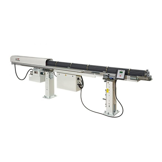
Summary of Contents for LNS TRYTON 112
-
Page 2: Table Of Contents
START UP MANUAL TABLE OF CONTENTS SETTINGS RELATED TO INSTALLATION End of bar position Top-cut position MECHANICAL SETTINGS Changing the collet Feed pressure and speed Adjusting the jaws Hybrid barrel (option) LATHE SET-UP Spindle reduction tubes Profiled bars TRYTON 112 CNC... -
Page 3: Settings Related To Installation
C The maximum remnant length (Max) is obtained when there is not enough material for machining an additional part (Lp - 1 mm). Maximum remnant length = Lp - 1 mm + Min TRYTON 112 CNC... - Page 4 Draw back the pusher then advance it again to ensure that it stops in the set position. Screw-cutters and lathes with mobile headstocks • Set the end-of-bar 5 mm behind the chuck jaw, when the headstock is in the rear-of- part position. TRYTON 112 CNC...
-
Page 5: Top-Cut Position
This positioning corresponds to a value (Z) programmed by the operator, which is equal to the distance between the measuring cell and the position of the material in the lathe clamping device. With this system, the setting is the same for any bar length. TRYTON 112 CNC... - Page 6 **** MM 5. Enter the new value with the numerical keys 6. To validate the new TOP CUT position, keep [ENTER] pressed until the icon disappears. 7. To exit the set mode, press the [MENU] or [STOP] key. TRYTON 112 CNC...
-
Page 7: Changing The Collet
5. Unscrew (1) the collet (A) of the rotating ferrule (B), then strip (2) the elements. Install the new collet. 6. With the stationary control, move pusher back into the connector. 7. To exit adjustment mode, to press the [MENU] or [STOP] key. TRYTON 112 CNC... -
Page 8: Feed Pressure And Speed
(C) slowly until the pressure falls. Reopen until the pressure stabilises. In this position, the feed speed is at its minimum. To increase it, unscrew the regulator (C). Important : For the pressure to be adjusted, the speed regulator must not be closed completely TRYTON 112 CNC... -
Page 9: Adjusting The Jaws
Pull the bar and move it up to the collet Loosen the locking knobs (B) of the upper and lower jaws of the mobile vice Loosen the nuts (C) then the bolts (D) of the upper and lower jaws (E), so that they open (2). TRYTON 112 CNC... - Page 10 Return the bar to the loading position. Advance the mobile vice. Advance the connector and check that the bar is gripped and correctly inserted into the collet. Then, move the connector back to check that the rod is correctly extracted. TRYTON 112 CNC...
-
Page 11: Hybrid Barrel (Option)
3. Unscrew the bolt (C) and remove the connector block (D), taking care not to damage the cable (E). Place the connector block on the support provided for that effect. 4. Unscrew the cable (E) from the pusher (F). TRYTON 112 CNC... - Page 12 7. Secure the ferrule with the cotter-pin (A). tubes. 8. More the connector to its rearmost position with the stationary control. 9. Index the barrel by one tube by pressing the LOAD button on the stationary control. TRYTON 112 CNC...
-
Page 13: Lathe Set-Up
(diameter of the bar + 1 mm), but should always be larger than that of the diameter of the feeding pusher. Spindle reduction tubes are available from LNS, upon request 3.2 Shaped bars (hex and square) It is possible to install a bushing, inside the clamping device, with the same inside profile Note : (+ 0.2 mm) as the bar.


Need help?
Do you have a question about the TRYTON 112 and is the answer not in the manual?
Questions and answers