Table of Contents
Advertisement
Advertisement
Table of Contents

Related Manuals for LIFAN Power USA STORM Series


Summary of Contents for LIFAN Power USA STORM Series
- Page 2 THANK YOU FOR YOUR PURCHASE PLEASE READ!!!!! L I F A N P O W E R U S A Page 1...
- Page 3 Operating Instructions Owner’s Manual ENERGY STORM INVERTERS ESI 2500iER-EFI-CSA ESI 3100iER-EFI-CSA 50 States Compliant and Canada Record Purchase Here Model # ___________________________ Engine ID # _________________________ (Unique Identifier stamped on engine crankcase) Date of Purchase ____________________ Purchase Location ___________________ PLEASE KEEP AND READ THIS MANUAL CAREFULLY BEFORE OPERATING YOUR NEW DIGITAL INVERTER GENERATOR (EFI) INDICATES THIS UNIT EQUIPPED WITH ELECTRONIC FUEL INJECTION (i) INDICATES THIS UNIT WQUIPPED WITH THE AUTO IDLE FEATURE...
- Page 4 PLEASE READ THE FOLLOWING INSTRUCTIONS! 1. Unit Shipped with “NO OIL” in Engine or where applicable pumps and/or accessories. Check and fill with proper oil as outlined in the Owner’s Manual for the respective product. 2. For repair under Warranty or questions concerning Warranty, DO NOT return this product to the Store where purchased.
- Page 5 Automotive Type Electronic Fuel Injection System EnergyStorm EFI computer-controlled fuel and ignition system This generator has a computer-controlled fuel and ignition system. An on-board computer, referred to in this manual as an ECU (Engine Control Unit) utilizes a series of virtual maps (lookup tables) that provide values for various aspects of engine performance.
-
Page 6: Table Of Contents
Table of Contents Preface Product Specifications Generator/Safety Instructions Controls and Features PRE- - O PERATING INSTRUCTIONS Assembly Generator Setup Understanding Your Battery Operation of Generator Storing the Unit Maintenance Transporting The Generator Long Term Storage Troubleshooting Wattage Chart Limited Warranty Policy Appendix Wiring / Exploded View Diagrams L I F A N P O W E R U S A... -
Page 7: Preface
Preface Thank you for choosing LIFAN Power USA for your Power Equipment Needs. LIFAN Power USA prides itself on providing quality products at affordable pricing, creating the “Best Equipment Value on Today’s Market!” All LIFAN Power USA products are manufactured utilizing the latest technology as seen with your new EFI technology. Built with quality components, your new Power Equipment Product will give you years of dependable service. -
Page 8: Product Specifications
Specifications ENERGY STORM INVERTER GENERATORS ESI 2500iER-EFI-CA ESI 3100iER-EFI-CA Model Size Voltage 120V AC 120V AC 2500 Watts 3100 Watts AC Surge Output 2400 Watts 2900 Watts Rated AC Output Maximum AC Amperage 20 amps 22 amps AC Cycle 60 Hertz 60 Herts 120V 20amp AC Receptacle 2 ea. -
Page 9: Generator/Safety Instructions
Generator Safety 1. Never operate gasoline engine powered products in any enclosed spaces, as they product deadly Carbon Monoxide Poisonous Gases. 2. Never hook a generator directly to your home circuit without the proper installation by a Licensed Electrician and without the proper power transfer devices. 3. - Page 10 SAFETY RULES For your safety read this manual carefully. The proper operation care and maintenance of your Lifan generator. WARNING! The safety and alert symbol ( A ) is used with a signal word (CAUTION, DANGER, WARNING), a pictorial and/or safety message sprains, alert you to hazards.
- Page 11 WARNING! Fuel and its vapors are extremely flammable and explosive. Fire or explosion can cause severe burns or death. WHEN ADDING OR DRAINING FUEL Turn generator off and let it cool for at least three minutes before removing fuel cap. Loosen cap slowly in order to relieve pressure in the fuel tank.
- Page 12 WARNING! While engine is running temperature may exceed 150°F (65°C). Server burns may occur. Exhaust heat/gasses can ignite combustibles, structures or damage fuel tank causing a fire. Do NOT touch hot surfaces and do avoid exhaust gasses. Allow generator to cool before touching. ...
- Page 13 Safety Instructions (continued) WARNING! Fuel and its vapors are extremely flammable and explosive. Fire or explosion can cause severe burns or death. WHEN ADDING OR DRAINING FUEL Turn generator off and let it cool for at least three minutes before removing fuel cap. Loosen cap slowly in order to relieve pressure in the fuel tank.
-
Page 14: Controls And Features
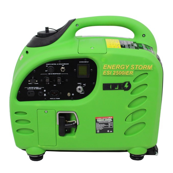
Controls and Features Read this Owner’s Manual completely and carefully before Operating Generator ESI 2500iER-EFI-CA ESI 3100iER-EFI-CA L I F A N P O W E R U S A Page 13... - Page 15 Controls and Features (continued) Read this Owner’s Manual completely and carefully before Operating Generator. Model - ESI 2500iER-EFI-CA Rear Vent Control Panel Recoil Start ESI 2500iER Right Access Panel Fuel Tank Cap Left Access Panel Fuel Switch L I F A N P O W E R U S A Page 14...
- Page 16 Controls and Features (continued) Read this Owner’s Manual completely and carefully before Operating Generator. Model - ESI 3100iER-EFI-CA Fuel Tank Cap Rear Vent Control Panel Left Access Panel Left Access Panel Rear Wheels Recoil Start L I F A N P O W E R U S A Page 15...
- Page 17 Legend 1. Control Panel-Varies between each model. 2. Left Access Cover-Remove for Maintenance - Air Cleaner Element, etc. 3. Fuel tank Cap-Opening to fuel tank for re-- fueling. NOTE: Ensure Fuel Tank Cap is securely fastened before use. 4. Muffle Cover-Plastic Grating covering muffler 5.
-
Page 18: Pre- - O Perating Instructions
Pre--‐Operating Instructions: Assembly Your LIFAN Power USA generator is packaged without fuel and oil. Some assembly is required before operating your LIFAN Power USA Generator. BOX CONTENT: Generator Accessory Kit o Spark Plug Removal Tool o 1 ea. – Oil Drain Tube o 1 ea. -
Page 19: Generator Setup
Pre--‐Operating Instructions: Generator Setup CAUTION: Any attempt to start the generator before it has been properly serviced may result in engine failure and void warranty. ADD ENGINE OIL: Refer to the diagrams below. 1. Place generator on level surface. 2. Remove the left Access Panel (Refer to Controls and Features section). 3. - Page 20 Pre--‐Operating Instructions: Generator Setup WARNING! Fuel and its vapors are extremely flammable and explosive. Fire or explosion can cause severe burns or death. WHEN ADDING FUEL Turn generator off and let it cool for a minimum of three minutes before removing fuel cap. Turn and remove cap slowly in order to relieve residual tank pressure.
- Page 21 Pre--‐Operating Instructions: Generator Setup CAUTION: Any attempt to start the generator before it has been properly serviced may result in engine failure and void warranty. CHECK AIR CLEANER ELEMENT: Refer to diagram below. 1. Remove the Left Access Cover (Refer to Controls and Features section). 2.
- Page 22 Pre--‐Operating Instructions: Generator Setup CAUTION: Any attempt to start the generator before it has been properly serviced may result in engine failure and void warranty. GROUNDING THE GENERATOR: Refer to the diagram below. 1. Connect the Ground Terminal on the generator to an acceptable source of electrical ground, such as a copper- - ...
-
Page 23: Understanding Your Battery
Understanding Your Battery When the key is turned to the ON position the display illuminates, the ECU turns on, the fuel pump turns on long enough to bring up the fuel pressure, and the stepper motor is energized for proper throttle position for starting. Because of the power requirements of these components, the battery in this generator is considered dead at a higher voltage than it would be in other types of equipment. - Page 24 Understanding Your Battery (Continued) If the generator will not start, check the battery voltage with a voltmeter. You can access the battery through the left maintenance door, or you can simply check the voltage through the battery charge receptacle on the control panel. This receptacle is connected directly to the battery, so it can be used without the generator running, or the key in the ON position, or the remote switch on.
- Page 25 Battery Charger/Maintainer Instructions (For use with models ESI 2500iER-EFI-CA and ESI 3100iER-EFI-CA) Thank you for your purchase of your new EnergyStorm Digital Inverter Generator. As our way of saying “thank you” please find packaged in your unit our new Battery Trickle Charger/Battery Maintainer for your Inverter Generator. When you store your unit for long periods of time, any period exceeding 30 days, you can utilize your Battery Trickle Charger/Maintainer to keep your battery in a charged condition or if you have allowed your battery to become completely discharged it can be used to re-charge your battery however this will take an extended period of time,...
-
Page 26: Operation Of Generator
Operation of Generator HOW TO USE YOUR GENERATOR GENERATOR LOCATION: • To prevent electrical shock from faulty appliances, the generator should be grounded. Connect a length of heavy cable between the generator's grounding terminal and an external ground source. • This generator is not intended, nor designed, for use as a standby power supply, or to be connected to an automatic transfer switch (ATS);... - Page 27 Operation of Generator • Keep the generator away from other electric cables or wires such as commercial power supply lines. • The DC receptacle (in the Battery Charge section of the control panel) can be used while the AC power is in use. If you use both at the same time, be sure not to exceed the total power for AC and DC.
- Page 28 Operation of Generator HOW TO USE YOUR GENERATOR (continued) ELECTRIC/PULL (RECOIL) START MODELS: 4. Using provided key, turn the ignition switch to the “ON” position. Rotate the key one more position to the “START” position in order to engage the starting motor. Hold key switch in the “START” position until engine starts, for NO MORE than 10 engine rotations.
- Page 29 Operation of Generator CONNECTING ELECTRICAL LOADS: 1. Ensure engine is started and Green Indicator Light illuminates before plugging in any electrical appliance. 2. Plug in desired 120 Volt load to the 120 Volt U- - G round receptacles or the 120 Volt NEMA 14--30 twist lock receptacle.
- Page 30 Operation of Generator This generator has been designed to prevent the engine from “overspeed” revving. Overspeed revving occurs when a generator’s on-board monitoring systems detect a drop in voltage from the inverter, and the generator attempts to compensate by revving the engine higher to generate more electricity. In the rare event of an inverter failure, there will be no voltage output from the inverter, and the engine will remain revving at or close to its top speed.
- Page 31 Operation of Generator LOW OIL ALARM SYSTEM: This model is equipped with a Low Oil Alert System designed to avoid engine damage from insufficient oil in the crankcase. The Low Oil Alarm System will stop the engine automatically before the oil level in the crankcase drops below safe operating levels.
-
Page 32: Storing The Unit
Operation of Generator HOW TO USE YOUR GENERATOR (continued) USAGE IN HIGH ALTITUDE REGIONS: At high altitude, performance will decrease. Even with the fuel injection system in this generator, engine horsepower will decrease approximately 3.5% for each 1000 feet (305 meters) increase in altitude. At higher altitudes, the density of the atmosphere decreases, so there is less oxygen volume to draw into the cylinder. -
Page 33: Maintenance
Maintenance NOTE: Refer to Following Procedures for Proper Method to Perform Maintenance Maintenance Schedule Maintenance Item Regular Service period (1). Perform at every indicated month or operating Procedure hour interval, whichever occurs first. Each Use 1st Month or 4 Every 3 Months Every 6 Months 1x per Year or to 6 Hours... - Page 34 Maintenance (continued) OIL CHANGE PROCEDURES: Periodic Maintenance of your engine oil should be performed after each 40 hours of use of you Power Equipment Product. Check your engine oil level prior to each use. 1. Start your engine and let it warm up to get the oil warm and thinner. Turn the ignition switch to the “STOP” position.
- Page 35 Maintenance (continued) AIR CLEANER MAINTENANCE: Refer to Controls and Features section for diagram. 1. Remove Left Access Cover. 2. Remove the Air Cover Case. 3. Pull out the Air Cleaner cartridge following the direction of the arrow. 4. Check the Air Cleaner Element for cleanliness. If needed clean/replace Air Cleaner Element. 5.
- Page 36 Maintenance (continued) SPARK PLUG MAINTENANCE: Recommended spark plug: F7RTC To ensure proper engine operation, the spark plug must be properly gapped and free of deposits. 1. Loosen the cover screws and remove the maintenance door. 2. Remove the spark plug cap. 3.
- Page 37 Maintenance (continued) Fuel Filter Element Removal Fuel Filter Element Assembly • If the generator has been running, the muffler will be very hot. Allow it to cool before proceeding. Spark Arrestor: • The spark arrester must be serviced every 100 hours to maintain its efficiency, or a decrease in Horsepower may occur.
-
Page 38: Transporting The Generator
Transporting the Generator To prevent fuel spillage when transporting or during temporary storage, the generator should be secured upright in its normal operating position with the ignition switch and remote switch turned “OFF”. When transporting the generator: • Do not operate the generator while it is on or in a vehicle. •... -
Page 39: Long Term Storage
Long term storage of the generator During long term storage, the generator should be secured upright in its normal operating position with the ignition switch turned “OFF”. Avoid placing the generator in direct sunlight when storing. • If the generator is left in an enclosed area or vehicle, high temperatures inside could cause residual fuel to vaporize resulting in possible explosion. -
Page 40: Troubleshooting
Troubleshooting IF THE ENGINE WILL NOT START: 1. Check to ensure switches are in the “ON” position. (Both unit and engine) 2. Check engine oil level. Your unit possesses a Low Oil Alarm System that will not allow your engine to start if the oil is below safe operating levels. This feature is installed to increase the life of your engine and prevent engine damage. - Page 41 AC application The control panel has two AC breakers (Circuit Protectors): Two (2) 20 A breakers for the 5-20R split duplex receptacle, and one (1) 10a DC breaker for the DC 12v receptacle. Ensure that the breaker is on for the receptacle you want to use. Start the engine.
- Page 42 Generator Overload • Repeated, substantial overloading that continuously reports an overload condition to the digital display may damage the generator. Marginal overloading that temporarily reports an overload may shorten the service life of the generator. The digital display will remain illuminated and returning data during normal operating conditions. If the generator is overloaded (in excess of 4000 W), or if there is a short in the connected appliance, the values in the digital display will become zero, the message OVER will appear in the wattage (P) field of the display, and the power output will stop.
- Page 43 DC Application You may use the DC receptacle to charge external batteries, to power DC devices, or to back-charge the internal generator battery with a battery charger. The DC receptacle provides a regulated, polarized 12V, 8.3A DC supply. The DC receptacle can be used to back-charge the generator whether the generator is running or not. The generator must be running to charge an external battery through the DC receptacle.
- Page 44 Powering 12V DC devices This generator can be used to power 12V DC devices through the DC receptacle on the control panel while the generator is running. The DC output comes directly from the battery, so powering a DC device places a load on the battery.
- Page 45 Jump-starting the generator This generator was not designed to be jump-started through the DC receptacle and it is not recommended to do so. If you connect an external battery to the DC receptacle before the generator is started and attempt to start the generator with the key fob or the ignition switch, a jump-start may occur, but it will likely trip the DC breaker.
- Page 46 Jump-starting the generator (Continued) Engine will not start Charge the internal battery to at least Does the generator’s internal battery 10.5V. have a charge of at least 10.5V? Replace the fuse. Is the battery fuses missing or burned out? Check all connections between the Take the generator to an authorized battery control panel, and electric starter Lifan Power USA service center...
- Page 47 No output at the DC receptacle Reset the circuit breaker Is the DC circuit breaker tripped? Take the generator to an authorized Lifan Power USA service center Digital display This generator is equipped with an LCD digital display that provides continuously-updated status information for the following parameters: •...
-
Page 48: Wattage Chart
Wattage Chart RUNNING ADDITIONAL STARTING WATTAGE REQUIREMENTS WATTAGE REQUIREMENTS HEATING/COOLING: Furnace Fan, gas or fuel oil furnace 1/8 horsepower 1/6 horsepower 1/4 horsepower 1000 2/5 horsepower 1400 3/5 horsepower 2350 Central Air Conditioner 10,000 BTU 1500 2200 20,000 BTU 2500 3300 24,000 BTU 3800... - Page 49 Washing Machine 2300 Coffee Maker Toaster 2-slice 1100 Toaster 4-slice 1650 Electric Skillet 1500 Electric Range 6-in. element 1500 Electric Range 8-in. element 2100 KITCHEN SUB-TOTAL: APPLIANCES Lights- Wattage Actual: Heating Pad Radio Television - Black & White Television - Color Dehumidifier Electric Blanket Garage Door Opener - 1/4HP...
- Page 50 COMMERCIAL PRODUCTS: Jigsaw Electric Weed Trimmer Router 1000 1000 Belt Sander 1000 1000 Disc Sander 1200 1200 Chain Saw 1200 1200 Worm Drive Saw 1560 3100 12" Concrete Cutter 1800 3600 7 1/4" Circular Saw 1500 3000 Disc Grinder 2000 4000 Air Compressor, Average 2000...
- Page 51 CONVERTING AMPS OR HORSEPOWER INTO WATTS If necessary, uses these formulas: Watts = Amps x Volts Running Watts* = Horsepower x 932** (for motors) Remember, this worksheet lists average power requirements a particular manufacturer's device may use more or less than the listed wattage.
-
Page 52: Limited Warranty Policy
LIMITED WARRANTY POLICY This warranty is limited to the following Lifan Power and Storm Series products that are distributed by the EquipSource LLC, dba LIFAN POWER USA, located at 2205 Industrial Park Road, Van Buren, AR 72956. Effective date is 4/20/2010. - Page 53 LIMITED WARRANTY POLICY This warranty is not valid for products or parts affected or damaged by accident, collision, normal wear, fuel contamination, abuse, neglect, misuse, alteration and/or unsuitable use or unauthorized parts replacement. Mower decks and blades are specifically not warranted for impact or abrasive damage. Warranty becomes void if the customer fails to install, maintain, and/or operate the product in accordance with the instructions and recommended actions of Lifan set forth in the owner’s manual.
- Page 54 This warranty specifically excludes the use of any Lifan Power Equipment or Storm Series power equipment as the "Sole Source of Power" for "off the power grid applications" and this warranty will become null and void for units used for this purpose and manner. This warranty specifically excludes the use of any Lifan Power Equipment or Storm Series power equipment for the purpose of powering Life Support devices, Life Support appliances, Medical devices, and/or Medical appliances.
-
Page 55: Appendix
APPENDIX L I F A N P O W E R U S A Page 54... -
Page 56: Wiring / Exploded View Diagrams
Wiring Diagram ESI2500iER-EFI-CA FME to Insert Wiring Diagram L I F A N P O W E R U S A Page 55... - Page 57 ESI2500iER-EFI-CA Exploded View & Parts FME to Insert Exploded View Diagram L I F A N P O W E R U S A Page 56...
- Page 58 Wiring Diagram ESI3100iER-EFI-CA FME to Insert Wiring Diagram L I F A N P O W E R U S A Page 57...
- Page 59 ESI3100iER-EFI-CA Exploded View & Parts FME to Insert Exploded View Diagram L I F A N P O W E R U S A Page 58...
- Page 60 Please Read this Owner’s Manual Carefully before Operating Your New Inverter Generator. This Owner’s Manual includes the operation and maintenance of the ESI2500iER-EFI-CA and ESI3100iER-EFI-CA Thank you for purchasing our Energy Storm Inverter generator! All information in this publication is based on the latest product information available at the time of approval for printing.
- Page 61 FRENCH ENERGY STORM ™ Générateur onduleur Manuel du propriétaire No. des modèles ESI ESI2500iER–EFI-CA ESI ESI3100iER–EFI-CA L I F A N P O W E R U S A Page 60...
- Page 62 Pour votre sécurité, veuillez lire ce guide attentivement. Familiarisez-vous avec le bon fonctionnement, les soins et l'entretien de votre générateur Energy Storm. Le symbole de sécurité et d’a ) est utilisé avec un mot signal (ATTENTION, DANGER, AVERTISSEMENT), une image et/ou un message de sécurité...
- Page 63 Symboles de danger et leurs significations AVERTISSEMENT! Le générateur produit une tension élevée! Seul un électricien qualifié peut connecter en toute sécurité le générateur aux branchements des services publics existants. Ne pas isoler le générateur du réseau électrique peut entraîner la mort de travailleurs des services publics ainsi que d'autres.
- Page 64 Emplacements des étiquettes de sécurité Ces étiquettes vous avertissent de risques de danger qui peuvent causer des blessures graves. LES LIRE ATTENTIVEMENT. Rear Vent Control Panel Recoil Start ESI 2500iER Right Access Panel Fuel Tank Cap Left Access Panel Fuel Switch L I F A N P O W E R U S A Page 63...
- Page 65 Emplacements des étiquettes de sécurité Ces étiquettes vous avertissent de risques de danger qui peuvent causer des blessures graves. LES LIRE ATTENTIVEMENT. Fuel Tank Cap Rear Vent Control Panel Left Access Panel Left Access Panel Rear Wheels Recoil Start L I F A N P O W E R U S A Page 64...
- Page 66 Emplacements des étiquettes de sécurité Ces étiquettes vous avertissent de risques de danger qui peuvent causer des blessures graves. LES LIRE ATTENTIVEMENT. ESI 2500iER-EFI-CA ESI 3100iER-EFI-CA L I F A N P O W E R U S A Page 65...
- Page 67 Remplissage d’huile de moteur Enlever le couvercle d'accès droit (voir schéma # 56004). Dévisser la jauge d'huile, essuyer la jauge avec un chiffon propre, puis insérer la jauge dans le réservoir d'huile, et vérifier le niveau de l'huile. Si le niveau d'huile est faible ou inférieur à ce qui est recommandé, remplir avec de l'huile recommandé...
- Page 68 Vérifier le niveau de l’essence Do not ù or allow flames or sparks where the generator is refueled or where gasoline is stored. Ravitailler en carburant dans une zone bien aérée avec le moteur arrêté. NE PAS trop remplir le réservoir. Serrer le bouchon du réservoir après l'ajout de carburant. Être prudent et éviter le déversement accidentel d’essence lors de l'ajout de carburant, le carburant déversé...
- Page 69 L I F A N P O W E R U S A Page 68...
- Page 70 Mise à la terre du générateur Avec un fil électrique en cuivre d'un diamètre minimum de calibre 16, connecter la borne de terre du générateur à une source acceptable de masse électrique, tel qu’un pointeau de mise à la terre en cuivre. L I F A N P O W E R U S A Page 69...
- Page 71 Démarrage du moteur Mettre la clé dans le commutateur d'allumage et tourner la clé vers la position 'EN MARCHE'. Tourner la clé du démarrage électrique à la position de “DÉMARRAGE” et lâcher lorsque le moteur démarre L I F A N P O W E R U S A Page 70...
- Page 72 1. Démarrer le lanceur-démarreur (uniquement pour les modèles électriques/lanceur-démarreur) A. Ouvrir le commutateur d’essence B. Placer la clé dans le commutateur d'allumage, et tourner la clé à la position «ON». C. Tirer la corde de démarrage jusqu'à ce que vous sentiez la résistance, puis tirer vigoureusement pour démarrer le moteur.
- Page 73 Vous pouvez utiliser le courant en continu en même temps que vous utilisez l'alimentation en alternatif. Veuillez ne pas dépasser la puissance ou le wattage total du courant en continu et alternatif Faire attention à la puissance de démarrage et les exigences de puissance lorsqu’en marche pour déterminer les éléments à être alimenté...
- Page 74 Lors de l’utilisation de la sortie c.c, tourner le commutateur de marche au ralenti automatique à la position d’arrêt (voir le schéma #56361 pour l'emplacement du commutateur) Vous pouvez utiliser le courant continu et le courant alternatif en même temps. Le circuit saturé...
- Page 75 L I F A N P O W E R U S A Page 74...
- Page 76 2. Système d’alerte d’huile basse (schéma#56014) Le système d'alerte d’huile est conçu pour éviter d'endommager le moteur à cause d’un niveau insuffisant d'huile dans le carter. Le système d'alerte d’huile arrêtera le moteur automatiquement avant que le niveau d'huile dans le carter passe en dessous des niveaux de fonctionnement de sécurité...
- Page 77 Arrêter le moteur avant de faire l'entretien. Si la performance du service nécessite que le générateur fonctionne, VOUS ASSURER de faire fonctionner le générateur dans un environnement bien aéré. L’échappement contient du gaz toxique - monoxyde de carbone, qui peut entraîner la mort. Toujours utiliser des pièces d'origine Energy Storm ou des pièces de qualité...
- Page 78 La capacité du réservoir: Varie selon le modèle. Voir l’autocollant des spécifications sur le générateur L'utilisation d'essence ou de solvant inflammable pour nettoyer le filtre à air peut provoquer un incendie ou une explosion. Utiliser seulement de l'eau savonneuse ou un solvant ininflammable. Vérifier l’élément du filtre à...
- Page 79 1. Inspecter la bougie visuellement. La jeter si l'isolant est fissuré ou ébréché. 2. Veuillez utiliser une jauge à bougie pour vérifier l’écartement de la bougie, il devrait être de 0,6 à 0,7 mm (0,024-0.028 pouce) 3. Vérifier que la rondelle d'étanchéité de la bougie est en bon état, et introduire la bougie à...
- Page 80 Enlever les vis du couvercle d'accès gauche, enlever le couvercle vant d’entreposer le générateur. S’assurer que l'endroit où est entreposé le générateur est propre et sec. Faire marcher le moteur avec le robinet de carburant en position d'arrêt jusqu'à ce que le moteur s'arrête de fonctionner, puis vider le carburant du réservoir d’essence.
- Page 81 Spécifications Taille et poids Item ESI-2500iER-EFI-CA ESI-3100iER-EFI-CA L x P x H 25,5 po x 20 po x 22,25 po 29,5 po x 21,65 po x 31,5 po Poids net 132 livres 144 livres Moteur TYPE 152F 168F Spécification du moteur 4-temps, soupape en tête, monocylindre 6.5-temps, soupape en tête, monocylindre Déplacement...
- Page 82 Unité pleine : 6 mois de pièces et travail Toute laveuse à pression Lifan Pressure Pro™ et Storm Series Pressure Storm™ est équipée d’une pompe à eau haute pression Annovi Reverberi Elles sont couvertes par ™...
- Page 83 Pour bénéficier de cette garantie, vous devez amener le produit, à vos frais, à un centre de service autorisé de produits Lifan Power ou Storm Series Power. Si vous n'arrivez pas à...
- Page 84 SPANISH ENERGY STORM ™ Generador de inversor Manual del usuario Modelo Nº. ESI-2500iER –EFI-CA ESI-3100Ier-EFI-CA ESI 2500iER–EFI-CA ESI 3100iER–EFI-CA L I F A N P O W E R U S A Page 83...
- Page 85 Lea este manual con cuidado para su seguridad. Familiarícese con el funcionamiento, cuidado y mantenimiento apropiado de su generador Energy Storm. El símbolo de seguridad y al ) se utiliza con una palabra de indicación (PRECAUCIÓN, PELIGRO, ADVERTENCIA), un mensaje gráfica y/o mensajes de seguridad para alertar sobre los peligros.
- Page 86 Símbolos de peligro y su significado ADVERTENCIA ¡El generador produce un voltaje muy potente! Sólo un electricista con licencia puede conectar el generador de forma segura a las conexiones de los servicios públicos existentes. Si no se aísla el generador de la red eléctrica puede ocasionar la muerte a los trabajadores de servicios públicos, así...
- Page 87 Ubicaciones de las etiquetas deseguridad Estas etiquetas advierten sobre posibles riesgos que pueden causar lesions graves Model - ESI 2500iER-EFI-CA Rear Vent Control Panel Recoil Start ESI 2500iER Right Access Panel Fuel Tank Cap Left Access Panel Fuel Switch L I F A N P O W E R U S A Page 86...
- Page 88 Model - ESI 3100iER-EFI-CA Fuel Tank Cap Rear Vent Control Panel Left Access Panel Left Access Panel Rear Wheels Recoil Start L I F A N P O W E R U S A Page 87...
- Page 89 Identificación de los componentes Controls and Features Read this Owner’s Manual completely and carefully before Operating Generator ESI 2500iER-EFI-CA ESI 3100iER-EFI-CA L I F A N P O W E R U S A Page 88...
- Page 90 Llenado de aceite del moto Quite la cubierta de acceso de la derecha (consulte el diagrama #56004). Desenrosque la varilla d e aceite, límiela con un paño limpio, luego inserte la varilla en el tanque de aceite y revise el nivel del aceite. Si el nivel de aceite es bajo o inferior al recomendado, llene con el aceite recomendado, utilizando la botella de llenado de aceite (incluida en el paquete de herramientas).
- Page 91 No fume ni permita que haya llamas o chispas cuando abastezca el generador o cuando guarde la gasolina. Llene el tanque en un área bien ventilada y con el motor parado. NO llene demasiado el tanque de combustible. Ajuste la tapa del combustible después de agregar e l combustible. Tenga cuidado y evite derrames de gasolina cuando cargue el combustible, los vertidos del combustible o el humo del gas puede prenderse fuego.
- Page 92 Revise el filtro de aire Saque los tornillos de la cubierta de acceso izquierda y ábrala. Retire los tres tornillos de la caja del filtro de aire. Saque el cartucho de filtro de aire siguiendo la dirección de la punta de flecha. Revise el filtro de aire, limpie o cambie por uno nuevo si es necesario.
- Page 93 Conexión a tierra del generador Con un cable de cobre eléctrico de un diámetro mínimo de calibre 16, conecte el terminal de tierra en el generador a una fuente aceptable de conexión eléctrica a tierra, como una estaca de cobre de puesta a tierra. L I F A N P O W E R U S A Page 92...
- Page 94 A. Coloque la llave en el interruptor de encendido y gírela a la posición de ENCENDIDO. Arranque de retroceso (sólo para modelos con arranque eléctrico/retroceso) L I F A N P O W E R U S A Page 93...
- Page 95 Funcionamiento en áreas de gran altitud A grandes altitudes, la mezcla de combustible/ aire del carburador estándar será demasiado rica. Se reducirá el rendimiento y aumentará el consumo de combustible. El rendimiento a grandes altitudes puede mejorar mediante modificaciones específicas en el carburador. Si siempre utiliza el generador a una altitud superior a 5.000 pies (1.500 metros), por favor, consulte con su Centro de Servicio Autorizado EnergyStorm para configurar adecuadamente el carburador para las grandes altitudes.
- Page 96 3. Aplicaciones Las conexiones para la energía de reserva al sistema eléctrico de un edificio se deben realizar por un electricista calificado. La conexión debe aislar la alimentación del generador de la energía de la red y debe cumplir con todas las leyes y códigos eléctricos aplicables.
- Page 97 Cómo utilizar la energía CA 1. Arranque el motor sin elementos de alimentación eléctrica conectados al generador. 2. Después de que arranque la unidad y se ilumine la luz verde del indicador de salida (ver diagrama Nº 56011) puede saber cómo conectar y utilizar los dispositivos de accionamiento eléctrico.
- Page 98 A. Arranque del motor (consulte la sección 6 para obtener instrucciones) B. Espere cinco segundos para que se encienda la luz verde. Si la luz verde del indicador de salida está apagada, y la luz roja del indicador de sobrecarga está encendida, apague el motor con el interruptor de encendido, luego, siga los requisitos para arrancar y volver a poner en marcha el motor en la sección 6.
- Page 99 No arranque automóviles cuando los generadores están conectados a la batería o se usa la energía CC del generador para arrancar un automóvil, esto puede causar daños en el generador. Siempre asegúrese de hacer coincidir los cables positivos y negativos del cable de alimentación de CC con los polos positivos y negativos de las pilas.
- Page 100 2. Sistema de alarma de baja cantidad de aceite (diagrama Nº. 56014) El sistema de alerta de aceite está diseñado para evitar daños en el motor por cantidad insuficiente de aceite en el cárter del motor, el sistema de alarma de aceite detendrá el motor de forma automática antes de que el nivel de aceite en el cárter esté...
- Page 101 Calendario de mantenimiento Período de servicio regular realizado una Cada vez Todos los Cada 3 Cada 6 Todos los años vez en cada mes indicado o en los que lo meses o meses o meses o o cada 300 intervalos de horas de funcionamiento, lo cada 20 cada 50 cada 100...
- Page 102 Montaje y mantenimiento de la batería (sólo para modelos con arranque eléctrico) a. Saque los tornillos de la cubierta de acceso izquierda y retire la tapa. b. Coloque la batería en la bandeja de la batería, ponga la cubierta de la batería y apriete las tuercas de ajuste. c.
- Page 103 Antes de guardar el generador. Asegúrese de que la ubicación donde se guarda el generador esté limpia y seca. Haga funcionar el motor con la válvula de combustible en la posición de apagado hasta que el motor deje de funcionar. Luego vacíe el combustible del tanque de gasolina.
- Page 104 Especificación del motor 4 tiempos, válvula en la culata, cilindro único 6.5 tiempos, válvula en la culata, cilindro único Desplazamiento 125CC 150CC Relación de compresión 8.5-1 velocidad del motor Variable Variable sistema de enfriamiento Aire Aire Sistema de encendido Capacidad de aceite 32 oz.
- Page 105 Para obtener el servicio de la garantía, debe llevar el producto, a su cargo, a uno de los centros de servicio de Lifan Power Products o Storm Series Power. Si no puede ubicar un servicio de garantía o no está...
- Page 106 Utilización en usos y métodos diferentes a los descritos en el "Manual del Propietario". Servicio y/o reparación realizada por alguien que no sea un "Centro de Servicio para productos Lifan o Storm Series autorizado". L I F A N P O W E R U S A...
- Page 107 L I F A N P O W E R U S A Page 106...
Need help?
Do you have a question about the STORM Series and is the answer not in the manual?
Questions and answers