Advertisement
RESIDENTIAL SALT WATER CHLORINE GENERATOR
Classic Series
INSTRUCTION MANUAL
This manual is for:
CLASSIC RP MODEL RANGE
(FEATURING REVERSE POLARITY TECHNOLOGY)
RP-15, RP-20, RP-25, RP-36, RP-50, RP-64, RP-80
CLASSIC LS MODEL RANGE
(RP20-3500ppm, RP25-3500ppm, RP35-3500ppm)
MIDI RANGE
(RP-100, RP-150)
Includes:
TIME CLOCK MODELS (battery backup optional)
POOL LIGHT MODELS (where fi tted)
Advertisement
Table of Contents

Related Manuals for AIS AutoChlor Classic Series

Summary of Contents for AIS AutoChlor Classic Series
- Page 1 RESIDENTIAL SALT WATER CHLORINE GENERATOR Classic Series INSTRUCTION MANUAL This manual is for: CLASSIC RP MODEL RANGE (FEATURING REVERSE POLARITY TECHNOLOGY) RP-15, RP-20, RP-25, RP-36, RP-50, RP-64, RP-80 CLASSIC LS MODEL RANGE (RP20-3500ppm, RP25-3500ppm, RP35-3500ppm) MIDI RANGE (RP-100, RP-150) Includes: TIME CLOCK MODELS (battery backup optional) POOL LIGHT MODELS (where fi tted)
- Page 2 • Australian Innovative Systems Pty Ltd (AIS Water) reserves the right to change the specifi cations of the hardware and software described herein at any time without prior notice.
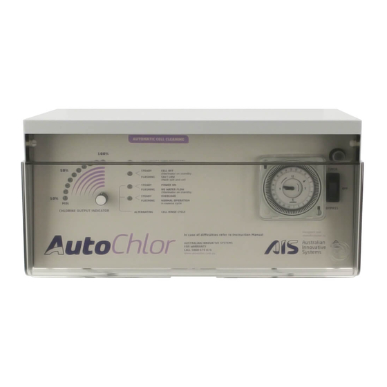
- Page 3 Fig. 1 1. High Salt Light 5. Chlorine Controller If the light is on or fl ashing see Turn clockwise to increase the chlorine Warning Indicator Lights, page 12. output and anti-clockwise to reduce the chlorine output. 2. Low Salt / Cell Off Light If the light on or fl ashing see (Note: When production lights are off , Warning Indicator Lights, page 12.
-
Page 4: Special Note
THE AutoChlor® SALT WATER CHLORINATION SYSTEM Congratulations on your choice of an AutoChlor® salt water chlorinator system for your swim- ming pool. The AutoChlor® salt water chlorinator you have purchased is designed for easy and simplistic operation and maintenance. By following these instructions you are assured years of trouble free operation. -
Page 5: Water Balance
Using only refi ned swimming pool salt add the desired quantity to the swimming pool water. To assist in the rapid dissolving and mixing, sweep or brush the solids until they are fully dis- solved. Undissolved salt may result in staining your pool fi nish. As salt is heavier than water it will continue to lie at the deepest point of your pool, even though the salt granules themselves have fully dissolved. - Page 6 SPECIAL NOTE ON CHLORINE: Your salt water chlorinator is not designed to bring your pool from a zero chlorine read- ing to an acceptable level but rather to maintain acceptable levels. Should it become necessary due to unforeseen circumstances (such as the unlikely event of chlorinator malfunction, severe weather patterns, or massive use of the swimming pool) that you fi...
- Page 7 FITTING THE CHLORINATOR CELL HOUSING The AutoChlor® salt water cell housing must be plumbed into the return line of the pool filter system after the filter and any diversion valves. Please refer to the installation diagram and plumbing outline for the correct method of installation (Fig. 2). In situations where a heater is incorporated, the AutoChlor®...
- Page 9 Convenient, automatic inline salt-water chlorination...
-
Page 10: Installing The Power Supply
INSTALLING THE POWER SUPPLY The AutoChlor® power supply is mounted on a wall using the mounting bracket and fi ttings supplied. After securing the bracket in the appropriate position relative to your needs, the power supply is hung on the bracket and locked into position by ensuring that the unit slips into the slots provided on the mounting bracket. -
Page 11: Circuit Breaker
POWER SUPPLY CONTROL FUNCTIONS Your AutoChlor® salt water chlorination system has been designed for simplistic operation and control. The functions and controls (both standard and optional) and their various operations will give you a greater understanding and knowledge of the control and maintenance of both your AutoChlor®... -
Page 12: Warning/Indicator Lights
WARNING INDICATOR LIGHTS (FIG. 1, ITEMS 1, 2, 3 & 4) There are four (4) warning indicator lights located on the front of your chlorinator. These advise at a glance the status of the chlorinator power supply and, when illuminated they indicate and advise about the situation that the chlorinator’s electronic monitoring system has detected. - Page 13 4. RED LIGHT: STEADY OVERLOAD NORMAL OPERATION in forward cycle FLASHING NORMAL OPERATION (RP MODEL ONLY) in reverse cycle STEADY – When this light is illuminated and STEADY it will also be accompanied by a beeping alarm alerting you of this situation. The chlorinator has overloaded and shut down to prevent any damage.
- Page 14 CHLORINE CONTROLLER (FIG. 1, ITEM 5) The chlorine controller regulates the amount of chlorine production relevant to the position it has been set to. By adjusting the chlorine controller clockwise you increase chlorine manufac- ture and by turning anti clockwise you reduce production. Do not attempt to turn the controller beyond its stops as this could cause damage to your unit that is not covered by warranty.
- Page 15 SPECIAL NOTE ON TIMERS (TIMER MODELS ONLY): If you require your AutoChlor® salt water chlorinator to be connected to a cheaper o peak tari we recommend the use of an appropriate quartz time clock for that purpose. The unit may also be hard wired in however, in case of incorrect wiring or damage caused by modifi...
- Page 16 UNDER WATER POOL LIGHTS (POOL LIGHT MODELS ONLY) Where requested, and as an optional extra, some AutoChlor® models have swimming pool under water light transformers fitted. This special transformer allows you to connect your pool light lead to the special connection supplied and operate them from the chlorinator power supply.
- Page 17 Normally once set, these controls do not require further adjustment except perhaps for the seasonal ones suggested earlier. Set your chlorine controller to achieve maximum and optimum results for your pool situation. Please remember that an over chlorinated pool is not a healthy pool, so it may not be nec- essary for you to run your chlorinator at maximum output to maintain recommended chlorine levels.
- Page 18 CHLORINATOR RUNNING TIMES Chlorinator running times will vary from pool to pool, and are dependent upon the situation they are installed into, pool size and the overall usage of the pool in general. Several factors will determine the operational time of the chlorinator to be able to produce sufficient chlorine for your pools requirements: TIME: The longer you run your filter plant and chlorinator, the more chlorine you will produce.
-
Page 19: Maintenance
Therefore, inspection and cleaning outside of the recommended once/twice a year must be carried out. For related warranty purposes a water sample may be requested by AIS. ELECTRODE REMOVAL: Ensure the power to the chlorine generator is switched off . -
Page 20: Electrode Cleaning
ELECTRODE CLEANING: Mix up a solution of 1-part hydrochloric acid to 8 parts water. Submerse the electrode in this solution. Do not submerse brass terminals. CAUTION: • When working with acid the use of eye protec- tion, respirator, and rubber gloves are strongly recommended. -
Page 21: Troubleshooting Guide
TROUBLESHOOTING GUIDE PROBLEM REASON SOLUTION There are no lights on the 1. There is no mains power 1. Unplug the chlorine chlorine generator and the generator from the power pump is not running and test power outlet with another known working appliance 2. - Page 22 1. Pool salinity is too high 1. Have the salinity level tested or flashing by pool professional and decrease if necesssary 2. Contact dealer or AIS Water. 2. Chlorine generator is faulty The low salinity light is on 1. Water salinity is too low 1.
-
Page 23: Warranty
Any model used in a commercial application is covered by a one (1) year warranty. All chlorine generators are fully tested prior to being packed. If within 48 months of purchase a problem occurs due to faulty workmanship or components, AIS Water will (at their discretion) repair or replace the chlorine generator. - Page 24 Head Office +61 7 3396 5222 51 Millennium Place, Tingalpa, Queensland 4173 Australia Email: info@aiswater.com.au Facsimile +61 7 3393 3441 WARRANTY HOTLINE 1800 676 076 (Australia wide) Scan any AIS Water logo to learn “Why aiswater.com.au Enhancing life choose AIS?”...
Need help?
Do you have a question about the AutoChlor Classic Series and is the answer not in the manual?
Questions and answers
continuous running
How do I replace a faulty on and off switch on AIS RP 25 T Chlorinator
How to set the timer only need to be on for four hours day time