Advertisement
Quick Links
Advertisement

Related Manuals for NI Climbing Frames Titanic


Summary of Contents for NI Climbing Frames Titanic
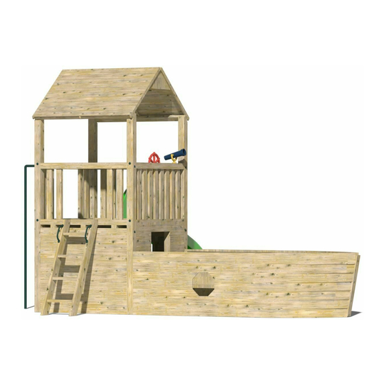
- Page 1 Titanic Climbing Frame Instruction Manual...
- Page 2 Parts List Item Description Image Quantity Number 3m post cut at 40° angle Wall for 4 (2 large, enclosed 2 small, bottom one of each with opening) 3m Tongue and Groove Board...
- Page 3 1280mm post 1460mm x 1010 mm roof panel 6” x 1” small board for roof 6” x 1” large board for roof 1460mm x 1460mm base...
- Page 4 1280mm x 3” x 1.5” timber 1460mm 3” x 1.5” timber Railings 4 (Number of open and closed depends on spec) Open Railing Closed Railing...
- Page 5 Decking Approx. screws 200mm Approx. index screws 120mm Approx. screws Set of steps Screw Approx. covers...
- Page 6 1575mm posts Fireman’s Pole or Rock wall (10 rocks standard for 8ft wall) (5ft wall has 5 rock holds) 9ft slide...
- Page 7 6” x 1” x 2400mm board Porthole Template 3” x 1.5” x 40mm 1 bag screws 6x60 screws (if you get the fireman’s pole Other components included: Handgrips, telescope, steering wheel.
- Page 8 Tools needed: • Cordless drill • Handsaw • Spirit Level • Hammer • Shovel • Stepladder • Pencil • Measuring tape • 10mm Hex bit • PZ 2 Drill Bit Ground Preparation 1. Lay out the base and slide in the position that you intend the climbing frame to be placed. Ensure the base is parallel of any buildings, fences etc.
- Page 9 Assembly Instructions All components needed during the assembly are numbered with reference to the parts list, please refer back to the parts list to ensure you are assembling the correct components for each step. Step 1: ‘H-Frame’ Assembly • Lay 2 3m posts that are cut at a 40° angle on a level surface •...
- Page 10 Step 3: • Make a mark 2400mm (2.4m) from the top of both 3m posts. If your frame has a picnic or sandpit picnic table, add a second mark to each post 2100mm down from the top of the post •...
- Page 11 Step 4: • Place another 1460mm 3” x 1.5” timber on the 40° angle on the top of the post and screw into place using the 65mm decking screws • Steps 3 and 4 strengthen the H-frame structure, without this additional support at the top and bottom, the frame will twist once it is lifted up Step 5: •...
- Page 12 Step 6: (Requires heavy lifting, please use at least 2 people) • Lift both ‘H’-frames into the holes that have been cut out in the ground • Make sure the ‘H’-frames are orientated correctly (to ensure that the roof will be able to rest on the tops) Step 7: •...
- Page 13 Step 8: Base Assembly • The structure should now be able to stand on its own • Lift the base and place it onto the two horizontal posts. The 3” x 1.5” base supports should sit onto the horizontal posts •...
- Page 14 Step 9: Railings Assembly • There are 4 railings per tower. The open ones are for the rope bridge, steps, fireman’s pole, monkey bars and slide; the closed ones are for the rock wall, cargo net and swing module. Ensure to fit the railings in their correct positions depending on the desired layout of the frame.
- Page 15 • For the two sides with 4” x 4” posts with the 3” x 1.5” base supports sitting on them, the decking screws should be screwed in from beneath at an angle between each of the 3” x 1.5” base supports Step 10: •...
- Page 16 Step 11: • Repeat steps 9 and 10 for each railing...
- Page 17 Step 12: Roof Assembly • Place one of the 1460mm x 1010mm roof panels directly onto the ground (so that the shingled part is facing downwards) • Using the ‘v’ boards provided assemble the two roof panels together using decking screws...
- Page 18 Step 13: • Lift the roof onto the climbing frame and ensure it is positioned evenly on all sides before securing the roof to the top of the post using 2 x decking screws for each 2” x 1” support of the roof panel •...
- Page 19 Step 14: Enclosed Bottom Step 1 • Place the two small enclosed walls between the 3m posts and below the 1280mm post. The front of the wall should sit flush against these posts. Place the wall with the opening in the desired position (think where the pirate ship will be) •...
- Page 20 Step 15: Remove H-Frame Supports from Tower • Remove H-Frame supports (that were added during steps 3 & 7) so that the other two walls of the enclosed bottom can be fitted...
- Page 21 Step 16: Enclosed Bottom Step 2 • Place the two large enclosed walls between the 3m posts and below the base. The front of the wall should sit flush against these posts. Place the wall with the opening in the desired position (think where the pirate ship will be) •...
- Page 23 Step 17: Setting the posts for the bow of the ship • Using the three 1575mm 90mm x 90mm posts provided place them in the position that they will ultimately be in. The front post will measure 2.7m from the outside of the tower posts and be directly in the centre.
- Page 24 • You are now ready to dig the three holes and recess them into the ground by some 12” • Postcrete these posts into their place, taking care to get the angle of the bow correct, ensuring the T@G won’t be too short. •...
- Page 26 Step 18: Fireman’s Pole Assembly / Rock Wall Assembly • Place the fireman’s pole into its position and mark the position that it will go into the ground, which will be the centre of the railing and out the same distance as the turn in the pole itself •...
- Page 27 • The rock wall is typically made slightly longer than required to allow for a slope • Place the rock wall against the top of a closed railing • Measure the amount you may have to take off the bottom of the rock wall •...
- Page 28 Step 19: Steps Assembly • The steps might have to be cut or dug into place (depending on the slope of your surface) • They are secured using decking screws through the top and sides of the steps into the base of the tower.
- Page 30 Step 20: Slide Assembly • Using 2 decking screws, secure the slide to the bottom timber of an open railing through the pre-drilled holes in the slide...
- Page 32 Step 21: Pirate Ship Assembly Step 2 • Cut in half a piece of the 1460mm 3” x 1.5” and trim these to 770mm • Using decking screws, secure these to the 3m posts, the 770mm 3” x 1.5” shouldn’t be flush to the outside of the 3m posts, it needs to be set 12mm inside to ensure there is enough room for the tongue and groove panels of the ship...
- Page 33 Step 22: Pirate Ship Assembly Step 3 • Before completing this step, ensure that the postcrete used for the posts for the pirate ship has dried! • You should start the cladding from the bottom and work up. Please take care to ensure that the tongue and groove cladding is completely level •...
- Page 35 Step 23: Pirate Ship Assembly Step 4 • Cut four more pieces of 770mm x 3” x 1.5” and secure two to each side of the inside of the ship. Leave enough space between the piece of timber secured to the tower post and these new pieces of 770mm 3”...
- Page 36 Step 24: Pirate Ship Assembly Step 5 • Using the remaining 1460mm 3” x 1.5” to make two benches, one on each side of the ship • This can be done in a number of different ways. For each bench you will need roughly 3 pieces of timber for the seat, 6 pieces for the vertical supports (3 at each end), and 2 pieces (1 at each end) to connect the vertical supports to the horizontal pieces of timber for the seats.
- Page 37 • Secure the horizontal pieces of timber for the seat to the vertical seat posts at the end using decking screws. These pieces of timber may have to be cut at an angle to make them flush with the tongue and groove boards...
- Page 39 Step 25: Pirate Ship Assembly Step 6 • Cut out an octagonal porthole on each side of the ship using the porthole template. This should be cut out between the two pieces of 770mm x 3” x 1.5” that were assembled during step 23...
- Page 40 Step 26: Pirate Ship Assembly Step 7 • Cut out a piece of the 6” x 1” x 2400mm board to fit on the front of the bow post and secure it to the post using decking screws...
- Page 41 Step 27: Pirate Ship Assembly Step 8 • Use the 3m 3” x 1.5” to cover the top piece of tongue and groove of the ship. You will have to cut these pieces in order to achieve the bend. Its recommended to cut a piece to go from the tower to the first 1575mm post and then another to go from the first 1575mm post to the bow post (this needs to be done for both sides of the ship)
- Page 42 Step 28: Concreting structure • Using postcrete and following the manufacturer’s instructions, concrete all the posts into the ground that haven’t already been concreted • The frame should be left overnight before it is used to ensure the postcrete has dried...
- Page 43 The final stage is to put on the accessories, give everything a good sand down to avoid the children getting splinters from any rough edges. All screws should also be checked to ensure they are flush to the surface they are securing. Press the screw covers into the 32mm holes on the posts.
- Page 44 Maintaining Your Climbing Frame My climbing frame has been installed, what do I do next? A: If your climbing frame was installed in a grassed area the installers have concreted the frame into the ground. They have left a small exposed hole, where the posts have been sunk into the ground. The reason this has been done is to allow the concrete to set overnight.
Need help?
Do you have a question about the Titanic and is the answer not in the manual?
Questions and answers