
Related Manuals for HSD ES327


Summary of Contents for HSD ES327
- Page 1 M E C H A T R O N I C S O L U T I O N S Translation of the original instructions ES327, ES330, ES331, ES332, ES370 Electrospindle Assembly instructions Edition.Revision 2.3 H5801H0084 ENGLISH Serial number...
- Page 3 This manual has been prepared for use by customers only, and contains information protected by copyright. It must not be photocopied or reproduced in any form, either fully or in part, without the prior written consent of the manufacturer. HSD S.p.A. © - H5801H0084.fm100713...
- Page 4 Information about the publication HSD S.p.A. © - H5801H0084.fm100713...
-
Page 5: Table Of Contents
Risks associated with the use of the product ..............10 Product Information ......................12 Glossary ........................... 13 Warranty ........................... 14 Technical Specifications Main parts ES327 ......................15 Air-cooled ES330 main parts ................... 17 Liquid-cooled ES330 main parts ..................19 ES331 Main parts ......................21 ES332 Main parts ......................23 ES370 Main parts ...................... - Page 6 Shaft kit replacement ....................... 96 Encoder reader ES370 replacement ................97 Replacement and adjustment of the sensor unit .............. 98 Disposal of the product Troubleshooting List of spare parts Customer service 12.1 Customer service ......................119 HSD S.p.A. © - H5801H0084TOC.fm100713...
-
Page 7: Preliminary Information
In order to prevent incorrect operation that could constitute a hazard for personnel and/or cause damage to the product, all the documents supplied must be read and fully understood. HSD (or its representative), from here on the manufacturer, cannot be held responsible or legally liable for any damage resulting from incorrect use of the documentation. -
Page 8: Symbols Used In The Manual
Check that all the documents listed above are present on delivery of the product. If necessary, further copies can be obtained on request from the manufacturer. Any enclosures. These contain additional information that completes and/or replaces the information in the document with which they are enclosed. HSD S.p.A. © - 0101h03a.fm100713... - Page 9 DÉCLARE QUE LA QUASI-MAC HINE (2006/42/CE ANNEXE IIB) / DECLARA QUE LA CASI MÁQUINA (2006/42/CE A DJUNTO IIB): Matricola / Serial Number / Seriennummer / Numéro de série / Número de serie: Codice HSD / HSD Code / Codice Cliente / Customer Code HSD / Code HSD / Code / Kunden-Code / Code Código HSD:...
-
Page 10: Risks Associated With The Use Of The Product
The operator must be provided with Personal Protection Equipment (PPE) as provided for by current legislation. Loose bulky clothing and accessories (ties, wide sleeves, etc.) must not be worn. HSD S.p.A. © - 0101h03a.fm100713... - Page 11 The product has been analysed in compliance with Directive 2006/42/EC in order to identify possible risk sources. The risks that remain (residual risks) and the relative countermeasures are highlighted in the relative sections of this manual. HSD S.p.A. © - 0101h03a.fm100713...
-
Page 12: Product Information
The product user is responsible for ensuring that the serial number remains intact. The position of the product serial number is shown in chapter 2 “Technical Specifications” An adhesive is applied to the product bearing the address of the registered offices of the manufacturer. HSD S.p.A. © - 0101h03a.fm100713... -
Page 13: Glossary
Abbreviated to S6, followed by the percentage ratio between the period of operation under load and the duration of one cycle. For example: S6 40% (40% operating time under load, 60% operating time without load) (standard CEI EN 60034-1) HSD S.p.A. © - 0101h03a.fm100713... -
Page 14: Warranty
The maintenance is carried out by means of programmed adjustments, repairs, part replacements, etc.. Warranty For information about the warranty, please refer to the documentation issued on purchase of the machine. HSD S.p.A. © - 0101h03a.fm100713... -
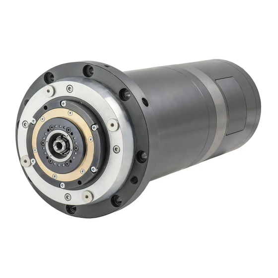
Page 15: Technical Specifications
2 Technical Specifications Technical Specifications Main parts ES327 HSD S.p.A. © - 0102h00a.fm100713... - Page 16 2 Technical Specifications Power/signal wiring outlet Sensor compartment cover Electrospindle casing (joining area) Labyrinth with pressurisation Collet HSK E25 Spindle shaft Front flange Casing (sensors area) Serial number Pneumatic cylinder area Pneumatic and hydraulic joins HSD S.p.A. © - 0102h00a.fm100713...
-
Page 17: Air-Cooled Es330 Main Parts
2 Technical Specifications Air-cooled ES330 main parts HSD S.p.A. © - 0102h00a.fm100713... - Page 18 Power wiring outlet- cable clamp M25x1.5 Signal wiring outlet- cable clamp M16x1.5 Electric flying female connector (“flying mounting plate”) EC plate Fixed male electronic connector (“fixed mounting plate”) Button for tool release manual command Serial number Casing Shaft HSD S.p.A. © - 0102h00a.fm100713...
-
Page 19: Liquid-Cooled Es330 Main Parts
2 Technical Specifications Liquid-cooled ES330 main parts HSD S.p.A. © - 0102h00a.fm100713... - Page 20 Power/signal wiring outlet- n. 2 cable clamps (1xM12 + 1x) Sensor compartment cover Electrospindle "nose" Labyrinth with pressurisation Coupling system ISO30 Spindle shaft Front flange Serial number Casing Pneumatic cylinder area Pneumatic and hydraulic joins HSD S.p.A. © - 0102h00a.fm100713...
-
Page 21: Es331 Main Parts
2 Technical Specifications ES331 Main parts HSD S.p.A. © - 0102h00a.fm100713... - Page 22 Power/signal wiring outlet- n. 2 cable clamps (1xM12 + 1x) Sensor compartment cover Electrospindle "nose" Labyrinth with pressurisation Coupling system ISO30 Spindle shaft Front flange Casing (sensors area) Electrospindle casing Pneumatic cylinder area Pneumatic and hydraulic joins Serial number HSD S.p.A. © - 0102h00a.fm100713...
-
Page 23: Es332 Main Parts
2 Technical Specifications ES332 Main parts HSD S.p.A. © - 0102h00a.fm100713... - Page 24 Pneumatic cylinder area Electrospindle "nose" Labyrinth with pressurisation ISO coupling system Power wiring outlet Sensor wiring outlet Pneumatic and hydraulic joins Encoder wiring outlet Front flange EC plate Serial number Nozzles for external coolant (Optional) Fixing holes HSD S.p.A. © - 0102h00a.fm100713...
-
Page 25: Es370 Main Parts
2 Technical Specifications ES370 Main parts HSD S.p.A. © - 0102h00a.fm100713... - Page 26 Helicoidal casing to optimise cooling Electrospindle "nose" Labyrinth with pressurisation Stator cable outlet (electrospindle power) No. 2 of 3 Or seats for the hydraulic seal of the cooling cylinder liner Serial number Front flange Spindle shaft Tool coupling system HSD S.p.A. © - 0102h00a.fm100713...
-
Page 27: Characteristics And Performance
Rated current 16.8 15.6 Rated efficiency Power factor cos Number of poles Insulation class Cooling Liquid Weight IP level The maximum rated current "S1/cont" is used to set the "maximum continuous current" parameter of the inverter. HSD S.p.A. © - 0102h00a.fm100713... - Page 28 Rotor resistance (20°C) 0.236 P1138 Stator dispersion reactance 0.708 P1139 Rotor dispersion reactance 1.53 P1140 Main field reactance P1141 Field weakening start speed 29200 P1142 Motor moment of inertia 0.000153 P1117 Connection Y or D HSD S.p.A. © - 0102h00a.fm100713...
- Page 29 Rated current Rated efficiency 0.68 Power factor cos 0.68 Number of poles Insulation class Cooling Liquid Weight IP level The maximum rated current "S1/cont" is used to set the "maximum continuous current" parameter of the inverter. HSD S.p.A. © - 0102h00a.fm100713...
- Page 30 Rotor resistance (20°C) 0.682 P1138 Stator dispersion reactance 2.05 P1139 Rotor dispersion reactance 4.48 P1140 Main field reactance P1141 Field weakening start speed 28900 P1142 Motor moment of inertia 0.000153 P1117 Connection Y or D HSD S.p.A. © - 0102h00a.fm100713...
-
Page 31: Rated Power Kw
11.5 Rated efficiency 0.85 Power factor cos Number of poles Insulation class Cooling Electric fan Weight IP level The maximum rated current "S1/cont" is used to set the "maximum continuous current" parameter of the inverter. HSD S.p.A. © - 0102h00a.fm100713... - Page 32 No-load current Stator resistance (20°C) 0.51 Rotor resistance (20°C) 0.67 Stator dispersion reactance Rotor dispersion reactance Main field reactance 49.2 Field weakening start speed 12000 Maximum motor speed 24000 Power factor Connection Y or D HSD S.p.A. © - 0102h00a.fm100713...
-
Page 33: Rated Torque Nm
11.5 Rated efficiency 0.85 Power factor cos Number of poles Insulation class Cooling Electric fan Weight IP level The maximum rated current "S1/cont" is used to set the "maximum continuous current" parameter of the inverter. HSD S.p.A. © - 0102h00a.fm100713... - Page 34 No-load current Stator resistance (20°C) 0.14 Rotor resistance (20°C) 0.17 Stator dispersion reactance Rotor dispersion reactance Main field reactance 14.9 Field weakening start speed 12000 Maximum motor speed 24000 Power factor Connection Y or D HSD S.p.A. © - 0102h00a.fm100713...
- Page 35 12.5 10.8 Rated efficiency 0.85 Power factor cos Number of poles Insulation class Cooling Liquid Weight IP level The maximum rated current "S1/cont" is used to set the "maximum continuous current" parameter of the inverter. HSD S.p.A. © - 0102h00a.fm100713...
- Page 36 No-load current Stator resistance (20°C) 0.51 Rotor resistance (20°C) 0.67 Stator dispersion reactance Rotor dispersion reactance Main field reactance 49.2 Field weakening start speed 12000 Maximum motor speed 24000 Power factor Connection Y or D HSD S.p.A. © - 0102h00a.fm100713...
-
Page 37: Cooling Liquid
16.5 20.1 18.9 Rated efficiency 0.86 Power factor cos 0,78 Number of poles Insulation class Cooling Liquid Weight The maximum rated current "S1/cont" is used to set the "maximum continuous current" parameter of the inverter. HSD S.p.A. © - 0102h00a.fm100713... - Page 38 Rotor dispersion reactance Rotor dispersion inductance 0.45 Main field reactance 13.5 Main field inductance Field weakening start speed 18000 Maximum motor speed 24000 Power factor 0.78 Rotor moment of inertia 9.1E-04 Kg m Connection Y or D HSD S.p.A. © - 0102h00a.fm100713...
- Page 39 27.5 27.5 21.5 Rated efficiency 0,88 Power factor cos 0,77 Number of poles Insulation class Cooling Liquid Weight The maximum rated current "S1/cont" is used to set the "maximum continuous current" parameter of the inverter. HSD S.p.A. © - 0102h00a.fm100713...
- Page 40 Rotor dispersion reactance Rotor dispersion inductance 0.18 Main field reactance Main field inductance Field weakening start speed 12000 Maximum motor speed 24000 Power factor 0.77 Rotor moment of inertia 2.6E-03 Kg m Connection Y or D HSD S.p.A. © - 0102h00a.fm100713...
-
Page 41: Weight Kg
15.7 Rated efficiency 0.85 Power factor cos 0,74 Number of poles Insulation class Cooling Liquid Weight IP level The maximum rated current "S1/cont" is used to set the "maximum continuous current" parameter of the inverter. HSD S.p.A. © - 0102h00a.fm100713... - Page 42 No-load current Stator resistance (20°C) Rotor resistance (20°C) 0.32 Stator dispersion reactance Rotor dispersion reactance Main field reactance 35.1 Field weakening start speed 10500 Maximum motor speed 30000 Power factor 0.85 Connection Y or D HSD S.p.A. © - 0102h00a.fm100713...
-
Page 43: Transport, Packing, Unpacking, Storage
The following figure illustrates methods that can be used to lift the case using cables and a forklift. In the case of a forklift, make sure that the centre of gravity of the case is between the forks when lifting. HSD S.p.A. © - 0103h03a.fm100713... -
Page 44: Unpacking
Do not lift the product by grasping the electric fan as this could damage the guard. The expanded foam and plastic wrapping must be disposed of as plastic material. HSD S.p.A. © - 0103h03a.fm100713... -
Page 45: Storage
–5°C ÷ +55°C (23°F ÷ +131°F) Non condensing relative humidity 5% ÷ 55% The maximum storage time for an HSD product is 12 months. For periods longer than 12 months, the product must be inspected by personnel authorised by the manufacturer. - Page 46 3 Transport, packing, unpacking, storage HSD S.p.A. © - 0103h03a.fm100713...
-
Page 47: Installation And Commissioning
Installation must be performed in a sufficiently lit area. Environmental requisites Temperature: from +5 to +40 °C. (41÷104°F) Maximum relative humidity: 50% (at 40°C/104°F). Maximum altitude: 1000 metres a.s.l. (unless agreed otherwise with the customer). HSD S.p.A. © - 0104h03a.fm100713... -
Page 48: Mechanical Connections
The load-bearing structure on which the product is to be mounted must be sufficiently rigid to support the weight and type of machining to be carried out. 4.4.1 Fixing structure for ES327, “liquid” ES330 The electrospindle must be assembled in "clamped" housing. - Page 49 Use the 8 available Ø9.mm through bores for assembly on the machine (ref. 2.5 “ES332 Main parts”). ES370 Use the 12 available Ø6.5 mm through bores for assembly on the machine (ref. 2.6 “ES370 Main parts”). HSD S.p.A. © - 0104h03a.fm100713...
-
Page 50: Es370: Performing Tool Change
O 3 4 bar Corsa totale Total stroke 8 mm 1 Pressurisation air outlet area 2 Exposed area of the screw dowel to be used to open the collet 3 ø 3 Hole air inlet cone cleaning 4 HSD S.p.A. © - 0104h03a.fm100713... -
Page 51: Pneumatic Connections
(approximately every 6/12 months). 1. Main compressed air supply. 2. Pre-filter 5 µm. 3. Oil separator filter 0.1 µm. 4. To the manufacturer's product. HSD S.p.A. © - 0104h03a.fm100713... - Page 52 Air inlet for tool release and cone cleaning 6 bar - 87 PSI Pressurisation air inlet 0.5 bar - 7.2 PSI Air inlet for tool release (ES327 only) 6 bar - 87 PSI Air inlet for pressurisation and cone cleaning (ES331 only) 1 bar - 14 PSI...
- Page 53 4.6.3 Pneumatic connections For exemplary purposes we have provided the pneumatic connection layout in the figures below, which should be created by the user. Figure 2: exemplary pneumatic layout of the ES327 electrospindles 0,5 Bar O 6x4 O 8x6 6 Bar...
- Page 54 Oil separator filter 0.1 µm. Pre-filter 5 µm Mains power supply Continuous flow of pressurisation air Pressurisation air inlet 0.5 bar - 7.3 PSI Pressure regulator with pressure switch calibrated to 0.5 bar THE PROPOSED CIRCUIT IS PURELY EXEMPLARY. HSD S.p.A. © - 0104h03a.fm100713...
- Page 55 Oil separator filter 0.1 µm. Pre-filter 5 µm Mains power supply Continuous flow of pressurisation air Pressurisation air inlet 0.5 bar - 7.3 PSI Pressure regulator with pressure switch calibrated to 0.5 bar THE PROPOSED CIRCUIT IS PURELY EXEMPLARY. HSD S.p.A. © - 0104h03a.fm100713...
- Page 56 The jet of compressed air is active the entire time the collet remains open. Create a hole in the expulsion actuator of the ES370 electrospindles to allow for the passage of compressed air in order to clean the cone during the tool changing phases. HSD S.p.A. © - 0104h03a.fm100713...
-
Page 57: Cooler Specifications And Hydraulic Connections
ARAL SAROL 340 - 2 ÷ 3 % CINCINNATI CINCINNATI CIMCOOL MG 602 - 4 % HENKEL P3 - PREVOX 6710 - 2 ÷ 3 % CASTROL SYNTILO R PLUS - 2 ÷ 3 % HSD S.p.A. © - 0104h03a.fm100713... - Page 58 The following figures illustrate the hydraulic connection points according to the correspondence shown in this table: Motor cooling liquid inlet Motor cooling liquid outlet Oil inlet for front piston Oil inlet for rear piston Figure 6: Hydraulic connection points ES370 ES330L ES327 HSD S.p.A. © - 0104h03a.fm100713...
- Page 59 4 Installation and commissioning ES331 ES332 HSD S.p.A. © - 0104h03a.fm100713...
- Page 60 Oil inlet for tool locking It is not necessary to supply 50 bar constantly for tool locking. When the safety switch has confirmed piston recovery at the upper limit switch, you can reduce the pressure to 10 bar. HSD S.p.A. © - 0104h03a.fm100713...
-
Page 61: Electronic Connections For Models With Electronic Connectors
+24V DC Sensors +24 V DC Button light 4 17 0 V Sensors +24 V DC Button Button OUTPUT Not used Not used 0 V Button and button light from 12 to 22 : Not used HSD S.p.A. © - 0104h03a.fm100713... - Page 62 4 Installation and commissioning 4.8.3 ES331 encoder connector DESCRIPTION 5V Sense Encoder cable screening 4.8.4 ES332 encoder connector DESCRIPTION Encoder cable screening HSD S.p.A. © - 0104h03a.fm100713...
-
Page 63: Electronic Connections For Models With Free Cables
DESCRIPTION ES327 ES330/ES370 ES331/ES332 Blue (couple) Orange (couple) Yellow/green Yellow/green Yellow/green Earth PE W Brown White White Motor phase U Blue Motor phase V Black Black Black Motor phase W AWG14 (ES331) - AWG10 (ES332) HSD S.p.A. © - 0104h03a.fm100713... -
Page 64: 4.10 Sensor Connections
Pink +24 V Pink +24 V Yellow Yellow Grey Output Grey Output Sensor S3 Sensor S4 Black +24 V Black +24 V Blue Blue Output Output Pulse counter Sensor Purple +24 V Orange Beige Output HSD S.p.A. © - 0104h03a.fm100713... - Page 65 (Tool locked) OUTPUT S5 (no tool) 24V CC sensor feed: S1, S2, S5 0V sensor feed: S1, S2, S4, S5 Motor thermal alarm BIMETALLIC N.C. 130°C Motor thermal alarm BIMETALLIC N.C. 130°C OUTPUT S2 (Tool released) HSD S.p.A. © - 0104h03a.fm100713...
- Page 66 4 Installation and commissioning HSD S.p.A. © - 0104h03a.fm100713...
-
Page 67: General Post-Installation Checks
the cone cleaning air must be present during the tool change; the progress of the tool holder cone ejection must be that specified in section 6.5 “Tool holder locking and ejection device”. HSD S.p.A. © - 0105h00a.fm100713... -
Page 68: First Start-Up Checks
The control sensors must intervene according to the logic described in section 6.8. The tool change cycle must only take place with the shaft stopped. with the tool holder inserted and without performing machining operations, perform the preheating cycle described in section 6.3. HSD S.p.A. © - 0105h00a.fm100713... -
Page 69: Operation And Regulation
Only in the case of the first start-up after storage or machine downtime over four months, anticipate the pre-heating cycle by a preliminary phase of 2 minutes at 5000rpm. HSD S.p.A. © - 0106h03a.fm100713... -
Page 70: Electric Fan
The ejection of the tool holder cone HSK E40 / A40 must be about 0.5 mm - 0.6 mm. The ejection of the tool holder cone BT30 must be about 0.5 mm - 0.6 mm. HSD S.p.A. © - 0106h03a.fm100713... - Page 71 6.5.1 Tool holder cone CONE ISO30 HSD SCREW HSK CONE DIN69871 DOWEL DIN69893 0804H0009 CONE ISO30 SCREW DIN69871 DOWEL MAS 403 PT1 CONE ISO30 SCREW DIN69871 DOWEL BT30 HSD S.p.A. © - 0106h03a.fm100713...
- Page 72 The choice of tool holder is a determining factor as regards safety; The tapered surfaces of the tool holder and its housing on the spindle-shaft must be kept extremely clean to allow safe coupling (see section 7 “Programmed maintenance”); HSD S.p.A. © - 0106h03a.fm100713...
-
Page 73: Tool
- compact, short and light tools - precise, with any inserts correctly fitted with a high degree of safety - balanced and symmetrically coupled with the tool holder - with cutting edges near to the rotation axis HSD S.p.A. © - 0106h03a.fm100713... -
Page 74: Procedure To Follow If The Tool Becomes Jammed In The Piece Being Machined
If this procedure is not followed, the tool holder will drag the locking system (collet/screw dowel) with it until the cone is released. After which, the collet will move back violently due to the force exerted by the spring and could cause damage to the screw dowel. HSD S.p.A. © - 0106h03a.fm100713... -
Page 75: Sensors
IMPATTO breakage Sensors 6.8.1 ES327 electrospindle sensors The ES327 electrospindle is fitted with inductive sensors for monitoring its state and a "thermal alarm" for protecting the electric windings. NAME SIGNAL INFORMATION Tool holder cone coupled Collet open - Tool uncoupled "Shaft stopped"... - Page 76 Tool coupled Sensor Motor overheated: Thermal Alarm stop the electrospindle! 6.8.4 ES331 electrospindle sensors The ES331 electrospindle is equipped with inductive sensors to monitor its condition. NAME SIGNAL INFORMATION Tool ejected No tool Tool coupled HSD S.p.A. © - 0106h03a.fm100713...
- Page 77 An imprecise coupling may constitute a serious risk to the operator. 6.8.7 Technical characteristics of inductive sensors Proximity PNP type Normally Open (N.O.) Power supply voltage 10 ÷ 30 V (DC) Maximum load 100 mA No-load absorption < 17 mA Nominal reading distance HSD S.p.A. © - 0106h03a.fm100713...
- Page 78 Electrospindle states and corresponding outputs from inductive sensors The sensor “ON” condition corresponds to an output equal to the power supply voltage. The “OFF” condition corresponds to a 0 V output.. ES327 and ES330 “air” STATE Collet open (tool holder cone ejected)
- Page 79 6 Operation and regulation ES331 DIAGRAM SETTING SENSORS - 0.10 TOOL OUT - 0.10 TOOL IN - 0.10 TOOL IN WITHOUT TOOL CONDITIONS BROWN + WITHOUT TOOL UB10-30V BLACK TOOL IN TOOL OUT PNP NO HSD S.p.A. © - 0106h03a.fm100713...
- Page 80 Tool holder cone locked correctly The electrospindle shaft can only rotate in the "tool holder cone locked correctly" state; if S1 or S1 + S4 output changes to “OFF”, stop the rotation of the electrospindle shaft. HSD S.p.A. © - 0106h03a.fm100713...
- Page 81 CNC. Ignore signal S3 during the tool-change phase as this could randomly appear on one of the two states (“ON” or “OFF”). The S3 signal is not present in any version. HSD S.p.A. © - 0106h03a.fm100713...
- Page 82 This signal must be used by a device which stops the machine to protect the electrospindle. The operation temperature threshold varies according to the type of electrospindle (for further information contact the manufacturer's assistance service). The thermistors used comply with regulations DIN44081-44082. HSD S.p.A. © - 0106h03a.fm100713...
-
Page 83: Encoder (Optional)
(see the figures below).The signals are shown on the outside as illustrated in section “Electronic connections for models with electronic connectors”. There are three encoder models available: "Square Wave" from the manufacturer; Lenord+Bauer "Square Wave"; "Sine" (Lenord+Bauer). HSD S.p.A. © - 0106h03a.fm100713... - Page 84 400 pulses per rotation + zero notch Signal output TTL electrical levels compatible (0V, +5V line driver) A voltage level higher than the one specified (24V ±10%) may damage the encoder reader. Manufacturer's Square Wave encoder signal Period Phase displacement (D=T/4) HSD S.p.A. © - 0106h03a.fm100713...
- Page 85 (256 impulses multiplied x4 internally) Signal output TTL electrical levels compatible (0V, +5V line driver) Lenord+Bauer Square Wave Encoder Signals Period Phase displacement (D=T/4) A voltage level higher than the one specified (5V ±5%) may damage the encoder reader. HSD S.p.A. © - 0106h03a.fm100713...
- Page 86 160mV= 2.34V (see figures below) A voltage level higher than the one specified (5V ±5%) may damage the encoder reader. Trend of signal A over time: A– 360° electrical de- = (A+) – (A–) DIFF HSD S.p.A. © - 0106h03a.fm100713...
- Page 87 6 Operation and regulation Trend of signal B over time: B– 360° electrical de- = (B+) – (B–) DIFF HSD S.p.A. © - 0106h03a.fm100713...
- Page 88 6 Operation and regulation Trend of signal Z over time: 2,75 2,25 2,75 2,25 Z diff= (Z) - (Z-) 0,75 3,25 0,25 2,75 -0,25 2,25 -0,5 -0,75 1,75 HSD S.p.A. © - 0106h03a.fm100713...
- Page 89 6 Operation and regulation Phase displacement of signals A and B 2,75 2,25 Phase displacement of inverted signals A and B 2,75 2,25 HSD S.p.A. © - 0106h03a.fm100713...
- Page 90 6 Operation and regulation Trend of differential signals over time: 0,75 0,25 -0,25 -0,5 -0,75 Period Phase displacement (D=T/4) A diff. (A) - (A-) B diff. (B) - (B-) Z diff. (Z) - (Z-) HSD S.p.A. © - 0106h03a.fm100713...
-
Page 91: Programmed Maintenance
All personnel taking part in the maintenance operations must be in full visual contact with each other in order to be able to signal any dangers that may arise. HSD S.p.A. © - 0107h00a.fm100713... -
Page 92: Daily Maintenance
HSD S.p.A. © - 0107h00a.fm100713... - Page 93 The tool holder to be removed may be hot! Use gloves! HSD S.p.A. © - 0107h00a.fm100713...
-
Page 94: Biweekly Maintenance
• Rinse and dry the product before re-using the tool holder. Bearings Do not touch the bearings as they are permanently lubricated with special high speed grease, and DO NOT NEED THE PERIODIC ADDITION OF GREASE. HSD S.p.A. © - 0107h00a.fm100713... -
Page 95: Replacing Components
Replacement and adjustment operation are only authorised with the original spare parts of the manufacturer described in this section of the manual. Any other type of intervention is not allowed and will invalidate the warranty. HSD S.p.A. © - 0108h02a.fm100713... -
Page 96: Replacing The Electric Fan
The serial number is usually stamped on the front flange or on the front of the casing (see section 2 “Technical Specifications”). The replacement of the shaft kit is only possible for the standard ES370 electrospindle; for ES330 and ES370 electrospindles consult the manufacturer for assistance. HSD S.p.A. © - 0108h02a.fm100713... -
Page 97: Encoder Reader Es370 Replacement
definitively tighten the two fixing screws of the encoder reader, remove the thickness spacer which had previously been inserted, HSD S.p.A. © - 0108h02a.fm100713... -
Page 98: Replacement And Adjustment Of The Sensor Unit
To access the sensor compartment lift the cover after having unscrewed the 4 screws that lock it The adjustment of the sensors in model ES327 occurs by moving the sensor axially in relation to the electrospindle; while with models ES330 and ES370 the adjustment occurs by rotating the sensor unit and taking advantage of the eccentricity of the nut that contains it. - Page 99 “liquid” ES330 Figure 14 SEZIONE A-A S2 sensor S2 S3 sensor S3 S4 sensor S4 SC pulse counter sensor SC screws washer eccentricity between the nut and sensor, for adjustment calibrated position Sensor free cable outlet HSD S.p.A. © - 0108h02a.fm100713...
- Page 100 Sensor free cable outlet ES332 Figure 16 S1 sensor S1 S2 sensor S2 S3 sensor S3 screws washer calibrated position Sensor electric connector Slot with clearance Calibration movement HSD S.p.A. © - 0108h02a.fm100713...
- Page 101 8 Replacing components ES370 Figure 17 S1 sensor S1 S4 sensor S4 screws washer eccentricity between the nut and sensor, for adjustment calibrated position Sensor electric connector HSD S.p.A. © - 0108h02a.fm100713...
- Page 102 ES327 Figure 18 +24 V Out S1 Out S2 Out S3 “air” ES330 Figure 19 +24 V Out S1 Out S2 “liquid” ES330 Figure 20 +24 V Out S2 Out S3 Out S4 Out SC HSD S.p.A. © - 0108h02a.fm100713...
- Page 103 +24 V Out S2 Out S3 Out S4 ES332 Figure 22 +24 V Out S1 Out S4 Out S2 Out S5 ES370 Figure 23 +24 V Out S1 Out S1+S4 +24 V Brown Blue Output Black HSD S.p.A. © - 0108h02a.fm100713...
- Page 104 8. adjust the sensor unit, so as to obtain the outputs required in the paragraphs immediately below; tighten the screw “1” locking the sensor unit, so as to maintain the performed calibration. HSD S.p.A. © - 0108h02a.fm100713...
- Page 105 12. if the table is not verified, repeat the procedure from the beginning; 13. if the table is verified, make the machine perform a cycle of 100 tool changes, using the largest possible number of different tool holders; HSD S.p.A. © - 0108h02a.fm100713...
- Page 106 14. at the end of the cycle check that the table at point (11) is satisfied: if so the adjustment procedure of S1 is finished; if not repeat the procedure from the beginning. The sensors of the electrospindle ES327 are regulated by axially moving the sensor instead of rotating it.
- Page 107 9. at the end of the cycle, check that the table shown in point (2) has been satisfied for the entire 360° rotation of the shaft. Otherwise repeat the procedure from the start; 10. If the table in point (2) is satisfied, the calibration of S4 is complete. HSD S.p.A. © - 0108h02a.fm100713...
- Page 108 The gauges and spacers described in figure are identified by their thicknesses engraved on the surface or listed on the label of the pack. HSD S.p.A. © - 0108h02a.fm100713...
- Page 109 360° rotation of the shaft. Otherwise repeat the procedure from the start; 10. If the table in point (2) is satisfied, the calibration of S1 is complete. The sensors of the electrospindle ES327 are regulated by axially moving the sensor instead of rotating it.
- Page 110 1. verify that the signal provided by the sensor corresponds to that described in section 6.8.7; 2. if not, rotate the sensor until the position necessary to obtain the output described in the table is found 6.8.7; 3. fully tighten the screw “2”. HSD S.p.A. © - 0108h02a.fm100713...
-
Page 111: Disposal Of The Product
The different materials, such as electric motors (copper windings), metal components, plastic materials, lubricants, liquid coolants, etc. must be sorted and separated then disposed of in accordance with the laws applicable in the country of installation . HSD S.p.A. © - 0109h03a.fm100713... - Page 112 9 Disposal of the product HSD S.p.A. © - 0109h03a.fm100713...
-
Page 113: 10 Troubleshooting
Replace the defective sensor as described in section 8.4 “Replacement and adjustment of the sensor unit”. Rotation denied: Consult the manuals or the suppliers of the machine, the numerical control and the inverter that is connected to the electrospindle. HSD S.p.A. © - 0110h00a.fm100713... - Page 114 Regulate the sensor as described in section 8.4 “Replacement and adjustment of the sensor unit”. Replace the defective sensor as described in section 8.4 “Replacement and adjustment of the sensor unit”. HSD S.p.A. © - 0110h00a.fm100713...
- Page 115 (in the paragraph relating to your model). Machining is too Lighten the machining. heavy: Fixing screws loose: Tighten the fixing screws: Bearings damaged: Contact the manufacturer's assistance service. Bearings noisy: Bearings damaged: Contact the manufacturer's assistance service. HSD S.p.A. © - 0110h00a.fm100713...
- Page 116 10 Troubleshooting HSD S.p.A. © - 0110h00a.fm100713...
-
Page 117: 11 List Of Spare Parts
H5664H0057 Sensor S3 H5664H0058 Sensor S4 H5638H0016 Movable connector collection ES332 H5664H0019 Sensor S1 H5664H0082 Sensor S2 H5664H0083 Sensor S4 H5664H0084 Sensor S5 H3811H0402 HSK E40 -F50 gauge kit for regulating sensors S1 and S4 HSD S.p.A. © - 0111h02a.fm100713... - Page 118 Sensor and encoder movable connectors 2147A0404 Connector join 2450A3847 Flat jet 2450A3902 Stackable segment 1/4’’ 2450A3940 1/8’’ gas join ES370 H5664H0048 S1 or S4 Sensor H3811H0402 HSK E40 -F50 gauge kit for regulating sensors S1 and S4 HSD S.p.A. © - 0111h02a.fm100713...
-
Page 119: 12.1 Customer Service
Loc. Chiusa di Ginestreto factory headquarters: P.le Alfio De Simoni, sn 61122 PESARO (ITALY) Tel. (+39) 0721.205.211 (+39) 0721.205.247 E-mail supporthsd@hsd.it www.hsd.it HSD Deutschland GmbH Brückenstrasse, 32 D-73037 Göppingen Tel. +49(0)7161 956660 +49(0)7161 9566610 E-mail supporthsddeut@hsddeutschland.de www.hsddeutschland.de HSD S.p.A. © - 0112k03a.fm100713... - Page 120 (+1) 954 587 1991 (+1) 954 587 8338 E-mail supporthsdusa@hsd.it www.hsdusa.com HSD Mechatronic Shanghai Co. Ltd. D2, First floor, 207 Taigu road Waigaoqiao Free Trade Zone 200131, Shanghai – China Phone no. (+86) 215866 1236 E-mail sales@hsd-china.cn www.hsd-china.cn HSD S.p.A. © - 0112k03a.fm100713...
- Page 122 HSD NEL MONDO HSD WORLDWIDE M E C H A T R O N I C S O L U T I O N S HSD S.p.A. HSD USA Inc. HSD Deutschland GmbH HSD Mechatronic Sede centrale: 3764 SW, 30th Avenue Brückenstrasse, 32...
Need help?
Do you have a question about the ES327 and is the answer not in the manual?
Questions and answers