Advertisement
Table of Contents
- 1 Table of Contents
- 2 Instructions for Correct and Safe Use of the Radio Control Device
- 3 Installation of the Radio Control Device
- 4 Arrangement and Description of Controls
- 5 Inspection of the Radio Control Device
- 6 Keeping the Radio Control Device in Good Working Order
- 7 Changing the Battery
- 8 Changing the Transmitter
- 9 Programming the Radio Control Device
- 10 Diagnostics
- 11 Operating Principle
- 12 Identification of the Fuses
- 13 Technical Characteristics
- 14 Guarantee Conditions
- Download this manual
Advertisement
Table of Contents

Related Manuals for REMdevice t3


Summary of Contents for REMdevice t3
- Page 1 INSTRUCTION MANUAL RADIO CONTROL DEVICES REMdevice S.r.l. NEW! Via Andrea Mantegna, 12/14 36061 Bassano del Grappa (VI) REMsys CODE Italy Tel. +39 0424 500 262 Patented system Fax +39 0424 508 631 www.remdevice.com E-mail: info@remdevice.com...
-
Page 2: Table Of Contents
Instruction Manual Radio control devices T3, T5 and T7. version 1.4 Genn. 10 SUMMARY • Instructions for correct and safe use of the radio control device ................3 • Installation of the radio control device ......7 • Arrangement and description of controls ...... 10 •... -
Page 3: Instructions For Correct And Safe Use Of The Radio Control Device
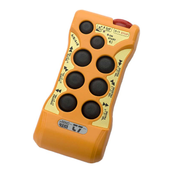
Instruction Manual Radio control devices T3, T5 and T7. version 1.4 Genn. 10 INSTRUCTIONS FOR CORRECT AND SAFE USE OF THE RADIO CONTROL DEVICE The use of the radio control device is reserved to expert operators who have read the instructions on the conditions of use of the radio controlled machine and who respect the safety regulations imposed by law in the work area. - Page 4 Instruction Manual Radio control devices T3, T5 and T7. version 1.4 Genn. 10 Transmitter T3 Transmitter T5 Transmitter T7 STOP/EMERGENCY RED LED BUTTON BATTERY GREEN LED GREEN LED AUX FUNCTION (ON) START BUTTON BUTTON CONTROL CONTROL BUTTONS BUTTONS Figure 1 ®...
- Page 5 Instruction Manual Radio control devices T3, T5 and T7. version 1.4 Genn. 10 Activation 1- Turn and release the Stop/Emergency button (Figure 1): power is supplied to the transmitter. 2- Press the START button. Activation is indicated by the blinking of the green led (ON) at intervals of about 1 second.
- Page 6 Instruction Manual Radio control devices T3, T5 and T7. version 1.4 Genn. 10 Self cut-out When this function is activated (factory setting), the transmitter switches off automatically after 3 minutes of inactivity. It is restarted when the START button is pressed.
-
Page 7: Installation Of The Radio Control Device
Radio control devices T3, T5 and T7. version 1.4 Genn. 10 INSTALLATION OF THE RADIO CONTROL DEVICE REMdevice is at the disposal of installation technicians to supply useful information that will ensure the correct installation and commissioning of the radio control device. - Page 8 Instruction Manual Radio control devices T3, T5 and T7. version 1.4 Genn. 10 Two receiver models are available: ECOBOX watertight receiver for outdoor use • Ruby-T7 watertight receiver for outdoor use • Rx-DIN T7 DIN receiver for indoor use with external aerial •...
- Page 9 Instruction Manual Radio control devices T3, T5 and T7. version 1.4 Genn. 10 The Ruby-T7 receiver must not be positioned inside screened metal structures (boxes, cupboards, trellises, tubes, grids, etc.), so as not to jeopardise the reception of the radio signal; it must be installed with the entry of the multicore cable facing down, so as to avoid water infiltrations through the cable clamp.
-
Page 10: Arrangement And Description Of Controls
Instruction Manual Radio control devices T3, T5 and T7. version 1.4 Genn. 10 Arrangement of controls ECOBOX Receiver LED PLL CONTROL RELAY OUTPUTS CONNECTOR SUPPLY CONNECTOR POWER SUPPLY STOP/EMERGENCY FUSE RELAY FUSE Figure 5 ® device page 10 of 28... - Page 11 Instruction Manual Radio control devices T3, T5 and T7. version 1.4 Genn. 10 Arrangement of controls in the receiver ECOBOX CR13 CR13 CR13 COM-2 COM-2 COM-1 COM-1 START START STOP STOP V-ALIM V-ALIM V-ALIM V-ALIM CR13 CR11 CR13 START COM-2...
- Page 12 Instruction Manual Radio control devices T3, T5 and T7. version 1.4 Genn. 10 Ruby T7 Receiver FUNCTION CHANGE WIRE JUMPERS MONITOR TESTER CONNECTOR LED PLL LED LINK COMMANDS COMANDI CONTROL LED ON RELAY OUTPUTS CONNECTOR COMUNI COMMON B-NC B-COM B-NA...
- Page 13 Instruction Manual Radio control devices T3, T5 and T7. version 1.4 Genn. 10 Arrangement of controls in the receiver Ruby T7 B-NC B-COM B-NA A-NC A-COM A-NA V-ALIM Figure 8 V-ALIM V-ALIM = Receiver power supply STOP = Stop/Emergency Contact (N.C. with transmitter active) START= Start Contact (N.A.)
- Page 14 Instruction Manual Radio control devices T3, T5 and T7. version 1.4 Genn. 10 Rx DIN T7 Receiver COMMAND RELAY AND POWER SUPPLY CONTACTS AERIAL CONNECTOR POWER SUPPLY FUSE FUNCTION CHANGE WIRE JUMPERS LED PLL LED LINK MONITOR TESTER LED ON...
- Page 15 Instruction Manual Radio control devices T3, T5 and T7. version 1.4 Genn. 10 Arrangement of controls in the receiver Rx-DIN T7 STOP V-ALIM STOP V-ALIM START START CLAX CLAX LAMP LAMP ABIL ABIL CR10 CR10 CR11 CR12 CR12 CR13 CR10...
-
Page 16: Inspection Of The Radio Control Device
Instruction Manual Radio control devices T3, T5 and T7. version 1.4 Genn. 10 INSPECTION OF THE RADIO CONTROL DEVICE With the operating machine turned off, insert the plug of the multicore cable of the receiver in place of that of the wired pushbutton panel and secure it with the fastening hooks;... -
Page 17: Keeping The Radio Control Device In Good Working Order
Instruction Manual Radio control devices T3, T5 and T7. version 1.4 Genn. 10 KEEPING THE RADIO CONTROL DEVICE IN GOOD WORKING ORDER Clean the transmitter periodically to prevent the accumulation over time of dirt which is difficult to remove and may cover the graphic symbols on the control buttons. -
Page 18: Changing The Battery
Instruction Manual Radio control devices T3, T5 and T7. version 1.4 Genn. 10 CHANGING THE BATTERY Remove the 8 closing screws and open the transmitter cover. Take out the battery connector and replace it with a new one. Close the cover and retighten the closing screws. -
Page 19: Changing The Transmitter
Instruction Manual Radio control devices T3, T5 and T7. version 1.4 Genn. 10 CHANGING THE TRANSMITTER In the event of malfunction, breakage or loss of the transmitter, it is possible to replace it with a new one. The programming of the code involves only the transmitter, while the receiver is combined and tuned automatically, thanks to the exclusive new patented “REMSYS CODE”... -
Page 20: Programming The Radio Control Device
Instruction Manual Radio control devices T3, T5 and T7. version 1.4 Genn. 10 PROGRAMMING RADIO CONTROL DEVICE Changing the frequency The operation of changing frequency is carried out only on the transmitter, the receiver is tuned automatically. RED LED • Release... - Page 21 Instruction Manual Radio control devices T3, T5 and T7. version 1.4 Genn. 10 Attention: the frequency changing operation must be carried out with the transmitter programmed in medium or normal power operating mode, this operation is not possible if the “low power start”...
- Page 22 Instruction Manual Radio control devices T3, T5 and T7. version 1.4 Genn. 10 Programming the transmitter functions It is possible to programme the following functions: 1 - Self cut-out 2 -Radio frequency output power 3 - Enabling of AUXILIARY 7 button (relay CR13)
- Page 23 Instruction Manual Radio control devices T3, T5 and T7. version 1.4 Genn. 10 Change of receiver functions Operate on the “FUNCTION CHANGE” wire jumpers inside the receiver. RECEIVER OPERATION Wire Jumper Frequency change blocked. The last frequency set becomes the working frequency and can no longer be changed.
-
Page 24: Diagnostics
Instruction Manual Radio control devices T3, T5 and T7. version 1.4 Genn. 10 DIAGNOSTICS If the radio-controlled machine is not working correctly, it is necessary to understand whether the problem depends on the machine or on the radio control device. -
Page 25: Operating Principle
Instruction Manual Radio control devices T3, T5 and T7. version 1.4 Genn. 10 OPERATING PRINCIPLE Description of the Transmitter The commands given with the buttons are processed by the microprocessor which constructs the coupling telegram including the univocal code and sends it to the radio transmission module. -
Page 26: Identification Of The Fuses
Instruction Manual Radio control devices T3, T5 and T7. version 1.4 Genn. 10 Description of the coupling telegram The telegram has a constant length, composed of 144 bits: • 48 bits are dedicated to the start line; • 48 bits are assigned to the coupling address between receiver and transmitter;... -
Page 27: Technical Characteristics
Instruction Manual Radio control devices T3, T5 and T7. version 1.4 Genn. 10 TECHNICAL CHARACTERISTICS Parameters of the Radio Control device - Operative frequency available in the following ranges: 869.700 – 870.000 MHz/ Channelling pitch 25 kHz/ N° channels 11 433.050 –... -
Page 28: Guarantee Conditions
REMdevice declines any responsibility in the event of any errors and omissions. REMdevice reserves the right to alter the specifications described at any time and without prior notice. It is forbidden to reproduce, transmit, transcribe or store the...
Need help?
Do you have a question about the t3 and is the answer not in the manual?
Questions and answers