Table of Contents
Advertisement
PRINTED IN USA
P/N 990-30168
MAINTENANCE MANUAL
OWNER: _________________________________________________________________________
_________________________________________________________________________
_________________________________________________________________________
SOLD AND SERVICED BY: _________________________________________________________
MODEL NO. ___________________________ SERIAL NO. ______________________________
OPERATION AND
IC-35-2F
_________________________________________________________
_________________________________________________________
COPYRIGHT 2011
BRODERSON MFG. CORP.
Courtesy of Crane.Market
Advertisement
Table of Contents

Related Manuals for Broderson IC-35-2F


Summary of Contents for Broderson IC-35-2F
- Page 1 PRINTED IN USA COPYRIGHT 2011 P/N 990-30168 BRODERSON MFG. CORP. OPERATION AND MAINTENANCE MANUAL IC-35-2F OWNER: _________________________________________________________________________ _________________________________________________________________________ _________________________________________________________________________ SOLD AND SERVICED BY: _________________________________________________________ _________________________________________________________ _________________________________________________________ MODEL NO. ___________________________ SERIAL NO. ______________________________ Courtesy of Crane.Market...
- Page 2 STATEMENT OF WARRANTY FOR MOBILE CRANES Broderson Manufacturing Corp. ("BMC") warrants its products to be free from defects in material or workmanship at the date of shipment from BMC. This warranty shall be effective only when validated by the return to BMC of it’s standard form of Warranty...
- Page 3 IC-35-2F Operation and Maintenance Manual Addendum for Drum Rotation Indicator Drum Rotation Indication (DRI) is a new feature added to Broderson Manufacturing Corp. cranes shipped after November 1, 2011. The following information in bold is supplemental to the Operation and Maintenance Manual.
-
Page 4: Table Of Contents
Normal Gauge Readings……….…………………… 2-7 Rated Capacity Limiter……………………………… 2-8 Crane Capacity………..…………………………………… 2-9 Crane Capacity Example……...………………...… 2-11 Crane Capacity Chart IC-35-2F………….…………2-12 Crane Capacity Chart IC-35-2F Metric………….… 2-12M Sheave Block and Downhaul………...…………………… 2-13 Two-Part-Line Reeving……….…………………………… 2-14 Safety Devices………...…………………………………… 2-15 Optional Equipment Operation………...………………… 2-16 Boom Extension……...………………………………2-16... - Page 5 SECTION 3 MAINTENANCE (cont'd) Hydraulic System Maintenance………...………………… 3-17 Purging the Hydraulic System……….……………… 3-21 Bleeding the Brakes……..…………...………………3-23 Hydraulic Seals………..……………………………… 3-24 Hydraulic System Adjustments………….…………………3-25 Control Valves………..……………………………… 3-25 Boom Cylinder Holding Valve………..……………… 3-26 Extension Cylinder Holding Valve………..…………3-26 Engine Maintenance………..…………………………… 3-27 Air Cleaner Service……...…………………………… 3-27 Cooling System………..………………………………...
-
Page 6: Introduction
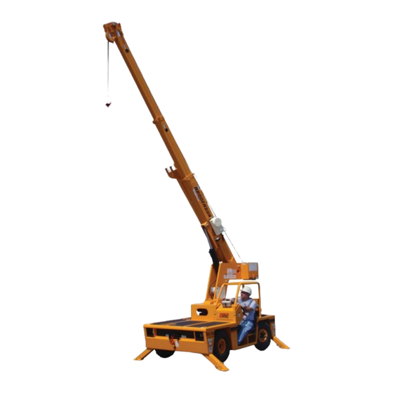
BRODERSON MANUFACTURING CORP. IC-35 INDUSTRIAL CRANE INTRODUCTION The Broderson IC-35 was designed and built to provide safe, dependable and efficient crane service. This we assure by our testing and quality control procedures. properly utilize the full potential of the equipment, the following customer controlled conditions must exist: 1. -
Page 7: Dimensions And Orientation Ic-35-2F
DIMENSIONS AND ORIENTATION IC-35-2F Courtesy of Crane.Market... -
Page 8: Turning Dimensions
TURNING DIMENSIONS Courtesy of Crane.Market... -
Page 9: Description And Specifications
SECTION 1 DESCRIPTION AND SPECIFICATIONS BMC’s IC-35-2F is a self-propelled industrial crane designed for in-plant lifting and material handling applications. It has the special features of low height, narrow width, short length, cargo deck, rear wheel steer, and front wheel drive. The basic unit consists of a chassis and hydraulic boom assembly. - Page 10 Weight Distribution: Front Axle: 3780 pounds (1715 kg) Rear Axle: 4080 pounds (1850 kg) Total 7860 pounds (3565 kg) Tire Footprint Area: 46 square inches (297 cm ), each Outrigger Footprint Area: 48 square inches (310 cm ), each Drawbar Pull: 2120 pounds (960 kg) Gradeability: 30% (1)
- Page 11 Engine: Standard Gasoline: GM 2.4L, Woodward EFI Dual Fuel, EPA Tier II Certified: Industrial gasoline engine complete with multi-port electronic fuel injection, dual fuel, and engine management system. Water-cooled, 4-cylinder, 147 CID (2.4 L), 3.44-inch (87.4 mm) bore, 3.94-inch (100 mm) stroke, 65 HP (48 kW) at governed speed of 2500 rpm.
- Page 12 Brakes: Standard: Primary braking from hydrostatic transmission. Foot-actuated disc brake attached to each torque hub for additional braking in some conditions. Parking brake switch locks brakes to hold crane when not being driven. Tires: Standard: 7.50 x 10 pneumatic tires, 16 ply. Pressurized to 150 psi (1000 kPa) for crane rated loads.
- Page 13 Headlight and Taillight Grilles: Consists of welded steel protective grilles for headlights and taillights. Easily removes or swings out of way for replacing bulbs. Optional Chassis Accessories: Auxiliary Winch: Optional worm gear winch mounted behind front bumper, with a single lever control at the operator’s console.
- Page 14 Operator Guard: Tubular steel weldment with heavy expanded steel mesh top bolts over operator’s compartment. Net Weight: 60 pounds (27 kg) Operator Guard Cover: Vinyl cover with windows to go over operator guard for inclement weather operations. Net Weight: 12 pounds (6 kg) Floormat: Ribbed vinyl mat with foam backing for operator comfort.
- Page 15 Hydraulic System: Standard: Tandem pump mounted to rear end of hydrostatic piston pump which is driven by the engine crankshaft. Delivers 6 gpm (23 L/min) at 2,600 psi (179 bar) for boom circuits and 17 gpm (64 L/min) at 2,250 psi (155 bar) for hoist circuit.
- Page 16 Rated Capacity Limiter: Operator's aid that warns operator of impending overload with audible and visual signals. Has read-outs for load, boom angle, boom length and load radius. In the event of an overload, dumps the following boom functions: HOIST RAISE, TELESCOPE EXTEND, BOOM LOWER, SWING LEFT, and SWING RIGHT.
- Page 17 Courtesy of Crane.Market...
-
Page 18: Operation
OPERATION SAFETY RULES GENERAL: 1. Since the manufacturer has no direct control over machine application and operation, conformance with good safety practice is the responsibility of the user and his operating personnel. 3. The operator shall be responsible for those operations under direct... - Page 19 LIFTING: 1. Always refer to Crane Capacity Chart in operator's compartment before handling load. Do not exceed load ratings. Under some conditions the standard capacity ratings cannot be recommended and must be adjusted downward to compensate for special hazards, such as weak supporting ground, wind, hazardous surroundings, operator inexperience, etc.
- Page 20 14. Be sure at least five wraps of rope are left on the hoist drum to insure against rope pulling out of its anchor. 15. Never wrap the hoist rope around a load. Always use approved rigging. 16. Avoid pinch points such as between a rotating turret and the cab or operator guard or in access holes of a telescop- ing boom.
- Page 21 TRAVEL: 1. For Pick and Carry operation: Traveling with suspended loads involves so many variables, such as ground conditions, boom length and vehicle acceleration, that it is impossible to devise a single standard rating procedure with any assurance of safety. For such operations, the user must evaluate prevailing conditions and determine safe practices using precautions, such as the following: A.
-
Page 22: Instruments And Controls
OPERATION INSTRUMENTS AND CONTROLS The Broderson IC-35 instrument panel is equipped with a standard instrument package showing electrical system amperage, fuel level, oil pressure, water temperature, hydraulic oil temperature, and engine hours. Also included is a bubble level to level the machine. -
Page 23: Sequence Of Operation
Telescope: Pulling back on the lever will retract the boom; pushing forward will extend the boom. Hoist: Pulling back on the lever will raise the hook; pushing forward will lower the hook. Outriggers: The four outriggers may be operated simultaneously or individually. Special attention must be given to avoid hitting personnel or obstacles. -
Page 24: Operating The Crane
On level surfaces the brake pedal is not required for normal stopping. On slopes the operator may have to coordinate the brake and the accelerator to make smooth starts and stops. Emergency stops can be made more quickly by stepping on the brake pedal. This combines hydrostatic braking with the action of the disc brakes. -
Page 25: Rated Capacity Limiter
Fuel - Do not allow fuel tank to become empty. The engine will be difficult to restart and may require "bleeding" of diesel injectors. Keep tank full when idle to prevent conden- sation in tank. W A R N I N G Vapors can be formed inside a fuel tank and cause a buildup of pressure that can result in a sudden expulsion of gasoline and gasoline vapors from the filler neck when the fuel cap is removed from a hot tank. -
Page 26: Crane Capacity
There is a light on the dashboard to warn that one or more outriggers is not fullyextended when using the “On Outriggers” setup on the RCL. Check the light daily when the outriggers are down and there is no load on the hook by raising and lowering each outrigger about three inches. - Page 27 W A R N I N G The Rated Capacity Limiter can suddenly stop the BOOM LOWER and SWING functions, causing the load to bounce or swing. Use great care when handing a load near capacity limits or near a two-blocking condition. CRANE CAPACITY CHART DEFINITIONS AND RULES: The load radius is the horizontal distance from the centerline of boom rotation (the center of the turntable when it is level), to the vertical load line with the load suspended.
- Page 28 CAPACITY EXAMPLE Refer to the IC-35-2F Capacity Chart on the following page. A load weighing 4500 pounds (2040 kg) is to be lifted onto the deck of the crane for transport to a new location.
-
Page 29: Crane Capacity Chart Ic-35-2F
CRANE CAPACITY CHART FOR IC-35-2F 2-12 Courtesy of Crane.Market... -
Page 30: Crane Capacity Chart Ic-35-2F Metric
CRANE CAPACITY CHART FOR IC-35-2F METRIC 2-12M Courtesy of Crane.Market... - Page 31 Courtesy of Crane.Market...
-
Page 32: Sheave Block And Downhaul
SHEAVE BLOCK AND DOWNHAUL WEIGHT The capacity chart shows the approved hoist rope arrangements. The downhaul weight and sheave blocks supplied by Broderson are specially designed to operate the anti-two- block system. Other blocks or downhauls may bypass this system and create a dangerous condition. -
Page 33: Two-Part-Line Reeving
TWO-PART LINE REEVING When resting the downhaul or sheave block on the ground for changing it, use the following procedure to prevent fouling the load line on the hoist. Raise the boom about 5 feet (1.52 m) and lower the hoist until the hook nearly touches the ground. Then lay the hook on the ground by lowering the boom, not the hoist. -
Page 34: Safety Devices
SAFETY DEVICES There are safety devices on the IC-35 to maintain control of a load in case of power or hydraulic line failure or human error. The operator should understand the function and operation of these devices so that a continual check on their performance can be made. OUTRIGGER CYLINDER CHECK VALVE: A double-acting check valve is flange-mounted on each of the outrigger cylinders. -
Page 35: Optional Equipment Operation
HOIST BRAKE AND HOLDING VALVE: The hoist has an automatic brake in the gearbox and a holding valve mounted directly on the hoist motor to hold the load. A clutch in the gearbox allows the winch to turn freely in the RAISE direction. The brake is pilot released in the LOWER direction and should allow smooth stops of a load on the hoist. -
Page 36: Front Auxiliary Winch
STOWING THE BOOM EXTENSION: Reverse the procedure described in steps 7 through 14 in the installation procedure above. Lay the load line back in the tip sheaves and insert both retainer pins and cotters. Replace all of the pins in their lugs for storage and insert their cotters. FRONT AUXILIARY WINCH: The front auxiliary winch is mounted behind the front bumper and is controlled from the operator compartment. -
Page 37: Switch And Indicator Symbols On Bmc Cranes
SWITCH AND INDICATOR SYMBOLS ON BMC CRANES The following list shows the symbols used to label switches and indicators on BMC cranes. Most symbols are derived from the ISO 3767-1:1998(E) standard. Not all symbols will be included on your BMC crane. On/Start Windshield washer switch Off/Stop... - Page 38 Tire pressure Engine oil pressure low Lift point Engine coolant fill location Engine coolant Tie-down point temperature high Engine coolant low level Transmission oil fill location mark Engine air filter restriction Transmission oil pressure indicator Transmission oil Engine start temperature Brake fluid fill location Engine idle set Hydraulic oil low-level mark...
- Page 39 Courtesy of Crane.Market...
-
Page 40: Maintenance
MAINTENANCE SAFETY RULES Lower load and boom, shutdown engine, remove key and put it in a safe place. Place warnings on the ignition switch and crane controls to prevent unauthorized starting or movement during maintenance. Disconnect battery when disabling crane or when welding on crane. Relieve hydraulic pressure when working on hydraulic parts by cycling the controls with the engine shut down. - Page 41 Use a hoist when lifting components that weigh 50 pounds (23 kg) or more. Follow all hoist and rigging safety rules. Do not use lower grade fasteners if replacements are necessary. When reinstalling wiring or plumbing after repairs, be sure that it will not be damaged by rubbing against sharp, rough or hot surfaces or edges.
- Page 42 MAINTENANCE The Broderson IC-35 Industrial Crane will perform better and longer if a program of inspection, lubrication, adjustment and general preventive maintenance is followed. We recommend the following schedule: NEW UNIT INSPECTION AND TEST The following inspection and test should be made before placing the unit on the job.
- Page 43 OPERATOR INSPECTION AND TEST An operator, in the course of normal operation, should make certain observations, inspections and tests to assure that the unit is ready and able to perform safely. Daily: 1. Check radiator coolant level. 2. Check engine oil level. 3.
-
Page 44: Ic-35 Maintenance Checklist
IC-35 MAINTENANCE CHECKLIST Refer to the component maintenance section of this manual and to the engine operator's manual for complete instructions. 50 HOUR INTERVAL: 1. 50 hour lubrication as shown on lube schedule. 2. Inspect wire rope thoroughly. 3. Inspect for physical damage and leaks. 4. - Page 45 1000 HOUR INTERVAL: 1. 50, 250 and 500 hour maintenance. 2. 50, 250, 500 and 1000 hour lubrication. 3. Adjust engine valve clearance per engine manual. 4. Check and adjust engine speed. 5. Perform engine maintenance specified in engine manual. 6.
-
Page 46: Lubrication
ROTATION BEARING LUBRICATION There is one grease zerk in a hole on the right-hand side of the turntable base plate. This should be used to lubricate the bearing every 50 hours. Rotate the turntable about 45 degrees and pump some grease into the zerk. Repeat until the turntable has rotated two revolutions. - Page 47 IC-35 LUBRICATION CHART Courtesy of Crane.Market...
- Page 48 IC-35 LUBRICATION SCHEDULE LUBRICATION INTERVALS ITEM DESCRIPTION LUBE 1000 MONTHS NOTES SYMBOL HOUR HOUR HOUR HOUR Accelerator Linkage 2 Points (Not on E.F.I.) Anti-Two-Block Arm 2 Points Axle Kingpins 4 Zerks Axle Pivot Pin 1 Zerk Axle Planetary Hubs Check @50, Change @12 Mo.* Boom Extension Pins 6 Pins - Wipe Boom Rub Pads...
-
Page 49: Hoist Cable Installation And Inspection
HOIST CABLE INSTALLATION AND INSPECTION The following steps will assure that the wire rope winds smoothly and evenly on the hoist and will yield greater safety and longer cable life: 1. If possible, the cable should be rolled off a storage spool and straightened out on the ground in line with the boom. - Page 50 Slowly rotate the hoist while applying tension on the cable in front of the boom. Wear heavy leather gloves and wrap rags around the cable to wipe off any dirt from the cable. Keep hands away from the sheaves and hoist drum while the cable is moving.
-
Page 51: Jic Schematic
JIC SCHEMATIC 3-12 Courtesy of Crane.Market... -
Page 52: Jic Schematic Metric
JIC SCHEMATIC METRIC 3-12M Courtesy of Crane.Market... - Page 53 Courtesy of Crane.Market...
-
Page 54: Steering System
HYDRAULIC SYSTEM The IC-35 hydraulic system consists of three subsystems, driven by a triple pump. The 34 gpm (129 L/min) piston pump powers the propulsion system. The 6 gpm (23 L/min) gear pump supplies the hydrostatic steering function and the boom and outrigger functions. - Page 55 STEERING SYSTEM 3-14 Courtesy of Crane.Market...
-
Page 56: Propulsion System
PROPULSION SYSTEM The propulsion system is a closed-loop hydrostatic transmission. The variable volume piston pump is driveline driven from the engine crankshaft. The pump can deliver up to 34 gpm (129 L/min) or 4,000 psi (276 bar) to the wheel drive motors. The flow from the wheel drive motors returns directly to the pump inlet, not the reservoir. - Page 57 IC-35 PROPULSION SYSTEM 3-16 Courtesy of Crane.Market...
- Page 58 START-UP PROCEDURE -- PISTON PUMP When initially starting a new or rebuilt transmission pump, it is extremely important that the start-up procedure be followed. It prevents damaging the unit that might occur if the system is not properly purged and charged with oil before start-up. 1.
- Page 59 6. After the system shows signs of filling, run it in neutral and low idle for 5 minutes. Then extend the outriggers so that drive wheels can spin freely. Reconnect the brake release valve if disconnected in step 3. Place the control switch in the "FORWARD"...
- Page 60 IC-35 PISTON PUMP TROUBLESHOOTING TROUBLE CAUSES REMEDIES 1. System will A. Brake switch tripped Release brake switch. not operate B. Oil supply low Check oil level, fill. in either C. Oil filter clogged Replace filter element. direction. D. Oil too heavy Use proper viscosity oil.
-
Page 61: Care Of Hydraulic Oil
CARE OF HYDRAULIC OIL The hydraulic system contains many highly pressurized, precision components. protect these, it is very important to keep the hydraulic oil clean, at proper temperature, within the oil specification and to the proper fill level. The IC-35 is equipped with a 100-mesh suction strainer, a 10-micron suction filter, a breather filter, a 10-micron, return-line filter and a 14 gallon (53 L) tank. -
Page 62: Purging The Hydraulic System
APPROVED HYDRAULIC FLUIDS WARM CLIMATE: COOL CLIMATE: MOBIL ATF D/M* MOBIL MULTI-VEHICLE ATF MOBIL MULTI-VEHICLE ATF DEXRON VI DEXRON VI * Mobil ATF D/M was used at the factory to fill the hydraulic system of your IC-35. C A U T I O N Never add kerosene or other "thinners"... - Page 63 Clean the reservoir and strainer and replace the filter elements and hoses, except the return hose at the inlet of the smaller filter and the case drain hose at the hydrostatic pump. Attach a 3/4" I.D. return hose at the hydrostatic pump case drain port and run it into a waste oil sump or barrel.
-
Page 64: Bleeding The Brakes
Position the crane so that the boom may later be fully topped up, rotated and extended. Do not operate these functions until the proper step. Close the small gate valve in the return line and disconnect the return hose from the return filter inlet again. -
Page 65: Hydraulic Seals
HYDRAULIC SEALS W A R N I N G Do not check for hydraulic leaks with hands. If a mist of hydraulic oil is noticed around a line or component, use cardboard or other material to check for location of leak. High pressure fluid leaking from a small hole, can be almost invisible, yet have enough force to penetrate the skin. - Page 66 CONTROL VALVE ADJUSTMENTS The crane control valve has two relief valves to protect the hydraulic components. The relief valves are adjustable and should be checked and set as follows: 1. Boom and outrigger circuits 2,600 psi (179 bar) at full flow. 2.
-
Page 67: Boom Cylinder Holding Valve
(not the hoist). An example of rated load for the IC-35-2F is 4,150 pounds (1830 kg) at an 8 foot (2.5 m) load radius, with outriggers extended and the boom over the front. Turn the engine off and move the "BOOM" lever to the "LOWER"... -
Page 68: Engine Maintenance
ENGINE MAINTENANCE AIR CLEANER SERVICE: Clean out the dust cup every 50 hours. Loosen the clamps around the cup and housing and remove the cup. Dump dust out of cup. Clean gasket and sealing surfaces with a damp cloth. Replace cup gasket if it shows signs of damage. Replace cup with arrows pointing up and tighten clamp. -
Page 69: Mechanical Adjustments
MECHANICAL ADJUSTMENTS FASTENERS: All fasteners in the IC-35 should be checked, and retightened if required, as a part of the preventive maintenance program. Particular attention should be given to the axle, wheel and hub mounting bolts, pump mounting bolts, rotation bearing bolts, rotation gearbox bolts and hoist bolts. -
Page 70: Torque Data
TORQUE DATA BOLT SAE GRADE SAE GRADE SAE GRADE GRADE 1 OR 2 MARKING MEDIUM CARBON MEDIUM CARBON MATERIAL LOW CARBON STEEL ALLOY STEEL Q & T Q & T MINIMUM TENSILE 64,000 PSI 120,000 PSI 150,000 PSI STRENGTH (441 MPa) (827 MPa) (1034 MPa) BOLT SIZE... - Page 71 Courtesy of Crane.Market...
Need help?
Do you have a question about the IC-35-2F and is the answer not in the manual?
Questions and answers