Table of Contents
Advertisement
Quick Links
Centrometal d.o.o. - Glavna 12, 40306 Macinec, Croatia, tel: +385 40 372 600, fax: +385 40 372 611
TECHNICAL INSTRUCTIONS
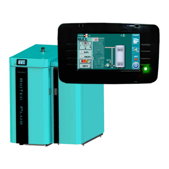
Description and using of BioTec Plus
control unit
- USER
THE FIRST START-UP MUST BE DONE BY AUTHORIZED PERSON
OTHERWISE PRODUCT WARRANTY IS NOT VALID
TUBTP-CU-08-2017-1.08h-ENG
HEATING TECHNIQUE
BioTec Plus
Advertisement
Table of Contents

Related Manuals for Centrometal BioTec Plus


Summary of Contents for Centrometal BioTec Plus
- Page 1 HEATING TECHNIQUE Centrometal d.o.o. - Glavna 12, 40306 Macinec, Croatia, tel: +385 40 372 600, fax: +385 40 372 611 TECHNICAL INSTRUCTIONS Description and using of BioTec Plus control unit - USER THE FIRST START-UP MUST BE DONE BY AUTHORIZED PERSON...
- Page 2 DESCRIPTION SWITCHING ON After turning on the main switch, screen will display language selection menu and software version. To select the language, press the flag of language you want. Software version vx.xx xx kW Boiler power (25, 29, 31, 35, 45 kW) Language selection If the language selection is "disabled"...
- Page 3 RIGHT SIDE TOOLBAR LEGEND: 1 - Time & Date 2 - Display selection - Main menu / Main screen 3 - Button for change fuel (WOOD(w) / PELLETS(p)) 4 - State of the current boiler status (working phase) 5 - Boiler Start / Stop...
- Page 4 MAIN MENU Main menu on BioTec Plus boiler control unit is composed of two parts - changeable part (1a and 1b) and static part (2). By pressing button for change fuel (see image below) displayed parameter will be changed. Displaying parameters can be changed regardless of boiler working phase and which fuel are choosen as active for work.
- Page 5 BUTTONS Button ’’ON / OFF’’ Button ’’OK’’ options: on / off boiler operation’’ Button ’’DISPLAY SELECTION’’ Button ’’START’’/’’STOP’’ options: main menu / work Button ’’BOILER OPERATION DISPLAY’’ Navigation buttons: options: graphic / numeric ’’LEFT’’, ’’RIGHT’’, ’’UP’’, ’’DOWN’’ Button ’’DELETE’’ Button ’’ENTER’’ Button ’’BACK’’...
-
Page 6: Main Screen
MAIN SCREEN 13 14 19 20 1a - Boiler (Wood firing side) 11 - Combustion chamber temperature 1b - Boiler (Pellet firing side) 12 - Flue gas temperature 2 - Buffer tank 13 - The percentage of oxygen in the flue gases 3 - Boiler pump P1 (lambda probe) 4 - 3 - way protection valve... - Page 7 SYMBOLS Pump (when pump is working symbol is rotating, otherwise idle) The pump has a request for work (next to the pump symbol bright yellow square when the consumer given the demand for work the pump, the pump does not work if you have not met all the conditions for work, for example.
- Page 8 CHOOSING BOILER SIDE (choosing fuel) Using of BioTec Plus boiler are consist of using of left part of the boiler (fuel: wood) and using of right part of the boiler (fuel: wood pellets). On boiler control unit is necessary to choose which side of the boiler will be used (which fuel will be used).
- Page 9 TAKING OVER Note: Option „Taking over” is possible only from left side of the boiler (fuel: wood) to right side of the boiler (fuel: wood pellets) (wood pellets taking over wood). „Taking over” option is used for automatic switching operation from one fuel to another fuel. Automatic switch is possible only from wood to wood pellets.
- Page 10 PARAMETERS MANAGMENT Methods for parameters input Method 1: entering parameters by Method 2: entering parameters by choosing offered values. numerical keyboard (numerical values). x.x.x. Working phase x.x.x. Working phase Factory: 1 - Working phase bar - on this bar will be showned name of working phase for which changing parameters value 2.
-
Page 11: Boiler Temperature
WOOD(w) MENU 1. TEMPERATURE X - only if „DHW” (domestic hot water) exist on heating system (must be configured like additional equipment) 1.1. (w) BOILER TEMPERATURE In this parameter is possible to adjust boiler working temperature. Possible adjustment: - Factory adjusted: 85°C - Minimal adjustment value: 75°C - Maximal adjustment value: 90°C 1.2. -
Page 12: Dhw Temperature
1.4. (w) DHW TEMPERATURE In this parameter is possible to adjust domestic hot water temperature. Possible adjustment: - Factory adjusted: 50°C - Minimal adjustment value: 40°C - Maximal adjustment value: 80°C 1.5. (w) DIFFERENCE OF DHW TEMPERATURE In this parameter is possible to adjust difference of domestic hot water temperature. - Page 13 2. (w) GLOW In menu "Glow” option for glow maintenance can be turned on or of. Possible selection: - Factory selected: Day temperature - Possible selection: OFF, ON; ENABLED OPTION GLOW: when, on fuel load storage, remain only glow, boiler can maintain remain glow for max 12h, depend about heating requirement.
-
Page 14: Operation
3. OPERATION 3.1. MANUAL TEST 3.1.1. FAN Option for boiler fan testing. Fan can be tested on 1700rpm and max. rpm. When the fan works, fan symbol on display is animated. - Page 15 3.1.2. PRIMARY CLOSE Option for primary air motor device (close direction) test. By pressing „Start” button primary air motor device will be start with closing. 3.1.3. PRIMARY OPEN Option for primary air motor device (open direction) test. By pressing „Start” button primary air motor device will be start with opening.
- Page 16 3.1.6. PUMP P1 Option for P1 pump test. By pressing „Start” button P1 pump will be start with work. When the pump works, pump symbol on display is animated. 3.1.7. ELECTRO-MAGNETIC VALVE Option for electro-magnetic valve test. By pressing „Start” button electromagnetic valve will be start with work.
- Page 17 3.1.10. VALVE CLOSING Option for protection valve (closing) test. By pressing „Start” button protection valve will be start with closing. 3.1.11. VALVE OPENING Option for protection valve (opening) test. By pressing „Start” button protection valve will be start with opening. 3.1.12.
-
Page 18: Chimney Sweeper
3.2. CHIMNEY SWEEPER This option allows the flue gas measurement at boiler nominal power (D6). Possible selection: - Factory selected: Disabled - Possible selection: Disabled, D6 100%;... -
Page 19: Forced Shutdown
3.3. FORCED SHUTDOWN This option is used to forced stop all processes. First must be pressed the ON/OFF button to put the boiler in shutdown procedure and then ''forced shutdown'' button. All processes are stopped. Option ”FORCED SHUTDOWN“ is not usual procedure for turning OFF the boiler IMPORTANT! To be able to stop all processes, you must first turn off... - Page 20 3.4. ALARM This option is used for error report by speaker or lamp to living area. It’s neccessary to buy light or sound alarm „CAL” which can be installed only by authorized person (before using of alarm is neccessary to configure it in „Installation” menu whoose access have only authorized persons by entering PIN).
-
Page 21: Fuel Level
3.4.x.1. ERRORS This parameter determines whether the output 1 errors occur. By selecting certain types of signals will be activated in the selected signal format. Possible selection: - Factory selected: OFF - Possible selection: Off, Continous, Fast 1 time, Fast 3 times, Slow 1 time, Slow 3 time, Table 3.4.x.2. - Page 22 3.4.x.3. BUFFER 3.4.x.3.1. BUFFER This parameter define whether will it output 1 report warning for low temperature in buffer tank. This option don’t allow setting of his own table for signal type in different time of day, but adjusted table for fuel level warning can be used.
- Page 23 3.4.3 TABLE This parameter is used to select the predefined table for the alarm. The automatic switching on and off or changing the signal type at a specific time. It is possible to adjust signal type for speaker and signal type for low fuel level warning.
- Page 24 Below are described all symbols for types of signal. In the same way, you can fill table 2 and table 3. The type of connected device (lamp or speaker) can be set only in installation menu, only by an authorized person. Symbol descriptions (signal types) For fuel level warning (green) For boiler error alarm (red)
-
Page 25: Pump Protection
3.5. PUMP PROTECTION In this parameter is possible to enable /disable pump protection. Possible selection: - Factory selected: OFF - Possible selection: OFF, ON; 3.6. FUEL LEVEL TABLE In this parameter is possible to change used fuel (choosing boiler side for work). Possible selection: - Factory selected: WOOD - Possible selection: WOOD, PELLETS;... - Page 26 3.8.1. SCREW REFILL In this parameter is possible activate option for filling feeder screw. Possible selection: - Factory selected: OFF - Possible selection: OFF, ON; 3.8.2. TIME In this parameter is possible to adjust how long will be work option for feeder screw fill. Possible adjustment: - Factory adjusted: 300 sec - Minimal adjustment value: 0 sec...
- Page 27 PELLETS(p) MENU 1. TEMPERATURE X - only if „DHW” (domestic hot water) exist on heating system (must be configured like additional equipment) 1.1. (p) MAXIMAL BOILER TEMPERATURE In this parameter is possible to adjust maximal boiler working temperature. Possible adjustment: - Factory adjusted: 80°C - Minimal adjustment value: 70°C - Maximal adjustment value: 90°C...
- Page 28 1.4. (p) DIFFERENCE OF BUFFER TANK STOP TEMPERATURE In this parameter is possible to adjust difference of buffer tank stop temperature (condition for boiler shut down and pause). Possible adjustment: - Factory adjusted: 5°C - Minimal adjustment value: 3°C - Maximal adjustment value: 30°C 1.5.
- Page 29 1.8. (p) RETURN FLOW TEMPERATURE In this parameter is possible to adjust return flow temperature. Possible adjustment: - Factory adjusted: 60°C - Minimal adjustment value: 60°C - Maximal adjustment value: 70°C 2. SCHEDULE 2.1. (p)SCHEDULE Possible selection: - Factory selected: OFF (schedule is turned off) - Table 1 - Scheduled starting times are turned-on and work according to the settings in Table 1 - Table 2 - Scheduled starting times are turned-on and work according to the settings in Table 2 - Table 3 - Scheduled starting times are turned-on and work according to the settings in Table 3...
- Page 30 2.2, 2.3, 2.4, (p)TABLE 1,2,3 Possibility of schedule is done using tables They can be pre-set 3 tables of schedule of which only one table can be active It is possible for every day of the week set 3 turning-on and 3 turning-off the boiler.
-
Page 31: Manual Test
3. OPERATION 3.1. MANUAL TEST... - Page 32 3.1.1. FAN Option for boiler fan testing. Fan can be tested on 1700rpm and max. rpm. When the fan works, fan symbol on display is animated. 3.1.2. PRIMARY CLOSE Option for primary air motor device (close direction) test. By pressing „Start” button primary air motor device will be start with closing.
- Page 33 3.1.5. SECONDARY OPEN Option for secondary air motor device (open direction) test. By pressing „Start” button secondary air motor device will be start with opening. 3.1.6. PUMP P1 Option for P1 pump test. By pressing „Start” button P1 pump will be start with work.
-
Page 34: Rotary Valve
3.1.9. ROTARY VALVE Option for backfire protection rotating valve (RSE) test. By pressing „Start” button rotating valve will be start with work. When rotating valve works, rotating valve symbol on display is animated. 3.1.10. ELECTRIC HEATER Option for electric heater test. By pressing „Start”... - Page 35 3.1.13. PUMP P3 Option for P3 pump test. By pressing „Start” button P3 pump will be start with work. When the pump works, pump symbol on display is animated. 3.1.14. VALVE CLOSING Option for protection valve (closing) test. By pressing „Start” button protection valve will be start with closing.
- Page 36 3.1.17. SCREW REFILL Option for pellet feeding system test. By pressing „Start” button pellet feeding system will be start with work. When the pellet feeding system works, pellet feeding system symbol on display is animated.
- Page 37 3.2. CHIMNEY SWEEPER 3.2.1. CHIMNEY SWEEPER This option allows the flue gas measurement. Possible selection: - Factory selected: OFF - Possible selection: OFF, ON; 3.2.2. MINIMAL BOILER TEMPERATURE In this parameter is possible to adjust minimal boiler temperature at flue gas measurement. Possible adjustment: - Factory adjusted: 60°C - Minimal adjustment value: 60°C...
- Page 38 3.2.3. TIME In this parameter is possible to adjust time for flue gas measure. Possible adjustment: - Factory adjusted: 600s - Minimal adjustment value: 600s - Maximal adjustment value: 3600s 3.2.4. POWER In this parameter is possible to adjust boiler power for flue gas measurement.
- Page 39 3.3. FORCED SHUTDOWN This option is used to forced stop all processes. First must be pressed the ON/OFF button to put the boiler in shutdown procedure and then ''forced shutdown'' button. All processes are stopped. Option ”FORCED SHUTDOWN“ is not usual procedure for turning OFF the boiler IMPORTANT! To be able to stop all processes, you must first turn off...
- Page 40 3.4. ALARM This option is used for error report by speaker or lamp to living area. It’s neccessary to buy light or sound alarm „CAL” which can be installed only by authorized person (before using of alarm is neccessary to configure it in „Installation” menu whoose access have only authorized persons by entering PIN).
- Page 41 3.4.x.1. ERRORS This parameter determines whether the output 1 errors occur. By selecting certain types of signals will be activated in the selected signal format. Possible selection: - Factory selected: OFF - Possible selection: Off, Continous, Fast 1 time, Fast 3 times, Slow 1 time, Slow 3 time, Table 3.4.x.2.
- Page 42 3.4.x.3.2. FUEL LEVEL TABLE In this parameter is possible to turn on / off table for fuel level alarm. Possible selection: - Factory selected: OFF - Possible selection: OFF, ON 3.4.x.4. DELAY This parameter define after how long will be again activate error / warning of fuel level / low temperature of buffer tank (this parameter doesn’t work if is selected continous signal).
- Page 43 3.4.3 TABLE This parameter is used to select the predefined table for the alarm. The automatic switching on and off or changing the signal type at a specific time. It is possible to adjust signal type for speaker and signal type for low fuel level warning.
- Page 44 Below are described all symbols for types of signal. In the same way, you can fill table 2 and table 3. The type of connected device (lamp or speaker) can be set only in installation menu, only by an authorized person. Symbol descriptions (signal types) For fuel level warning (green) For boiler error alarm (red)
- Page 45 3.5. PUMP PROTECTION In this parameter is possible to enable /disable pump protection. Possible selection: - Factory selected: OFF - Possible selection: OFF, ON; 3.6. FUEL LEVEL TABLE In this parameter is possible to change used fuel (choosing boiler side for work). Possible selection: - Factory selected: WOOD - Possible selection: WOOD, PELLETS;...
- Page 46 3.8.1. SCREW REFILL In this parameter is possible activate option for filling feeder screw. Possible selection: - Factory selected: OFF - Possible selection: OFF, ON; 3.8.2. TIME In this parameter is possible to adjust how long will be work option for feeder screw fill. Possible adjustment: - Factory adjusted: 300 sec - Minimal adjustment value: 0 sec...
-
Page 47: Maintenance
5. MAINTENANCE 5.1. MANUAL BOILER CLEANING Cleaning the boiler - By pressing the button ’’START’’ (1) fan will begin work (2), an burner grate (3) will move into the open position (100%) (4), (button ’’START’’ will become a button’’STOP’’). This option enables you to during cleaning of combustion chamber, boiler ash does not come out of the boiler, and since the burner grate is open ash falls into the ash box. - Page 48 5. HISTORY By pressing on „History” button will be opened menu for choosing history list. It can be choosen between error list and warning list. Informations history are placed with error list. Written is: - time of occurrence errors/ warnings/ informations - error/warning/information code - description of the error/warning/information.
-
Page 49: Date And Time
7. DATE & TIME By pressing this option on the main screen you can set the date and time. This option is used to set the date and time. It is necessary for starting times, and the recording of errors/warnings/informations (for the occurrence of errors / warnings, remembers the date and time of occurrence). -
Page 50: Software Version
8.2 SOFTWARE VERSION Software version displaying. 9. DISPLAY 9.1 SCREENSAVER Of at some time nothing was pressed on the screen, the screensaver will turn on, to prevent damage on the screen. Once you touch the screen the screensaver will be turned off. Possible adjustment: - Factory adjusted: 600s - Minimal adjustment value: 10s... -
Page 51: Language Selection
9.2 LANGUAGE SELECTION This option enables or disables screen with the choice of language regulation when you turn on main switch. If is marked ''DISABLED'', after turning- on the main switch, it will be set on before selected language and after some time, display will show the work display of the boiler.(The time until this screen appears can be adjusted in point 9.3.). - Page 52 10. FILE 10.1 FILE After pressing ''LOAD FACTORY'' you will see a message ''LOAD FACTORY SETTINGS?''. Pressing button ''OK'' will load the default settings of regulation. Pressing the'' BACK'' will return to the previous menu. 10.2 SAVE After pressing ''SAVE'' you will see a 3 slots to save data (Memory 1, 2, 3).
-
Page 53: Installation
10.3 LOAD After pressing ''LOAD’' you will see ''LOAD SAVED SETTINGS?''. Pressing button ''OK'' saved settings (saved in option SAVE) will be loaded. Pressing the ''BACK'' will return to the previous menu. 11. INSTALLATION This menu can use only authorized persons. For entry in „Installation“... - Page 54 10. REGULATOR Menu „Regulator” is showed only if module for two heating circuits CM2K-B is installed and configurated. 12. MANUAL TEST Menu „Regulator” is showed only if module for two heating circuits CM2K-B is installed and configurated. 12.1.1 1.CIRCUIT Option for testing elements of 1st heating circuit (mixing valve (START-open), mixing valve (START- close) and pump (START)).
- Page 55 12.1.2 2.CIRCUIT Option for testing elements of 1st heating circuit (mixing valve (START-open), mixing valve (START- close) and pump (START)). 12.2 1.CIRCUIT 8.2.2.1. CIRCUIT Option for turning on / off first heating circuit. Possible selection: - Factory selected: ON - Possible selection: ON, OFF;...
-
Page 56: Heating Curve
12.2.2 HEATING CURVE This parameter determine the coefficient of the heating curve. The regulation calculate required flow temperature according to the heating curve and outside temperature to achieve the desired room temperature. Possible adjustment: - Factory adjusted: 1 - Minimal adjustment value: 0,1 - Maximal adjustment value: 4,0 Coefficient Outside temperature... - Page 57 12.2.3 CORRECTION COEFFICIENT. This parameter determines the influence of the room corrector. When this coefficient is larger, room corrector will more affect to the calculated required flow temperature in the heating circuit. Possible adjustment: - Factory adjusted: 1 - Minimal adjustment value: 0,1 - Maximal adjustment value: 5,0 °C 12.2.4 DAY ROOM TEMPERATURE...
- Page 58 12.2.5 NIGHT ROOM TEMPERATURE This parameter determines the value of night room temperature. Possible adjustment: - Factory adjusted: 20,0°C - Minimal adjustment value: 5°C - Maximal adjustment value: 30,0°C 12.2.6 NIGHT ROOM TEMPERATURE This option enables you to choose type of desired temperature (day, night or table.) In next page you can see how to fill a table.
-
Page 59: Transition Time
12.2.7 TABLE 1 Night temperature Day temperature Each cell marks the beginning of some type (day/night) of selected room temperature. According to this table every day from monday at 06:00 am is activated day room temperature, until 22:00 pm when is activated night room temperature until tuesday, when at 06:00 am is again activated day room temperature. - Page 60 Centrometal d.o.o. assumes no responsibility for possible inaccuracies in this book originated typographical errors or rewriting, all the pictures and diagrams are principal and it is necessary to adjust each actual situation on the field, in any case the company reserves the right to enter their own products such modifications as considered necessary.
Need help?
Do you have a question about the BioTec Plus and is the answer not in the manual?
Questions and answers