
Related Manuals for SIGMATEK SCP 011


Summary of Contents for SIGMATEK SCP 011
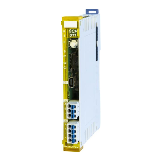
- Page 1 SCP 011 S-DIAS Safety CPU Module Date of creation: 18.12.2013 Version date: 28.02.2020 Article number: 20-890-011-E...
- Page 2 (print, photocopy, microfilm or in any other process) without the express permission. We reserve the right to make changes in the content without notice. The SIGMATEK GmbH & Co KG is not responsible for technical or printing errors in the handbook and assumes no responsibility for damages that occur...
- Page 3 The safety-related SCP 011 is ideal for use in systems with optional modules and interface variables according to Safety System Handbook, see homepage The SCP 011 module alone is already a minimal system of a safety control. In addition, the SCP 011 regulates the synchronized communication with the remote safety modules through safe bus telegrams.
-
Page 4: Table Of Contents
SCP 011 S-DIAS SAFETY CPU MODULE Contents Basic Safety Guidelines ............4 General Information on Safety ............ 4 Further Safety Guidelines ............5 General Requirements ..............6 Safety Conformity ..............10 Functional Safety Standards ............. 10 EU Conformity Declaration ............10 Safety-Relevant Parameters ............ - Page 5 S-DIAS SAFETY CPU MODULE SCP 011 Validation Button ..............22 Explanation of the Individual Sequences ......... 22 6.1.1 Start Sequence ................. 22 6.1.2 Command Selection Sequence ............23 6.1.3 End Sequence .................. 23 6.1.4 Error Sequence ................. 24 Overview of Commands ............. 25 Overview of Module Statuses and Commands ......
-
Page 6: Basic Safety Guidelines
SCP 011 S-DIAS SAFETY CPU MODULE Basic Safety Guidelines General Information on Safety If the safety guidelines are not followed, dangers to personnel can arise that could lead to serious injury or in worst cases, death. In less serious cases, systems and equipment can be damaged. -
Page 7: Further Safety Guidelines
S-DIAS SAFETY CPU MODULE SCP 011 Further Safety Guidelines Warning, dangerous electrical voltage Avertissement d’une tension électrique dangereuse Hot surface warning Avertissement d’une surface chaude Danger for ESD-sensitive components Les signes de danger pour les composants sensibles aux décharges électrostatiques... -
Page 8: General Requirements
Before handling the product belonging to this documentation, Safety Guidelines the operating instructions and safety guidelines must be read. SIGMATEK GmbH & Co KG accepts no liability for damages resulting from non-compliance with the safety guidelines or the relevant regulations. - Page 9 SIGMATEK GmbH & Co KG n'assume aucune responsabilité pour les dommages causés par le non-respect des consignes de sécurité ou du mode d’emploi respectif. La connaissance de consignes de sécurité et le contenu de cette documentation ainsi que le mode d’emploi du système de...
- Page 10 SCP 011 S-DIAS SAFETY CPU MODULE Designated Use The Safety modules are designed for use in safety-oriented applications and meet the required conditions for safety operation in compliance with Performance level e (PL e), in accordance with EN ISO 13849-1/-2 and SIL3 or SIL CL 3 in accordance with EN 62061.
- Page 11 S-DIAS SAFETY CPU MODULE SCP 011 Operator Due Diligence The operator must ensure that • The Safety modules are to be used for their designated purpose only. • The Safety modules are to be operated in error-free, fully functional condition only.
-
Page 12: Safety Conformity
EN ISO 13849-2:2012 EU Conformity Declaration CE Declaration of Conformity The SCP 011 complies with the following European directives: • 2006/42/EG “Directive of the European Parliament and of the Council of 17 May 2006 on Machinery and Change to the Directive 95/16/EC”... -
Page 13: Compatibility
S-DIAS SAFETY CPU MODULE SCP 011 Compatibility The safety-related module SCP 011 is supported with firmware version V334 and build No. 1156 or higher of the Safety Designer. Use of Safe Analog Values (SAFEDINT): If Safe analog values (variables of type SAFEDINT) are transferred and further processed, an SCP011 with Firmware version V344 or higher MUST be used (HW version 1.60). -
Page 14: Technical Data
SCP 011 S-DIAS SAFETY CPU MODULE Technical Data Performance Data Interfaces 1x Safety Interface Program interfaces 1x USB device Bus connection possible Miscellaneous microSD slot Supply voltage +24 V Electrical Requirements 3.2.1 Module Supply (Input) Supply voltage +18-30 V DC, typically +24 V DC... -
Page 15: S-Dias Bus/Safety Supply (Output)
S-DIAS SAFETY CPU MODULE SCP 011 3.2.2 S-DIAS Bus/Safety Supply (Output) Voltage supply in the +5 V +24 V S-DIAS bus in the +12 V +24 V S-DIAS Safety bus (2) (4) (2) (4) max. 0.8 A max. 0.8 A... - Page 16 SCP 011 S-DIAS SAFETY CPU MODULE If the SCP 011 with a firmware version lower than V355 resp. with a Safety number lower than S01.03.01 is integrated with Safety I/O modules in the S-DIAS system (blue moduls), the voltage increase of the +24 V supply of the SCP 011 must not happen...
- Page 17 S-DIAS SAFETY CPU MODULE SCP 011 28.02.2020 Page 15...
-
Page 18: Miscellaneous
SCP 011 S-DIAS SAFETY CPU MODULE Miscellaneous Article number 20-890-011 Hardware version Standard UL 508 (E247993) Approbations UL, cUL, CE Environmental Conditions Storage temperature -20 ... +85 °C Environmental temperature 0 ... +55 °C Humidity 0-95 %, non-condensing Installation altitude above sea... -
Page 19: Mechanical Dimensions
S-DIAS SAFETY CPU MODULE SCP 011 Mechanical Dimensions 28.02.2020 Page 17... -
Page 20: Connector Layout
SCP 011 S-DIAS SAFETY CPU MODULE Connector Layout The connections of the +24 V supply (X3: pin 1 and pin 2) or the GND supply (X3: pin 3 and pin 4) are internally bridged. To supply the module, only one connection to a +24 V pin (pin 1 or pin 2) and a GND pin (pin 3 or pin 4) is required. -
Page 21: Status Leds
S-DIAS SAFETY CPU MODULE SCP 011 Status LEDs The LED display lights continuously to indicate that the in- and outputs are active. green Indicates The time-limited (LED "S" on) operation mode or unlimited time ("S" LED off) operation mode. Module Status... -
Page 22: Applicable Connectors
SCP 011 S-DIAS SAFETY CPU MODULE Applicable Connectors Connectors: X1: USB Type Mini-B (not included in delivery) X2, X3: Connectors with spring terminals (included in delivery) The spring terminals are suitable connecting ultrasonically compacted (ultrasonically welded) strands. Connections: Stripping length/Sleeve length:... -
Page 23: Label Field
S-DIAS SAFETY CPU MODULE SCP 011 Label Field Manufacturer Weidmüller Type MF 10/5 CABUR MC NE WS Weidmüller article number 1854510000 Compatible printer Weidmüller Type Printjet Advanced 230V Weidmüller article number 1324380000 28.02.2020 Page 21... -
Page 24: Validation Button
SCP 011 S-DIAS SAFETY CPU MODULE Validation Button With the validation button S1, several commands as well as the validation can be executed: • Acknowledging an error and exiting the error status • Deleting a configuration from the Safety CPU •... -
Page 25: Command Selection Sequence
S-DIAS SAFETY CPU MODULE SCP 011 6.1.2 Command Selection Sequence After the Start sequence, the desired command is selected. This selection is made with button presses in the following time intervals: Minimum press duration is 200 ms, maximum is approximately 3 seconds; the minimum pause between individual button presses is 200 ms, the maximum is 10 seconds. -
Page 26: Error Sequence
SCP 011 S-DIAS SAFETY CPU MODULE 6.1.4 Error Sequence If an invalid button press occurs, as in the sequences described above, the Error sequence is initiated. LED B indicates this sequence with fast blinking, which lasts for at least 3 seconds. -
Page 27: Overview Of Commands
S-DIAS SAFETY CPU MODULE SCP 011 Overview of Commands The number of button presses corresponds to the number of light pulses in LED B during the End sequence. Commands Number of button LED C1 LED C2 LED C3 presses QUIT_ERROR... - Page 28 SCP 011 S-DIAS SAFETY CPU MODULE Executed Command function Status after command command execution QUIT_ERROR A possible error is cancelled in the Safety CPU SW-RESET *) and all safety modules required by the Safety CPU and the error status is ended.
-
Page 29: Handling The Microsd Card
S-DIAS SAFETY CPU MODULE SCP 011 Handling the microSD Card An SD card can only be written on with the Safety Designer. A detailed description can be found Safety System Handbook (Link: https://www.sigmatek- automation.com/fileadmin/user_upload/downloads/Safety-Systemhandbuch-eng.pdf). A Safety project, which was programmed with the SafetyDesigner, can be stored on an SD card. -
Page 30: Configuring A Safety Cpu With The Sd Card
Only microSD cards that support version 2.0 or higher of the "SDA Physical Layer Specification" (SDA=SD Card Association) can be used. It is recommended to use only the microSD card approved by SIGMATEK. The number of read and write accesses has a significant influence on the service life of the storage medium. - Page 31 SCP 011 Une carte microSD d'une capacité de stockage de 1 Go est disponible chez SIGMATEK sous le numéro d’article 12-630-101. Uniquement les cartes microSD supportant au moins la version 2.0 de la "SDA Spécification de la couche physique" (SDA = SD Card Association) peuvent être utilisées.
-
Page 32: Error Response
SCP 011 S-DIAS SAFETY CPU MODULE Error Response In the event of an error, please consult the chapter "LED Displays", as important information on the runtime status of the system can be derived from the status an error display. Since errors in general are of a complex nature, do not perform a diagnosis based on the LEDs alone (consult the corresponding chapter in the Safety System Handbook as well). -
Page 33: Configuration Distribution Error
S-DIAS SAFETY CPU MODULE SCP 011 During restart, the Safety CPU first runs the POST (Power On Self Test). In the POST, whether the Safety CPU is configured or not is determined. If the Flash memory in the Safety CPU is empty, it changes to the service mode and switches the status LED (ST) to continuously on. -
Page 34: Troubleshooting
SCP 011 S-DIAS SAFETY CPU MODULE Troubleshooting • Check all modules in the system for completeness and Type conformity • Check that all modules are error-free • Check all connector cables • Cancel the error with the QUIT_ERROR command If the Safety CPU remains in the error status after the QUIT_ERROR command has been executed, it must be retested using the SafetyDesigner. -
Page 35: Wiring Guidelines
S-DIAS SAFETY CPU MODULE SCP 011 Wiring Guidelines The input filters, which suppress noise signals, allow operation in harsh environmental conditions. A careful wiring method is also recommended to ensure error-free function. The following installation guidelines should be observed: •... -
Page 36: Mounting
SCP 011 S-DIAS SAFETY CPU MODULE Mounting The S-DIAS modules are designed for installation into the control cabinet. To mount the modules a DIN-rail is required. The DIN rail must establish a conductive connection with the back wall of the control cabinet. The individual S-DIAS modules are mounted on the DIN rail as a block and secured with latches. - Page 37 S-DIAS SAFETY CPU MODULE SCP 011 Recommended minimum distances of the S-DIAS modules to the surrounding components or control cabinet wall: a, b, c … distances in mm (inches) 28.02.2020 Page 35...
-
Page 38: 10 Supported Cycle Times
SCP 011 S-DIAS SAFETY CPU MODULE 10 Supported Cycle Times 10.1 Cycle Times below 1 ms (in µs) x= supported 10.2 Cycle Times equal to or higher than 1 ms (in ms) x= supported x= supported 11 Disposal For the disposal of the product, the respective guidelines, possibly country-specific, must be observed and followed. - Page 39 S-DIAS SAFETY CPU MODULE SCP 011 Documentation Changes Change date Affected Chapter Note page(s) 11.02.2014 5 Connector Layout Changed image 5.2 Applicable Connectors Connection capacity added French notes added 01.04.2014 10 Mounting Text updated 29.04.2014 New photo 3.2 Electrical Requirements Changed table content and added notice below 23.05.2014...
- Page 40 SCP 011 S-DIAS SAFETY CPU MODULE 18.10.2017 5.3 Label Field Added chapter 10 Mounting Graphic replaced 19.06.2018 3.2.1 Module Supply Note UL conditions 20.09.2018 5 Connector Layout Note added 02.04.2019 2.3 Safety-Relevant Correction of the safety-relevant parameters Parameters 3.4 Environmental Conditions...
Need help?
Do you have a question about the SCP 011 and is the answer not in the manual?
Questions and answers