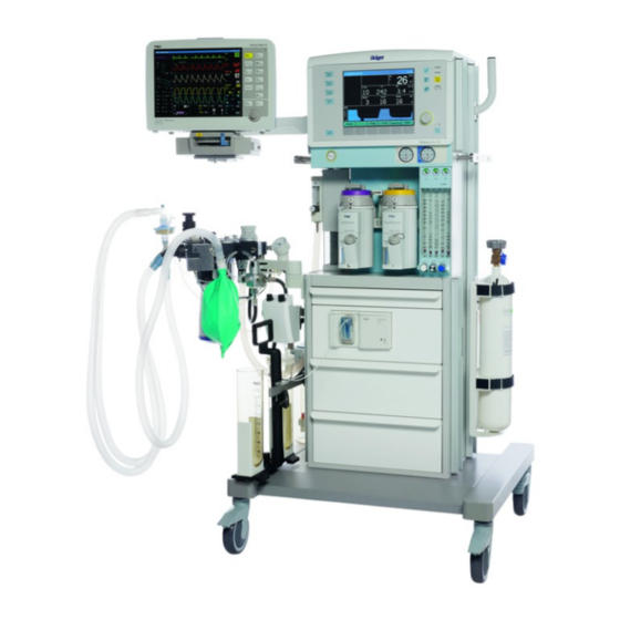
Dräger Fabius plus Instructions For Use Manual
Anesthesia workstation
Hide thumbs
Also See for Fabius plus:
- Instructions for use manual (232 pages) ,
- Supplement manual (49 pages) ,
- Supplement to instructions for use (142 pages)
Table of Contents
Advertisement
Quick Links
Advertisement
Chapters
Table of Contents

Related Manuals for Dräger Fabius plus


Summary of Contents for Dräger Fabius plus
- Page 1 Instructions for Use (only master for IfU zh) Fabius plus Anesthesia Workstation WARNING! For a full understanding of the Software 3.n performance characteristics of this medical device, the user should care- fully read these Instructions for Use before use of the medical device.
-
Page 2: Working With These Instructions For Use
– Dashes indicate the listing of data, options or Turn off fresh gas flow. objects. Instructions for Use Fabius plus SW 3.n Right-Hand Column – the Illustrations The illustrations provide visual reference for the text and for locating the various parts of the equip- ment. -
Page 3: Trademarks
This document is provided for customer information only, and will not be updated or exchanged without customer request. Depending on the configuration of the individual medical device, the images in the Instructions for Use may differ. Instructions for Use Fabius plus SW 3.n... - Page 4 This page intentionally left blank Instructions for Use Fabius plus SW 3.n...
-
Page 5: Table Of Contents
Connecting the Pressure Breathing Gauge..61 Fabius plus as a Wall Device ....23 Connecting the Flow Sensor ....62 Auxiliary Oxygen Flow Meter . - Page 6 Reprocessing Breathing system... . 170 Care List for Fabius plus Components ..172 Reassembling the Breathing System ..174 Reinstalling the Ventilator .
-
Page 7: For Your Safety And That Of Your Patients
Accessories in sterile packaging ... 10 Software ......11 Instructions for Use Fabius plus SW 3.n... -
Page 8: Strictly Follow These Instructions For Use
Follow Assembly Instructions and Instructions for sories be used in conjunction with the specific Use. medical device. Otherwise the correct functio- ning of the medical device may be compro- mised. Instructions for Use Fabius plus SW 3.n... -
Page 9: Patient Safety
The responsibility for the selection of the best level of patient monitoring lies solely with the medical device operator. Instructions for Use Fabius plus SW 3.n... -
Page 10: General Warnings And Cautions
(EMC) and must be installed and put Fabius plus: use a separate wall socket. into operation in accordance with the EMC informa- tion included, see page 195. The system must meet the requirements for... -
Page 11: Software
Any person involved with the setup, opera- If these precautions are not followed, the tion, or maintenance of the Fabius plus anes- device may tip over and pose a risk to safety. thesia workstation must be thoroughly familiar with this instruction manual. - Page 12 NOTE Software must be installed by qualified personnel. CAUTION We recommend to contact DrägerService for soft- Do not use Fabius plus during magnetic reso- ware installation. nance (MRI, NMR, NMI). NOTE Device operation may be affected, thus placing the patient at risk.
-
Page 13: Intended Use
Intended Use ......14 MEDIBUS and Vitalink Protocols ... 14 Instructions for Use Fabius plus SW 3.n... -
Page 14: Intended Use
MEDIBUS and Vitalink Protocols mounted gas cylinders. MEDIBUS and Vitalink are software protocols for Fabius plus is equipped with a compact breathing use in transferring data between the Fabius plus system, providing fresh-gas decoupling, PEEP, and and an external medical or non-medical device pressure limitation. -
Page 15: System Overview
........22 Fabius plus as a Wall Device ... . 23 Auxiliary Oxygen Flow Meter . -
Page 16: Front View
11 Compact Breathing System (COSY) 4 Gauges for central gas supplier 12 Ventilator 5 Flow meters tube block 13 Auxiliary oxygen flowmeter* 6 Fresh-gas control valves 14 Vapor mount 7 Writing table 15 Oxygen Flush optional Instructions for Use Fabius plus SW 3.n... -
Page 17: Compact Breathing System (Top View)
10 Fresh-gas decoupling valve 11 APL bypass valve connection port 12 Breathing system mount with locking bolt 13 Selecting knob for »MAN« and »SPONT« on pressure limiting (APL) valve 14 Sample gas return port optional Instructions for Use Fabius plus SW 3.n... -
Page 18: Rear View (Pin-Index Connector)
1 Connector for cylinders (threaded connectors)* 2 Connectors for medical gas pipeline supply (central supply) 3 Pin index connector for O 4 Pin index connector for N O or AIR* 5 Compact Breathing System (COSY) optional Instructions for Use Fabius plus SW 3.n... -
Page 19: Threaded Connectors
System Overview Threaded Connectors 1 Connector for medical gas pipeline supply (central supply) 2 Connector for cylinders O and N O or O and AIR (threaded connectors)* 3 Cylinders optional Instructions for Use Fabius plus SW 3.n... -
Page 20: Interface Panel
System Overview Interface Panel 1 Potential equalization pin 2 COM 1 3 PEEP 4 APL 5 Oxygen Sensor 6 Pressure Breathing 7 Volume Sensor 8 Power cable connection 9 ON/OFF switch 10 Fuse Instructions for Use Fabius plus SW 3.n... -
Page 21: Vaporizers (Optional)
Note that the selector lever is shown in the center position. This ensures that both vaporizers are in the locked position. Also, this is the recommended position for the selector lever when moving the Fabius plus. Instructions for Use Fabius plus SW 3.n... -
Page 22: Selectatec (Optional)
Extended >10 to Dräger auto exclusion ≤ Operating 15 L/min vaporizer concentration Range output accuracy may be reduced. When using a Desflurane vaporizer, it must be con- nected to mains power. Instructions for Use Fabius plus SW 3.n... -
Page 23: Fabius Plus As A Wall Device
System Overview Fabius plus as a Wall Device* The Fabius plus may also be mounted on the wall. Follow the Assembly Instructions for Fabius plus as a wall device (9037202, 7th edition or higher). Fabius plus uses a holder instead of a trolley, see page 16, to be attached to the wall. -
Page 24: Auxiliary Oxygen Flow Meter
Only then the oxygen flow is completely off. WARNING Risk of fire Before cauterizing, close the flow meter, remove the mask and wait a few moments to ensure that any oxygen accumulation has dis- sipated. optional ASTM F1850-22(2005) §76 Instructions for Use Fabius plus SW 3.n... -
Page 25: Apl Valve
The APL valve is automatically excluded from the breathing circuit whenever an automatic ventila- tion mode is selected. NOTE Even in automatic ventilation, the APL valve must be adjusted to a pressure that is safe for the pati- ent! Instructions for Use Fabius plus SW 3.n... -
Page 26: Communication Ports
System Overview Communication Ports 1 The Fabius plus has one port on the back panel for communication with external devices. The port is labeled COM 1 and supports MEDIBUS and Vitalink communications. WARNING A test for leakage current must be performed... -
Page 27: Auxiliary Fresh-Gas Outlet
There is no monitoring of pressure, volume or for the external fresh-gas outlet. An external monitoring unit must be used to perform the required monitoring of O , CO anesthetic gas, volume and pressure. optional Instructions for Use Fabius plus SW 3.n... -
Page 28: Using The External Fresh-Gas Outlet As A Common Gas Outlet
1 External fresh-gas outlet with an additional switch 2 Long fresh-gas hose (to Fabius) 3 Short fresh-gas hose (on the Compact Brea- thing System, COSY) 4 Compact Breathing System, COSY 5 Sample line 6 Non-rebreathing system (e.g. Bain) optional Instructions for Use Fabius plus SW 3.n... -
Page 29: Accessory Weight Limits
Trolley mounted units: The total combined weight of all accessories and monitors mounted on the CAUTION top and sides of the Fabius plus shall not exceed 80 lb (36 kg). Risk of tip-over and personal injury Front GCX rails have a maximum accessories CAUTION weight load of 5 lb/2.3 kg, extended out at 3 in/... -
Page 30: Abbreviations
Inspiratory Vacuum (e.g. for secretion suction) Insp Flow Inspiratory flow Expiratory minute volume L/min Liters per minute Tidal volume Manual ventilation mbar Millibar MEAN Mean pressure Minute volume Nitrous oxide Oxygen Airway pressure Instructions for Use Fabius plus SW 3.n... -
Page 31: Symbols
Year manufactured External non-rebreathing system XXXX Consult Instructions for Use The following symbols are used on other locations of the Fabius plus to provide quick and easy recog- nition of product functions. Use–by date YYYY-MM Connection for potential equaliza- tion... - Page 32 System Overview The following symbols are used on the Fabius plus monitoring user interface. Upper and Lower Alarm Limits Return to Home Screen Suppress Alarm Tone for Two Minu- Standby Mode Available Operating Capacity of XX % Close Menu, Back to Previous...
-
Page 33: Operation Concept
Gas System Color Coding ....42 Screen Color Concept ....42 Instructions for Use Fabius plus SW 3.n... -
Page 34: Control Panel
Operation Concept Control Panel The control panel on the Fabius plus is character- ized by a small number of elements, clear layout, and ease of operation. Its main elements are: 1 A screen displaying all monitoring and ventila- tion information in numeric and graphic form. -
Page 35: The Screen Display
4 Respiratory volume monitoring window which displays the patient’s respiratory rate in breaths per minute (Freq), tidal volume, minute volume, and the minute volume high and low alarm lim- its. Instructions for Use Fabius plus SW 3.n... -
Page 36: Rotary Knob
SIMV/PS ventilation mode (optional). 4 The »Pressure Support« key is used to select the Pressure Support ventilation mode (optional). 5 The »Pressure Control« key is used to select the Pressure Control ventilation mode. Instructions for Use Fabius plus SW 3.n... -
Page 37: Soft Keys
NOTE The »Volume Alarms On/Off« soft key label does not appear in ManSpont mode because it is select- able on the ManSpont screen. See "Configuration during Operation" on page 143 for complete information. Instructions for Use Fabius plus SW 3.n... -
Page 38: Selecting/Setting Monitoring Functions
»Default Settings« or »Configuration« label. Select and confirm the »Default Settings« label. The Default Settings column is selected. (Selecting and confirming the return arrow will exit the Default Settings column and redisplay the main Setup screen.) Instructions for Use Fabius plus SW 3.n... - Page 39 (For example in the illustration on the right, the alarm limit was changed from 20 to 25.) Confirm the new value for the alarm limit. The new alarm limit is saved and cursor moves to the return arrow. Instructions for Use Fabius plus SW 3.n...
-
Page 40: Selecting/Setting Ventilation Parameters
10 seconds. If the new set- ting is not confirmed within the timeout period, the current ventilation setting remains in effect and the Ventilation Settings window returns to the Wave- form window. Instructions for Use Fabius plus SW 3.n... -
Page 41: Fresh-Gas Control
2 Flow meter tube block (2-gas or 3-gas) O flow control valve 4 AIR flow control valve flow control valve NOTE If the floater is not rotating, the accuracy might be lower than stated in the technical data. Instructions for Use Fabius plus SW 3.n... -
Page 42: Led Indicators
In addition, there are small LEDs on the Standby key and all the ventilation mode keys to indicate the currently active mode. Gas System Color Coding Each control valve and gauge on the Fabius plus is color-coded for the appropriate gas, as shown the table below: Yellow... -
Page 43: Assembly
Sensor ....60 Connecting the Pressure Sensor ..61 Connecting the Pressure Breathing Gauge Instructions for Use Fabius plus SW 3.n... -
Page 44: Activating The Battery
Assembly Activating the Battery The Fabius plus anesthesia workstation is shipped with the battery fuse disconnected in order to pre- vent discharge during shipment and storage prior to installation. Remove the battery fuse from the top drawer of the machine. -
Page 45: Installing The Drägersorb Clic Absorber
– CLIC Absorber Free, or – Infinity ID CLIC Absorber 800+, or – Infinity ID CLIC Absorber Free can be used on the Fabius plus by using the Drägersorb CLIC adapter. For information on installing the Drägersorb CLIC adapter, consult its Instructions for Use. -
Page 46: Connecting The Compact Breathing System
Release the locking bolt and rotate the compact breathing system until the locking bolt locks into position. 3 Connect the fresh-gas hose from the Fabius plus to the compact breathing system. Instructions for Use Fabius plus SW 3.n... -
Page 47: Inserting The Flow Sensor
1 Connect the ventilation hose to the ventilator 2 attach it to the conical connector ventilator port on the compact breathing system. If the Fabius plus is equipped with a threaded con- nector, the sealing rings on the threaded connector must be undamaged and clean. -
Page 48: Connecting The Waste-Gas Outlet Port
Installing the Flexible Bag Arm* or Breathing Bag Extension*and Bag WARNING Risk of use of toxic or incompatible materials Breathing bags used on the Fabius plus must comply with current ANSI standards. CAUTION Risk of unintended perioperative awareness Make sure that during ventilation the bag is tightly connected to the bag arm. -
Page 49: Connecting Pipeline Supply Of N 2 O, Air And O 2
41 and 87 psi (2.8 and 6 kPa x 100). NOTE The loss of the pipeline supply could cause the loss of combined devices. Instructions for Use Fabius plus SW 3.n... -
Page 50: Connecting The Reserve Gas Cylinders
NOTE If cylinder valves are leaky or difficult to open or close, they must be repaired in accordance with the manufacturer’s specifications. optional Instructions for Use Fabius plus SW 3.n... - Page 51 Verify that the washer is in place, the index pins are engaged, and the cyl- inder hangs vertically. Tighten the yoke firmly. Instructions for Use Fabius plus SW 3.n...
- Page 52 (PSI - MIN) should be replaced with new, full cylin- ders. PSI/kPa x 100 - PSI/kPa x 100 - FULL (typical full load) 1900/131 1000/69 745/51 600/42 1900/131 1000/69 Instructions for Use Fabius plus SW 3.n...
-
Page 53: Connecting The Reserve Gas Cylinders For N 2 O, Air And O 2 (For Cylinders With Threaded Connectors)
NOTE The cylinder valves must only be opened or closed manually. Never use tools. NOTE Reserve gas cylinders should remain closed when not in use. Risk of unintentional emptying of cylin- ders. optional Instructions for Use Fabius plus SW 3.n... - Page 54 Screw the pressure regulators onto the cylinder valves. 2 Screw the compressed gas hoses to the pres- sure regulators and to the connections of the gas inlet block. Open the cylinder valves. Instructions for Use Fabius plus SW 3.n...
-
Page 55: Connecting The Ags Anesthetic Gas Receiving System
Assembly Connecting the AGS Anesthetic Gas Receiving System* Every Anesthetic Gas Scavenging System (AGSS) used on the Fabius plus must follow ISO standard 8835-3. The scavenging system is used with vacuum waste-gas disposal systems. The AGS is not applied as an independent system. - Page 56 Otherwise there may be a shor- tage of fresh gas in the breathing system. For detailed information on the AGS, refer to the specific Instructions for Use provided with the anes- thetic gas receiving system AGS (9038579). Instructions for Use Fabius plus SW 3.n...
-
Page 57: Connecting The Suction System
Assembly Connecting the Suction System* The optional suction system for the Fabius plus consists of a suction regulator and a bracket that attaches to the side of the anesthesia workstation. The bracket is used to hold the regulator and a suc- tion bottle assembly of the customer’s choice. -
Page 58: Connecting The Breathing Hoses
Before each use, check the breathing hoses for damage. WARNING Risk of use of toxic or incompatible materials Breathing hoses used on the Fabius plus must comply with current ANSI standards. WARNING Do not use antistatic or conductive breathing hoses. There is a risk of burns when using high frequency electrosurgical equipment. -
Page 59: Instructions For Use Of Bacterial Filters, Endotra
In the chapter Technical Data, the inspiratory and expiratory breathing resistance of the breathing system is given without considering the breathing hoses. This allows for the determination of the resistance at the patient using different hose sets and/or filters. Instructions for Use Fabius plus SW 3.n... -
Page 60: Inserting A New O 2 Sensor Capsule
3 Push the O sensor into the port opening of the inspiratory port dome, and 4 plug the connector into the fitting labeled on the connector panel on the back of the machine. Instructions for Use Fabius plus SW 3.n... -
Page 61: Connecting The Pressure Sensor
(3), the breathing pressure gauge port (4) to the pressure gauge connector, and then to the bacterial filter and onto the port labeled on the connector panel on the back of the machine (5). optional Instructions for Use Fabius plus SW 3.n... -
Page 62: Connecting The Flow Sensor
4 Plug the control hose to the connection port on the APL Bypass valve and to the connection port marked APL on the connection panel. NOTE The APL bypass hose is larger than the PEEP/P hose. Instructions for Use Fabius plus SW 3.n... -
Page 63: Attaching The Manual Ventilation Bag
2 Close the ventilator door with the attached ven- tilator unit. Ventilator Safety Features – High pressure safety relief valve (A). – Negative pressure safety relief valve (B). – Ventilator chamber pressure sensor. Instructions for Use Fabius plus SW 3.n... -
Page 64: Installing Vaporizers
CAUTION Risk of tip-over and personal injury Do not place more than 40 pounds (18 kilograms) on top of the Fabius plus monitor housing. Prepare additional equipment as specified in the specific Instructions for Use. Instructions for Use Fabius plus SW 3.n... -
Page 65: Potential Equalization
Connect equipotential bonding to the auxiliary equipment. Connecting AC Power Fabius plus can be operated at mains voltages from 100 V to 240 V. Push power plug into supply mains socket. 2 Switch on the machine by using the ON/OFF switch on the rear of the machine. -
Page 66: Auxiliary Power Outlets
Daily and Pre-use Checkout At the completion of the assembly of the Fabius plus, perform the Daily and Pre-use Check- out procedure provided in the Appendix of this manual to ensure that the machine is ready for operation. -
Page 67: Getting Started
Powering-Up the Machine ....68 Power-Up Standby Screen ....69 Checking Readiness for Operation ..69 Instructions for Use Fabius plus SW 3.n... -
Page 68: Powering-Up The Machine
After a brief delay, the Standby screen appears. CONDITIONALLY FUNCTIONAL A noncritical fault was detected. The Fabius plus may be used, but call DrägerService or your local authorized service organization. Press the rotary knob to continue operation. -
Page 69: Power-Up Standby Screen
WARNING The power-on self-test should be carried out once a day. Switch Fabius plus off and on or start the self- test by pressing the soft key »Run System Test«. Power-Up Standby Screen Following a successful power-up, the Standby screen appears and provides instructions on start- ing the operation of the Fabius plus. - Page 70 This page intentionally left blank Instructions for Use Fabius plus SW 3.n...
-
Page 71: Operation
Ending Operation ..... 97 When Fabius plus is not in use ... . 97 Using the external fresh-gas outlet as a com- mon gas outlet . -
Page 72: Power-Up Standby Screen
Power-Up Standby Screen Following a successful power-up, the Standby screen appears and provides instructions on start- ing the operation of the Fabius plus. Setting Fresh-Gas Flow Set the fresh-gas flow to the desired concentration using the flow control knobs on the front of the machine. - Page 73 A vaporizer must never be left switched on without a fresh-gas flow, because high-concentration anesthetic vapor may leak into machine lines and ambi- ent air, causing damage to materials and health risks. Instructions for Use Fabius plus SW 3.n...
-
Page 74: Setting Vaporizer Concentration
5 Press the button and turn the handwheel coun- terclockwise to set the required anesthetic gas concentration. Regularly check the filling level on the sight glass. When reaching the minimum mark, fill the vaporizer with anesthetic agent. Instructions for Use Fabius plus SW 3.n... -
Page 75: O 2 Flush
When actuated, the valve delivers an unmetered flow of at least 35 L/min to the breathing system and breathing bag while bypassing the ventilator. The Fabius plus does not need to be switched on in order to use the O flush. -
Page 76: Low Flow Anesthesia
Drägersorb 800 Plus or Drägersorb FREE. The color change indicates that the CO absorbent can no longer absorb CO (Drägersorb 800 Plus and Drägersorb FREE change from white to violet). Instructions for Use Fabius plus SW 3.n... - Page 77 – Powdered soda lime on the skin must be washed off immediately, because it may irri- tate the skin. NOTE Please refer to the specific Instructions for Use for "Drägersorb 800 Plus or Drägersorb FREE". Instructions for Use Fabius plus SW 3.n...
-
Page 78: Clic Adapter
Make sure that during ventilation the absorber canister is tightly connected to the COSY. CLIC Adapter* The disposable CLIC adapter absorber can also be used on the Fabius plus. For information on install- ing the CLIC adapter, consult its Instructions for Use. optional... -
Page 79: Ventilation
It remains blinking until the selected mode of operation is confirmed. 2 The Waveform window is replaced by the ManSpont window and a message that pro- vides instructions to confirm the mode change. Instructions for Use Fabius plus SW 3.n... - Page 80 30 seconds, and for warning alarms from 30 seconds to 60 seconds. Rotate the APL valve adjustment knob to the desired pressure. Clockwise rotation increases the pressure, and counterclockwise rotation decreases the pressure. Instructions for Use Fabius plus SW 3.n...
- Page 81 Start manual ventilation. The pressure will be limited to the value set on the APL valve. Start manual ventilation by hand via the breath- ing bag. To temporarily relieve pressure: Pull up on the APL valve knob. Instructions for Use Fabius plus SW 3.n...
-
Page 82: Volume Control Ventilation
When the ventilator settings for Volume Control cause the ventilator to operate at its limits of perfor- mance, it is not possible for the Fabius plus to apply compliance compensation. If the ventilator's perfor- mance limit is reached, it is not possible to incre-... - Page 83 20 to 1400 [mL] Frequency 4 to 60 Freq [bpm] ([1/min]) Insp time: 4:1 to 1:4 Exp time Insp pause time: 0 to 50 Insp time PEEP [cmH O] ([hPa]) 0 to 20 Instructions for Use Fabius plus SW 3.n...
- Page 84 (disconnection) and continuous pressure. An alarm is generated when the pressure curve does not cross the pres- sure threshold either from above or below. Instructions for Use Fabius plus SW 3.n...
-
Page 85: Pressure Control Ventilation
Pressure Control Mode. Frequency 4 to 60 Freq [bpm] ([1/min]) Insp time: 4:1 to 1:4 Exp time Inspiratory Flow 10 to 75 Insp Flow [L/min] PEEP [cmH O] ([hPa]) 0 to 20 optional Instructions for Use Fabius plus SW 3.n... - Page 86 Flow Freq sure monitoring to detect apneas (disconnection) and continuous pressure. An alarm is generated when the pressure curve does not cross the pres- sure threshold either from above or below. Time Instructions for Use Fabius plus SW 3.n...
-
Page 87: Pressure Support Ventilation
It is not intended as a primary mode of ventilation. When delivering Apnea Ventilation, the Fabius plus Δ uses the Pressure Support settings for Freq Min, Insp Flow, and PEEP. - Page 88 After the mode change is confirmed, the »Pressure Support« key LED switches from blinking to constantly on, the ventilator switches to the Pressure Support mode, and the wave- form is restored. Instructions for Use Fabius plus SW 3.n...
- Page 89 (disconnection) and continuous pressure. An alarm is generated when the pressure curve does not cross the pres- sure threshold either from above or below. Instructions for Use Fabius plus SW 3.n...
-
Page 90: Simv/Ps Ventilation
If the ventilator settings are not correct, for each parameter that needs to change, press the cor- responding soft key, select the correct value, and confirm the change. When the parameter changes are completed, confirm the ventilation mode change. optional Instructions for Use Fabius plus SW 3.n... - Page 91 O] ([hPa]) 0 to 20 Trigger Sensitivity 2 to 15 Trigger [L/min] Inspiratory Flow 10 to 85 Insp Flow [L/min] SIMV insp. time 0.3 to 4.0 [seconds] INSP Insp pause time: 0 to 50 Insp time Instructions for Use Fabius plus SW 3.n...
- Page 92 (disconnection) and continuous pressure. An alarm is generated when the pressure curve does not cross the pres- sure threshold either from above or below. Instructions for Use Fabius plus SW 3.n...
-
Page 93: When Changing Between Ventilation Modes
Pressure Control. When changing from Volume Control or Pressure Control to Pressure Support, the suggested value for Insp Flow is either the last used value or the site default value. Instructions for Use Fabius plus SW 3.n... - Page 94 Insp Flow settings shall automatically be transferred from SIMV/PS to Pressure Support. When switching from SIMV/PS mode to Pressure Support mode, the Trigger and PEEP settings shall automatically be transferred from SIMV/PS to Pres- sure Support. Instructions for Use Fabius plus SW 3.n...
-
Page 95: Ventilator Safety Features
NOTE The user should then take action to resolve this, for example by increasing the fresh-gas flow. Fabius plus behaviour in case of no action taken by the user – breathing bag gradually empties completely – after two more strokes the alarm »FRESH GAS LOW«... -
Page 96: Changing Patients
Operation Changing Patients WARNING Risk of inappropriate alarm settings As it is possible that Fabius plus devices within in a care area have different site default alarm limit configurations, check whether the pre-set alarm limits are appropriate to the new patient. -
Page 97: Ending Operation
When Fabius plus is not in use If Fabius plus is not used for an extended period: Unplug the medical gas hoses from the wall supply points of the central gas supply. -
Page 98: Using The External Fresh-Gas Outlet As A Common Gas Outlet
There is no monitoring of pressure, volume or for the external fresh-gas outlet. An external monitoring unit must be used to perform the required monitoring of O , CO anesthetic gas, volume and pressure. optional Instructions for Use Fabius plus SW 3.n... -
Page 99: Preparation
(AGS). Follow the Instructions for Use included with the non-rebreathing system and the anesthetic gas receiving system (AGS). Instructions for Use Fabius plus SW 3.n... -
Page 100: Operation
1 Connect the short fresh-gas hose to the exter- nal fresh-gas outlet. Screw the sample line back on to the Y-piece on the breathing hose system connected to the Compact Breathing System (COSY). Instructions for Use Fabius plus SW 3.n... -
Page 101: Using The External Fresh-Gas Outlet With An Additional Switch
There is no monitoring of pressure, volume or for the external fresh-gas outlet. An external monitoring unit must be used to perform the required monitoring of O , CO anesthetic gas, volume and pressure. optional Instructions for Use Fabius plus SW 3.n... -
Page 102: Preparation
(AGS). Follow the Instructions for Use included with the non-rebreathing system and the anesthetic gas receiving system (AGS). Instructions for Use Fabius plus SW 3.n... -
Page 103: Operation With Non-Rebreathing System
Close all the fresh-gas control valves on the device. Screw the sample line back on to the Y-piece on the breathing hose system connected to the Compact Breathing System (COSY). Set the lever on the switch to »COSY«. Instructions for Use Fabius plus SW 3.n... -
Page 104: Preparing For Storage Or Transport
This precau- tion prolongs the service life of the sensor. 2 Switch off system power using the switch on the back of the machine, and disconnect the power plug. Disconnect the scavenger hoses. Instructions for Use Fabius plus SW 3.n... - Page 105 Operation 1 Remove the pipeline supply hoses from the central supply. Press the O flush to depressurize the entire system. Instructions for Use Fabius plus SW 3.n...
- Page 106 This page intentionally left blank Instructions for Use Fabius plus SW 3.n...
-
Page 107: Monitoring
Limits ....... 120 Instructions for Use Fabius plus SW 3.n... -
Page 108: Main Screen
Alarms Alarm Indication Fabius plus alarms are organized into three cate- gories based on urgency: Warning – warning message appears in red in – Warning: highest priority alarm, requiring alarm window, followed by three excla-... -
Page 109: Sorting Of Displayed Alarms
If an alarm with the category Caution is active and an alarm with the category Warning is generated, the alarm sequence is started for the warning because the warning is assigned the highest prior- ity. Instructions for Use Fabius plus SW 3.n... -
Page 110: Silencing Alarms
« key (Silence), the yellow LED turns off. Disabling Volume Alarms Visual and audible volume alarms can be turned on or off during operation using the » « key (Setup). See "Volume Alarms On/Off" on page 144. Instructions for Use Fabius plus SW 3.n... -
Page 111: Setting Alarm Limits
Confirm the new value for the alarm limit. The new alarm limit is saved and the cursor moves to the return arrow. The adjustment range and factory default values for all alarms on the Fabius plus are shown in the fol- lowing table. Alarm Adjustment... -
Page 112: Oxygen Monitoring
2 high oxygen concentration alarm limit 3 low oxygen concentration alarm limit Setting Oxygen Monitoring Alarm Limits Follow the procedure "Setting Alarm Limits" on page 111 to change the high or low alarm limit. Instructions for Use Fabius plus SW 3.n... -
Page 113: Calibrating The Oxygen Sensor
« key (Setup) on the front panel. The Setup window appears at the bottom of the screen. 2 Press the »Calibrate O Sensor« soft key. 3 The calibration instruction window replaces the Setup window. Follow the directions provided. Instructions for Use Fabius plus SW 3.n... - Page 114 »O SENSOR FAIL!« appears in the Alarm window. If this happens, ensure that the sensor is correctly assembled and recalibrate the oxygen sensor. Instructions for Use Fabius plus SW 3.n...
-
Page 115: Consequences Of Incorrect O 2 Calibration
Fabius plus will not complete an attempted calibration; however, if the calibration gas is rich or lean but is within certain limits, the Fabius plus will complete the calibration. As a result, when display- ing sensor measurements, the Fabius plus displays an oxygen percentage either higher or lower than the actual oxygen percentage. -
Page 116: O 2 Monitoring Disabled
Monitoring Monitoring Disabled The following oxygen monitoring functions are dis- abled if the Fabius plus is configured by DrägerService to run using the O Monitoring Dis- abled option. – "Oxygen Monitoring Window" on page 112 – "Setting Oxygen Monitoring Alarm Limits" on page 112 –... -
Page 117: Respiratory Volume Monitoring
3 Minute Volume Measurement (MV) continu- ously displays the volume of exhaled gas accu- mulated during the previous minute of respiration in units of liters/minute (L/min). The display range is from 0.0 L/min to 99.9 L/min. Instructions for Use Fabius plus SW 3.n... -
Page 118: Volume Monitoring Alarms
While the ventilator is off and the system is in ManSpont mode, these alarms are generated at 30 seconds (Caution) and 60 seconds (Warning). The Fabius plus's volume alarms are automatically enabled when the ventilator is switched from Standby to a ventilation mode. -
Page 119: Breathing Pressure Monitoring
The breathing pressure monitoring windows show the following breathing pressure information in numeric and graphic form: NOTE The Fabius plus can be configured by DrägerService or your local authorized service organization to display mean pressure (MEAN) instead of plateau pressure (PLAT). -
Page 120: Breathing Pressure Monitoring Alarms
111 to change the breathing pressure high or threshold alarm limit. NOTE The pressure threshold alarm limit should be as close as possible to the sensed plateau pressure without exceeding it, approximately 4 cmH (hPa) below the plateau pressure. Instructions for Use Fabius plus SW 3.n... -
Page 121: Configuration
Access Alarm Log ..... 149 Access Alarm Volume ....149 Instructions for Use Fabius plus SW 3.n... -
Page 122: Configuration Functions In Standby Mode
The following soft key labels appear at the bot- tom of the Standby screen: – »Run System Test« – »Calibrate Flow Sensor« – »Calibrate O Sensor« – »Leak/Compl Test« – »Access Alarm Log« – »Restore Site Defaults« Turn off fresh-gas flow. Instructions for Use Fabius plus SW 3.n... -
Page 123: Sleep Mode
72). Pressing this key restores the site defaults. The test results are posted on the screen. Following successful completion, the system returns to the Standby screen. This System Test checks the functionality of the electronics of the system. Instructions for Use Fabius plus SW 3.n... -
Page 124: Calibrate Flow Sensor
»Flow Calibration Failed«. Troubleshooting Flow Calibration Failure If the flow sensor cannot be calibrated, retry the cal- ibration. If the flow sensor still cannot be calibrated, call DrägerService or your local authorized service organization. Instructions for Use Fabius plus SW 3.n... -
Page 125: Calibrate O 2 Sensor
If the O sensor cannot be calibrated, replace the capsule in the O sensor housing (see page 185). If the O sensor still cannot be calibrated, call DrägerService or your local authorized service organization. Instructions for Use Fabius plus SW 3.n... -
Page 126: Leak/Compliance Test
– Press O flush button, build up a pressure of 15 to 30. Upon completion of the test, the results are posted on the screen. Press the rotary knob to return to the Standby screen. Instructions for Use Fabius plus SW 3.n... - Page 127 Displayed result Setting [mL/min] [mL/min] Fresh-Gas Ventilator Decoupling PEEP ≤250 measured value and PASSED Vaporizer Bypass Valve 251 to 350 measured value and Absorber FAILED Flow Tube >350 >350 and FAILED Oxygen Scavenging Flush Instructions for Use Fabius plus SW 3.n...
- Page 128 – absorber canister not firmly mounted in place – flow sensor not installed properly – breathing system not assembled and installed correctly – microbial filters not connected securely – breathing bag arm not tight or defective Instructions for Use Fabius plus SW 3.n...
-
Page 129: Access Alarm Log
To exit the alarm log and return to the Standby screen, select and confirm the return arrow. CAUTION Alarm log data is deleted if Fabius plus is swit- ched off or a total loss of electrical power supply occurs. Restore Site Defaults 2 Press the »Restore Site Defaults«... -
Page 130: Standby Setup Screen
»Default Settings« (see page 131) or »Configuration« (see page 137). (Selecting and confirming the return arrow on the right of the Setup screen will exit the Standby Setup screen and redisplay the Standby screen.) Instructions for Use Fabius plus SW 3.n... -
Page 131: Default Settings In Standby Setup
– »Alarm Volume« – »Restore Factory Defaults« Volume Settings Select and confirm the »Volume Settings« label on the Standby Setup screen. The Default Volume Settings window appears at the bottom of the screen. Instructions for Use Fabius plus SW 3.n... - Page 132 Pressure Settings, Pressure Support Settings, and SIMV/PS Settings Use the procedure described in "Volume Settings" to change the parameters associated with these ventilator modes. Instructions for Use Fabius plus SW 3.n...
- Page 133 Confirm the new value for the O alarm limit. The new alarm limit is saved and cursor moves to the return arrow. If necessary, repeat the process for the other parameter alarm limits. Instructions for Use Fabius plus SW 3.n...
- Page 134 Configuration The adjustment range and factory default values for all alarms on the Fabius plus are shown in the fol- lowing table. Alarm Adjustment Factory Parameter Range Default Value 19 to 100 18 to 99 0.1 to 20.0 12.0 L/min 0.0 to 19.9...
- Page 135 Select and confirm »Yes« or »No«. When »Yes« is selected, the factory defaults are restored and replace the current default set- tings. The factory defaults for the Fabius plus are shown in the table below: Parameter Factory Default Settings Volume...
- Page 136 Low = 20 Settings for O Alarm High = 12.0 Default Low = 3.0 Settings for MV Alarm High = 40 Default Low = 8 Settings for Pressure Alarm Audio Volume level = 5 Volume Instructions for Use Fabius plus SW 3.n...
-
Page 137: Configuration In Standby Setup
The following settings are available under Configu- ration: – »Time Set« – »Time Format« – »Date Set« – »Date Format« – »Language« – »Pressure Unit« – »Acoustic Confirmation« – »Alarm Tone Sequence« – »Waveform Display« – »Display Background« Instructions for Use Fabius plus SW 3.n... - Page 138 »15« to »30«). The new time values are saved, the Time Set win- dow is removed from the screen, and the cursor returns to the Time Set label. Instructions for Use Fabius plus SW 3.n...
- Page 139 »Time Format« label. Date Set The values that can be selected are two-digit numerical values for day, month, and year. Use the procedure described in "Time Set" on page 138 to change the date parameter. Instructions for Use Fabius plus SW 3.n...
- Page 140 The values that can be selected are hPa (Hecto Pascal), cmH O (centimeters of water, and mbar (millibar). Use the procedure described in "Time Format" on page 139 to change the pressure unit parameter. Instructions for Use Fabius plus SW 3.n...
- Page 141 Alarm Tone Sequence The values that can be selected for the alarm tone sequence are »Standard« or »Dräger«. Use the procedure described in "Time Format" on page 139 to change the alarm tone sequence parameter. Instructions for Use Fabius plus SW 3.n...
- Page 142 The values that can be selected for the display background are »Dark« or »Light«. Use the procedure described in "Time Format" on page 139 to change the display background parameter. Instructions for Use Fabius plus SW 3.n...
-
Page 143: Configuration During Operation
15 seconds, the Setup win- dow is removed and the waveform window is redis- played. The waveform window can be also be displayed by pressing the » « key (Home). Instructions for Use Fabius plus SW 3.n... -
Page 144: Volume Alarms On/Off
In the absence of a current plateau pressure data value, pressing the soft key will have no effect. NOTE In SIMV/PS mode, the breathing pressure thresh- old will be set relative to the mandatory ventilation stroke. Instructions for Use Fabius plus SW 3.n... -
Page 145: Calibrate O 2 Sensor
– Remove O sensor and expose to room air for 2 minutes – To start O Calibration press rotary knob – Observe Calibration status in O data window – Reinsert O Sensor after successful calibration. Instructions for Use Fabius plus SW 3.n... -
Page 146: Des Comp On/Off
This parameter is used to activate or deactivate desflurane compensation. 2 Press the »Des Comp Off« soft key in the Setup window. The key label changes from »Des Comp Off« to »Des Comp On«, and des- flurane compensation is activated. Instructions for Use Fabius plus SW 3.n... - Page 147 CAUTION Desflurane has characteristics that affect the sen- sitivity of the Fabius plus flow sensor. To help assure that the volume measurements from the monitor are accurate, activate Desflurane com- pensation when Desflurane is used in the breath- ing circuit.
-
Page 148: Automatic Desflurane Compensation
Configuration Automatic Desflurane Compensation If Desflurane concentration data is communicated to the Fabius plus by an external agent analyzer, the following occurs: 1 Des auto appears in the status bar at the top of the screen 2 the »Des Comp On/Off« soft key label is remo- the Fabius plus will automatically perform the corresponding flow sensor compensation. -
Page 149: Access Alarm Log
Select and confirm a new alarm volume value in the range of 1 (minimum) to 10 (maximum). The value is saved and the Alarm Volume Setting window is replaced by the Setup window. Instructions for Use Fabius plus SW 3.n... - Page 150 This page intentionally left blank Instructions for Use Fabius plus SW 3.n...
-
Page 151: Fault-Cause-Remedy
Overriding the Ventilator ....154 Fault-Cause-Remedy ....156 Instructions for Use Fabius plus SW 3.n... -
Page 152: Power Failure Backup
Fault-Cause-Remedy Power Failure Backup When AC power is interrupted from the Fabius plus, the internal battery backup will provide full operation of the ventilator and internal monitors for up to two hours after the power interruption. The battery depletion rate depends upon ventilator set-... - Page 153 When the battery is completely discharged Fabius plus switches off. As a consequence all indi- vidual settings including alarm limits, which are not saved in the default settings, will be lost.
-
Page 154: Ventilator Fail State
Fault-Cause-Remedy Ventilator Fail State If the Fabius plus does not recover from a »VENTILATOR FAIL!!!« condition: Switch to ManSpont mode by pressing the Man- Spont key and confirming the mode change by pressing the rotary knob. Set the APL valve to MAN position. - Page 155 If the diagnostic tests result in FUNCTIONAL, the Fabius plus will automatically switch to ManSpont mode if a fresh-gas flow is detected. Fabius plus respiratory monitoring is available. If the diagnostic tests result in NON-FUNCTIONAL, manual venti- lation is still possible but Fabius plus respiratory monitoring is not available.
-
Page 156: Fault-Cause-Remedy
Fault-Cause-Remedy Fault-Cause-Remedy The Fabius plus divides alarm messages into three categories based on priority. Exclamation marks indicate the priority. The alarm messages are dis- played on colored background if the option "Color display" is enabled: Warning (red) high priority Caution (yellow) - Page 157 Volume Control, Check tubing of expiration Pressure Control, or Pressure control line. Support mode. Check flow sensor. Follow the procedure to cali- brate flow sensor. Call DrägerService or your local authorized service orga- nization. Instructions for Use Fabius plus SW 3.n...
- Page 158 Check ventilator, patient cir- (11) 3 cmH O (hPa) below the cuit, and P settings. INSP setting and the INSP expected PLAT while ventilat- ing in Pressure Control, Pres- sure Support, or SIMV/PS mode. Instructions for Use Fabius plus SW 3.n...
- Page 159 Follow the procedure to cali- calibrated. brate O sensor. sensor used up. Replace sensor capsule and calibrate. sensor disconnected. Connect O sensor assembly. Faulty sensor cable. Replace O sensor housing assembly. Instructions for Use Fabius plus SW 3.n...
- Page 160 Push the Auto Set soft key changed without changing and check ventilator settings. alarm settings (see page 133). RS232 COM1 FAIL External monitor cable discon- Check monitor interface nected from External Commu- cable. nication Port 1. Instructions for Use Fabius plus SW 3.n...
- Page 161 Check diaphragm and close (28) correctly. cover. Check PEEP/P line for disconnect or leak. Select Standby Mode and switch back to the previous ventilation mode. VOLUME ALARMS OFF Volume alarms disabled by operator. Instructions for Use Fabius plus SW 3.n...
- Page 162 This page intentionally left blank Instructions for Use Fabius plus SW 3.n...
-
Page 163: Cleaning
Fabius plus components page 172. Follow the hygiene regulations of the hospital! ..171 Care List for Fabius plus Components . . . 172 Reassembling the Breathing System ..174 Attaching the Inspiratory Valve . -
Page 164: Safety Information On Reprocessing
Affected parts: compact breathing system, valve cover, expiration nozzle, absorber and APL valve Afterwards rinse all parts thoroughly under running water until no residue of the cleaning agents is detected (approx. 5 min). Instructions for Use Fabius plus SW 3.n... -
Page 165: Manual Cleaning
Remove disinfectant residues. Observe the relevant Instructions for Use. Rinse parts under running water until no clea- ning agent residues are discernible. Check parts for visible soiling and damage. Repeat manual cleaning if necessary. Instructions for Use Fabius plus SW 3.n... -
Page 166: Visual Inspection
CAUTION CAUTION Risk of damage to the medical device. The sur- faces of Fabius plus, the pressure gas hoses and Even accessories designed to be reused (e.g. cables must not be treated with alcohol containing after reprocessing) have a limited service life. Due agents. -
Page 167: Removing The Compact Breathing System
3 Remove the inspection cap. 4 Extract the valve disc. 5 Remove the gasket. Removing the Expiratory Valve 6 Unscrew the retaining nut. 7 Remove the inspection cap. 8 Extract the valve disc. 9 Remove the gasket. Instructions for Use Fabius plus SW 3.n... -
Page 168: Removing The Waste-Gas Port
Disinfect and clean the flow sensor as described in the Instructions for Use of the Spirolog, Infinity ID flow sensor and SpiroLife flow sensors. Instructions for Use Fabius plus SW 3.n... -
Page 169: Dismantling Parts Of The Ventilator
1 Open the ventilator door. 2 Disconnect the pressure sensor line of the ven- tilator chamber from the respective connector. 3 Unlock the three clasps. 4 Remove the cover. 5 Remove the ventilator diaphragm. Instructions for Use Fabius plus SW 3.n... -
Page 170: Removing Anesthetic Gas Scavenging System
Insufficient drying of the control areas found refer to their respective Instructions for Use. in the valve plate can lead to impairment of device function or to failure of the medical device. Instructions for Use Fabius plus SW 3.n... -
Page 171: O 2 Sensor
The flow sensors are not resistant to high temperatures and will be All components with the suitable reprocessing destroyed. options are listed in the care list for Fabius plus components page 172. Follow the hygiene regula- CAUTION tions of the hospital! Only use clean disinfectant solutions to disinfect the flow sensors. -
Page 172: Care List For Fabius Plus Components
The list is only intended as a rough guideline. The instructions of the hospital´s hygiene officer shall CAUTION prevail and must be observed! Fabius plus and its components must not be treated with formaldehyde vapors or ethylene oxide. Fabius plus... - Page 173 7) Remove any water which may have accumulated in the ventilator diaphragm. Large quantities of condensed water can negatively effect the operation of the device and lead to failure of the medical device! Instructions for Use Fabius plus SW 3.n...
-
Page 174: Reassembling The Breathing System
Lines/cables caught underneath the APL valve adjustment knob could interfere with proper functioning of this valve. 10 Position the APL valve in the valve seat, and tighten securely with the retaining nut. Instructions for Use Fabius plus SW 3.n... -
Page 175: Screw The Waste-Gas Port
– breathing bag extension* and bag – flow sensor and breathing pressure cables – APL bypass and PEEP/P cables – O sensor cable – breathing system hoses Follow instructions on page 185 to reinstall the absorber system optional Instructions for Use Fabius plus SW 3.n... -
Page 176: Reinstalling The Ventilator
4 Insert the diaphragm. Fit the cover and lock the three clasps. 5 Connect pressure sensor line of the ventilator chamber to the respective connector. Close the ventilator door with the attached ven- tilator unit. Instructions for Use Fabius plus SW 3.n... -
Page 177: Reinstalling The Scavenger System
Reinstalling the Scavenger System Reconnecting the Anesthetic Gas Receiving System (AGS) Every Anesthetic Gas Scavenging System (AGSS) used on the Fabius plus must follow ISO standard 8835-3. The scavenging system is used with vacuum waste-gas disposal systems. The AGS is not applied as an independent system. - Page 178 Otherwise there may be a shor- tage of fresh gas in the breathing system. For detailed information on the AGS, refer to the specific Instructions for Use provided with the anes- thetic gas receiving system AGS (9038579). Instructions for Use Fabius plus SW 3.n...
-
Page 179: Reinstalling The Suction System
Cleaning Reinstalling the Suction System Reconnecting the Suction System The optional aspiration system for the Fabius plus consists of an suction regulator and a suction bot- tle. The suction regulator is attached to a holder, which is fastened on the side channel of the anes- thesia device. -
Page 180: Checking Readiness For Operation
Cleaning Checking Readiness for Operation At the completion of the reassembly of the Fabius plus, perform the Daily and Pre-use Check- out procedure provided in the Appendix of this manual to ensure that the machine is ready for operation. Instructions for Use Fabius plus SW 3.n... -
Page 181: Maintenance
CLIC Adapter ......187 Checking Readiness for Operation ..187 Instructions for Use Fabius plus SW 3.n... -
Page 182: Overview
Measures intended to restore a medical device to operating condition, not in- cluding enhancement. Inspection Inspections must be carried out regularly according to the following specifications and in the specified intervals. Check Interval Personnel responsible Inspection and Safety Checks every 12 months professionals Instructions for Use Fabius plus SW 3.n... -
Page 183: Safety Checks
– Check correct functioning of Vaporizer Interlock function. – Check correct functioning of auxillary air supply and safety valves of ventilator. – Check correct functioning of S-ORC. – Check correct functioning of vaporizers accor- ding the IfU of vaporizers. Instructions for Use Fabius plus SW 3.n... -
Page 184: Preventive Maintenance
NOTE If desired, the customer may receive a list of those parts and their assembly instructions to be replaced in the event of repairs being necessary. Instructions for Use Fabius plus SW 3.n... -
Page 185: Routine Maintenance
CO (Drägersorb 800 Plus and Drägersorb FREE change from white to violet). NOTE Please refer to the specific Instructions for Use for "Drägersorb 800 Plus or Drägersorb FREE". Instructions for Use Fabius plus SW 3.n... - Page 186 – Powdered soda lime on the skin must be washed off immediately, because it may irri- tate the skin. Instructions for Use Fabius plus SW 3.n...
-
Page 187: Checking Readiness For Operation
CLIC Adapter* The disposable CLIC adapter absorber can also be used on the Fabius plus. For information on install- ing the CLIC adapter, consult its Instructions for Use. Checking Readiness for Operation... - Page 188 This page intentionally left blank Instructions for Use Fabius plus SW 3.n...
-
Page 189: Disposal
Disposal of Bacterial Filter ....190 Disposal of Flow Sensor ....190 Instructions for Use Fabius plus SW 3.n... -
Page 190: Disposal Of The Medical Device
Dispose of the sensors according to local waste disposal reg- ulations. Expired O sensors can be returned to: Dräger Medical GmbH Moislinger Allee 53 – 55 Repair department D-23542 Lübeck Germany Instructions for Use Fabius plus SW 3.n... -
Page 191: Technical Data
Gas Delivery Unit (3-Gas version) ..210 Gas flow diagram ..... . 211 Instructions for Use Fabius plus SW 3.n... -
Page 192: Ambient Conditions
(2.7 to 8.3 kPa x 100) Gas supply from supplementary O and N O cylinders (with threaded NIST connections) Pressure at machine connector 73 psi (5 kPa x 100) Each inlet is fitted wih a non-return valve Instructions for Use Fabius plus SW 3.n... - Page 193 2.3 Amax Rechargeable batteries Rating: 24 V; 3.5 Ah Type: sealed, gelled lead-acid ≤16 hours on the mains or full operation time Recharging time: Operation time with fully charged batteries: 45 minutes, minimum Instructions for Use Fabius plus SW 3.n...
-
Page 194: Fuses
(width varies according to the COSY position) 1) Width may vary with COSY arm position Fuses Mains fuses For 100 to 240 V supply voltage: 2x T2.5AH 250 V IEC 60127-2/V Battery fuse 1x T3.15AH 250 V IEC 60127-2/V Instructions for Use Fabius plus SW 3.n... -
Page 195: Emc Declaration
The non-observance may result in increased emissions or decreased immunity of the Fabius plus. The Fabius plus should not be used adjacent to or stacked with other equipment; if adjacent or stacked use is inevitable, the Fabius plus should be observed to verify normal operation in the configu- ration in which it will be used. -
Page 196: Electromagnetic Emissions
Technical Data Electromagnetic emissions The Fabius plus is intended for use in the electro- magnetic environment specified below. The user of the Fabius plus should assure that it is used in such an environment. Emissions Compliance Electromagnetic environment according to... -
Page 197: Electromagnetic Immunity
Technical Data Electromagnetic immunity The Fabius plus is intended for use in the electro- magnetic environment specified below. The user of the Fabius plus should assure that it is used in such an environment. Immunity IEC 60601-1-2 test Compliance level... - Page 198 Field strengths from fixed, portable or mobile RF transmitters at the location of the Fabius plus should be less than 3 V/m in the fre- quency range from 150 kHz to 2.5 GHz and less than 1 V/m above 2.5 GHz.
-
Page 199: Recommended Separation Distances
GSM 900 mobiles 3.000 3.16 9.49 Information regarding separation distances (IEC 60601-1-2: 2001, tables 205 and 206) 1) 3 V/m distance to transmitters with frequencies from 150 kHz to 2.5 GHz, otherwise 1 V/m distance. Instructions for Use Fabius plus SW 3.n... -
Page 200: Electrical Safety Conformance
(0 to 20 hPa (1 hPa resolution)) Inspiratory pressure 5 to 65 cmH O (1 cmH O resolution) INSP (5 to 65 hPa (1 hPa resolution)) (setting must be at least 5 cmH O (5 hPa) above PEEP) Instructions for Use Fabius plus SW 3.n... - Page 201 ±1 bpm (1/min) of setting Inspiration/expiration ratio ±5 % of setting Inspiration pause ±25 % of setting PEEP End-expiratory pressure ±2 cmH O (±2 hPa) or ±20 % of setting, whichever is greater Instructions for Use Fabius plus SW 3.n...
- Page 202 Minimal Limit Pressure –8.5 cmH O (–8.5 hPa) System Compliance Measurement 0.2 to 6.0 mL/cmH O (0.2 to 6.0 mL/hPa) ±0.2 mL/cmH O (±0.2 mL/hPa) or ±10 % of actual compliance, whichever is greater Instructions for Use Fabius plus SW 3.n...
-
Page 203: Anesthesia Gas Supply Module
13 psi (0.9 kPa x 100), maximum Auxiliary Oxygen Flow Meter (optional) Connection Staged connector for use with different hose diameters Fresh-gas flow 0 to 10 L/min Accuracy ±5 % of full scale Resolution 0.5 L/min Instructions for Use Fabius plus SW 3.n... -
Page 204: Anesthetic Agent Vaporizer Interface
1) Max. ±4 % of the measured value or ±2 cmH O (±2 hPa), whichever is greater. 2) At standard test conditions per IEC 60601-2-13. Instructions for Use Fabius plus SW 3.n... - Page 205 >12 months at 77 °F (25 °C), 50 % relative humidity, 50 % O gas mixture (or >5000 hours at 100 Vol% O Effect of humidity / sensitivity max. ±0.02 % of measured value / % relative humidty Instructions for Use Fabius plus SW 3.n...
-
Page 206: Breathing System
±6 hPa (±6 cmH2O), with hose (–4.7 hPa) (4.4 hPa) set for adults M30146 As per ISO 8835-2, dry, sole bre- –3.7 cmH 3.7 cmH athing system without (–3.7 hPa) (3.7 hPa) patient hoses Typical leak <50 mL/min Instructions for Use Fabius plus SW 3.n... - Page 207 Technical Data ISO 8835-2: Pressure/Flow Characteristics of Breathing System COSY 2.6 (averaged resistances without breathing tubes) Flow [L/min] averaged Pinsp. [hPa] averaged Pexp. [hPa] Instructions for Use Fabius plus SW 3.n...
-
Page 208: Low Oxygen Supply Pressure Alarm
23 vol.%. O metering valve open S-ORC prevents N O flow and O metering valve closed or O flow less than 0.2 L/min During N O failure may still be administered. No alarm. Instructions for Use Fabius plus SW 3.n... -
Page 209: Serial Interface
Pin 5 GND Galvanic Isolation 500 V Baud Rates: 1200, 2400, 4800, 9600, 19200, 38400 Parity: Odd, Even, None Data Bits: 7 or 8 Start Bits: Stop Bits: 1 or 2 Protocol: Vitalink, MEDIBUS Instructions for Use Fabius plus SW 3.n... -
Page 210: Diagrams
Technical Data Diagrams Gas Delivery Unit (3-Gas version) Common- outlet Flow- meter tubes Anesthetic vaporizer Flush S-ORC 500/150 280-600 20000/500 kPa 500/5000 kPa Instructions for Use Fabius plus SW 3.n... -
Page 211: Gas Flow Diagram
Technical Data Gas flow diagram Compact Breathing System Ventilator Setting /PEEP Fresh-Gas Decoupling Fresh gas Valve Bypass Absorber Scavenging Instructions for Use Fabius plus SW 3.n... - Page 212 This page intentionally left blank Instructions for Use Fabius plus SW 3.n...
-
Page 213: Appendix - Daily And Pre-Use Checkout
Appendix – Daily and Pre-use Checkout Form Appendix – Daily and Pre-use Checkout Form Before operating the Fabius plus, the following checkout verification form must be completed to ensure that the machine is ready for use. Do not insert any additional components into or modify the anesthesia workstation after the checkout proce- dure is started. - Page 214 This page intentionally left blank Instructions for Use Fabius plus SW 3.n...
- Page 215 Visually inspect all gas supplies from the Fabius plus. The clinician need only use those medical gas pipeline system and cylinders areas that apply to their specific Fabius plus config- to make sure that they connect properly and uration. fit securely.
- Page 216 DrägerService. sent) Reconnect the hose of the connection Filler opening locked shut. socket for the breathing pressure sensor on Quik Fil or Funnel filling system; Locking the rear. screw tight (when present) Instructions for Use Fabius plus SW 3.n...
- Page 217 SPONT to release pressure. Additional Monitors (when present) Peak pressure display on monitor reads Check the CO monitor and alarm module. 24 to 36 cmH O (hPa). Check the anesthetic agent monitor and alarm module. Instructions for Use Fabius plus SW 3.n...
- Page 218 – all flowmeters indicate 0, – the patient suction is level adequate, Pre-use Checkout Signature – the breathing system is ready to use (the bag is in place and all hoses are connec- Name ted properly). Date Instructions for Use Fabius plus SW 3.n...
- Page 219 Name Date Date Pre-use Checkout Signature Pre-use Checkout Signature Name Name Date Date Pre-use Checkout Signature Pre-use Checkout Signature Name Name Date Date Pre-use Checkout Signature Pre-use Checkout Signature Name Name Date Date Instructions for Use Fabius plus SW 3.n...
- Page 220 Name Date Date Pre-use Checkout Signature Pre-use Checkout Signature Name Name Date Date Pre-use Checkout Signature Pre-use Checkout Signature Name Name Date Date Pre-use Checkout Signature Pre-use Checkout Signature Name Name Date Date Instructions for Use Fabius plus SW 3.n...
-
Page 221: Index
Cylinder pressures ..... . . 52 Main Screen ......108 Instructions for Use Fabius plus SW 3.n... - Page 222 Sleep Mode ......123 Soda Lime ......59 Instructions for Use Fabius plus SW 3.n...
- Page 223 This page intentionally left blank Instructions for Use Fabius plus SW 3.n...
- Page 224 These Instructions for Use only apply to Fabius plus SW 3.n with the Serial-Nr.: If no Serial No. has been filled in by Dräger, these Instructions for Use are provided for general information only and are not intended for use with any specific machine or device.
Need help?
Do you have a question about the Fabius plus and is the answer not in the manual?
Questions and answers