Mitsubishi Electric PLP-6EAJ Installation Manual
Package air-conditioner grille {optional part) automatic filter elevation panel
Hide thumbs
Also See for PLP-6EAJ:
- Operation manual (2 pages) ,
- Service manual (71 pages) ,
- Technical & service manual (40 pages)
Advertisement
Quick Links
BH79A277H01
•
MITSUBISHI
. . . . ELECTRIC
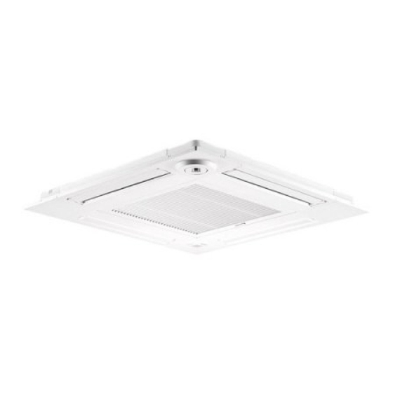
MITSUBISHI ELECTRIC Package Air-Conditioner Grille {Optional Part)
Automatic Filter Elevation Panel Installation Manual
(
PLP-6EAJ
I
PLP-6EAJE (with "i-see Sensor"))
•11,4;,,~)k4!i!iit· 1 it'I
• Before installation, make sure to read all the "Safety precautions that must be followed" and perform
it
accurately.
• The precautions herein provide very important points regarding
safety.
Make sure you follow
them.
• Symbols used in this manual are categorized as follows according to the degree of risk when used improperly:
~
Warning
Describes warnings that must be observed to prevent serious consequences, such as serious injury or death of the user.
Lt,
Caution
Describes precautions that must be observed to prevent damage to the unit.
• After installation, describe the user "Safety Precautions", how to use, and how to care for and clean the unit following the operation
manual,
and test run the unit to check whether there are any problems.
In addition, direct the user to keep this installation manual together with the operation manual, and, should the users change, to give the manuals to the new user.
~Warning
Wiring must be done properly using specific cables and fixed so
Do not mix substances other than the designated refrigerant in
that external pressure from the cable will not transmit to the
the refrigerant cycle when installing and/or moving the unit.
terminal area. Never splice the cables for wiring.
• If air or other substances mix in, abnormal high-pressure will occur in
• If the connection and/or fixation are not done properly, or if the cables
the refrigerant cycle, which may cause explosion.
are spliced, heat or fire may result.
The unit must not be moved or reinstalled by the user.
Never make alterations to the unit.
• If the unit is installed improperly, water leakage, electric shock or fire
• Consult with a dealer for repairs. If alterations are done on the unit or
may result. Ask the dealer or an authorized company to do so.
the unit is repaired improperly, water leakage, electric shock or fire
Use genuine Mitsubishi parts such as humidifier and high
may result.
performance filters (sold separately).
Ask the dealer or an authorized technician to install the unit.
• Ask an authorized company to install. If the unit is installed by the
user improperly, water leakage, electric shock or fire may result.
• If the unit is installed improperly by the user, water leakage, electric
shock or fire may result.
Terminal board cover (panel) of the indoor/outdoor unit must be
Installation must be properly done following this installation manual.
inSialled properly.
• If the unit is installed improperly, water leakage, electric shock or fire
• If the terminal board cover (panel) is installed improperly, fire or
It
electric shock may result due to dust or water.
;:=
m =a
=
y
=
r
=
e
= s=
u
= ·=========================================:
;:=================================================' .
Installation must be done in proper order in case of strong wind
Make sure the refrigerant has not leaked after installation.
such as storms and earthquakes.
• In case the refrigerant leaks into the room and comes in contact with
• If the unit is installed improperly, there is a risk that a fall may result.
a fan
heater,
heater, or stove burner, noxious fumes may be produced.
The unit must be securely installed on a surface that is able to
support the weight of the unit.
• If the surface does not have sufficient strength, accidents may result
due to falling of the unit.
If the unit Is to be Installed In a small room, take measures to
prevent exceeding the concentration limit of refrigerant in the
case of refrigerant leakage.
• Ask a dealer about measures to prevent the exceeding the
concentration limit. If there is any chance of refrigerant leakage and
its concentration exceeds the limit, it may result in lack of oxygen.
Before installation(Environment)
Electrical work must be done by an authorized engineer following
"Technical standards for electrical equipment", "Extension Code"
and this installation manual and using dedicated communication
circuit and rated power voltage/circuit
breakers.
• If the electrical circuit does not have sufficient capacity or if the unit is
installed improperly, electric shock or fire may result.
Turn off the main power before the installation work.
• Otherwise, injury or electric shock may result.
Ventilate the room if refrigerant leaks out during installation.
• When refrigerant comes in contact with fire, noxious fumes may be
produced.
J
~Caution
Do not use the unit in unusual environment.
The unit must not be used for special purposes such as
• If used in an environment with a large amount of volatile oil
(including mechanical oil), steam, or sulfidizing gas or where it is high
in salt content such as a seashore where the outdoor unit may
become blocked by snow, performance may drop significantly or parts
may become
damaged.
the storage of precision apparatuses, food, animals and plants,
and art objects.
• It may cause deterioration in quality of the
objects.
Do not Install the unit above objects that should not get wet.
Do not Install the unit In an area where flammable gas may be
generated, flow in, be retained or leaked.
• In case gas leaks around the unit, fire
or
explosion may result.
• In case humidity exceeds 80% or the drain outlet is blocked, dew may
fall from the indoor unit. When the heating function is on, water leaks
from the outdoor
unit;
intensive drain work may be done to the
outdoor unit as needed.
If the unit Is Installed In a hospital or telecommunlcatlons office, preparation for noise must be adequately completed.
• The effect of inverter equipment, private power
generators,
high-frequency medical devices and radio communication devices may result in
malfunctions and/or damage of the
air-conditioner.
Air-conditioners may affect medical devices or telecommunications devices to interfere with
medical treatment or cause adverse effects such as disturbance of broadcasting and/or noise bursts.
1.
I
Included parts
I
(This manual and following parts are included.)
Standard grille
Part
Number/
0
Grille
Name
Quantity
Shapes/
Sizes
Grille with i-see Sensor
@
Installation gauge
@
Tag
Wireless remote
©
controller for Automatic
@
Battery
Filter Elevation Panel
0
Lithium battery
CR2025
3V
Remote
@
controller
holder
©
screw
2
@
Screw
®
i-see Sensor corner panel
Note: Never force pressure on the vane, it may result in damage.
Parts
G)
to
(J)
above and
...!J
4><16
L!J
jf"
0
:
i
·
~
,.
-
~
"fl
Never force pressure on the lens of !@I-see Sensor corner panel,
it may result in damage.
'
Ceiling surface
Main unit
,,
2,
I
Preparation before installing the grille
I
I
Confirming the location of the main unit
I
•Check whether the opening holes of the ceiling are within the following range:
860 >< 860 to 910 ><910
Measurement
@
Installation gauge
of opening holes
(Insert into the main unit) of the ceiling
•Using included installation
gauge@
,
locate the ceiling surface and
the
main unit.
If location of the ceiling surface and the main unit does not
match,
wind
leakage,
dew fail or damage of the vane may result.
Note: The ga must be in the ran e of 17 to
22.
If it exceeds or fails below the
range,
•Turn off the main power (short circuit
breaker).
~
Turn off the main ower.
~ Warning
•If the main power is not turned
off,
injury or electric shock may result.
[Remarks]
The grille must not be painted by the user.
•It may result extreme malfunction or the damage of parts.
Ask the dealer or an authorized technician to aint.
I
Installing the wired remote controller
I
•The intake grille elevation function can be controll ed with
the
wired remote
controller.
There are 2
methods
for controlling the intake grille elevation fun ction: Use the elevation function for all the main units which are
controlled by the remote controller at once, and use the elevation function for each main unit
individually.
(Please refer to the operation manual for the operation method.)
Install the remote controller in a place where you can observe all the indoor units managed with it.
Otherwise, the lowering
grille
may hit people or objects and
cause
damage to them.
I
Installing the remote controller holder (For
Automatic
Filter Elevation Panel)
I
•The remote controller holder is included. Use the holder to prevent losing the wireless remote
controller.
•Install the wireless remote controller for Automatic Filter Elevation Panel in the following locations.
• Locations that
are
not exposed to direct sunlight
• Locations in which it is easy to
operate the
• Locations that are not near sources of heat
remote
controller and
see
its display
• Locations that are not exposed to cold air (hot air)
• Locations that are out of
the
reach of children
being blown from the indoor unit
• Locations that are not exposed to oily
smoke,
and so on
•To install the wi reless remote
controller for Automatic
Filter Elevation Panel, secure the remote
controller holder
to a w ail using the included screws, and then fit the wireless remote controller for
Automatic
Fille
r
Elevation
Panel
into
the
holder.
I
Removing the intake grille!
•Remove the tape that
sec
ures the intake grille and remove the intake grille from the grille.
Note:
You will find
the
limit switch for storing and detecting intake
grille
shown in the right
figure.
Make sure you do not damage the limit switch when operating.
I
Removing the corner panel
I
~
l
Screw
-r
~~
lose-up
• Loose the 4 screws on the corner,
I..' : &>!
slide
the corner panel in
the
direction
LI
~
crew
of the arrow (1) in the figure and
A:f
¥
~
remove the corner panel.
Corner panel
@
Wireless remote
controller for Automatic
Filter Elevation Panel
!ID
Remote
controller holder
-
-- - -
--
- - - - - - - -
-~
- - - - - - - -
-~
3,
I
Selection of air outlets
I
•You can select 11 different patterns of air outlet
directions
on
this
grille.
•
Select a
pattern of
air
outlet
directions.
More than two directions must be selected.
Notes
1.
When changing the number of
directions,
you need an air
outlet shutter plate, which
is
optional part. An air outlet shutter
plate will be attached to
the
indoor unit; configuration must be
done before
attaching the
grille
on the main unit.
2.
Do not select
2
directions in a hot and humid environment.
(Dew formation or dew drop may result.)
4 directions
3 directions
2
directions
§ (
1
pattern
) ( 4 patterns )
( 6
patterns
)
'fl
Initial setting Block 1 of the air outlets on Block
2
of
the air
outlets on
~
the main unit with shutter
the
main unit with
shutter
'5
❖ ·-o
'¢.oo.
~
V
c>~~
~
0
"'
i
CL
Before installation(Relocation)
~Caution
Do not neglect damaged platforms.
• If left damaged, the unit may fail and result in
injury.
Transport of the product must be done carefully.
• In principle, products over 20 kg must be carried by two or more
people.
Make sure you move the product holding only the designated
handle but not a PP band and such. Use protectors to prevent injury;
do not touch the fins or the edge of part with your bare hands.
Appropriately dispose of packages.
• Packaging may contain metal objects such as "nails" and wood chips.
So injury may result if disposal is neglected.
Make sure that the joints are locked securely and they do not
come off from all of 4 holes.
• Otherwise, the intake grille may drop off and cause an injury or a
failure.
Before electrical work
Do not wash the air-conditioner.
• Doing so may cause electric shock.
J
Drain piping must be done properly according to the installation
manual to drain water and must be heat Insulated to prevent bedewlng.
• If piping is not properly
installed,
water leakage may result, which will
make the
ceilings,
floors or other household Items wet.
Make sure heat insulation for refrigerant piping is properly
installed to prevent bedewing.
• If heat insulation is not done
properly,
bedewing of the surfaces such
as piping may
result,
which will make the
ceilings,
floors,
or other
valuable items wet.
• Insulation for the joint part must be done after an air tightness test.
Make sure to hang the safety strap of the intake grille while
temporarily installing the grille.
• Otherwise, the intake grille may drop off and cause an injury or a
failure.
~Caution
Make sure to install a short circuit breaker to the power.
Unit must be grounded.
• If a short circuit breaker is not
installed,
electric shock may result.
Use proper electrical cables to meet the standard for current
capacity.
• Do not connect the ground wires with ground wires for gas pipes,
water pipes, conductor
rods,
or telephones. If the unit is not properly
grounded, electric shock may result.
• If improper electrical cables are used, short
circuit,
heat, or fire may
result.
Use fuses with appropriate capacity such as short circuit
breaker,
hand switch (switch
+
type B fuse), and circuit breakers for wiring
devices.
Electrical wiring must be done without tension.
• If there is tension on the cables, wire disconnection, electric shock,
or fire may resu It.
• If fuses,
wires,
and copper wires with larger capacities are used
,
damage or fire may result.
Start the electrical work after turning off the main power.
•
Otherwise,
electric shock, damage, or failure may result.
Before test runs
~Caution
Do not operate the unit without the grille or
guard.
Do not touch refrigerant piping when operating with bare hands.
• If you touch rotating, hot or high-voltage parts of the
equipment,
injury may result from being snagged
or
burnt, or from electric shock.
• Refrigerant piping when operating becomes cold and hot, depending
on the condition of the flowing refrigerant. If touched with bare hands,
frostbite or burns may result.
Do not operate the unit with wet hands.
Do not turn the unit off soon after operation stops.
• Electric shock may result.
Turn It on more than 12 hours before operation.
• Make sure you wait for more than 5 minutes. If it is turned off too
soon, water leakage or damage may result.
Do not operate the unit without air filters.
• If operation starts as soon as the unit is turned on, damage may
result. Do not turn it off during the season.
• Dirt may get clogged inside and may
result
in
damage.
3,
I
Selection of air outlets
I
(continued from the previous page)
•Change the settings depending on the number of air outlets and the ceiling height where the main unit is
installed.
If not changed, failure may result or users may feel discomfort.
Note: Do not set up for low ceilings in a hot and humid environment. (Dew drop may result.)
I
When used in combination with PLA-EA
I
Configuration will be done on the remote controller. Refer to the section "Function
Setting"
in the installation manual
of the remote controller or the section "Function Setting on the Remote
Controller"
in the installation manual of the main unit.
I
When used in combination with PLFY-EM
I
Set up the switches on controller board of the main unit as shown in the following table.
<Ceiling height and number of air outlets>
Main unit Type
20 to80 Type
Low ceiling
Standard
High ceiling
Low ceiling
100 to 125 Type
Standard
High ceiling
sw21-1 lsw21-2 sw21-1lsw21-2 sw21-1lsw21-2 sw21-1 lsw21-2 sw21-1
I
sw21-2 sw21-1 lsw21-2
OFF
I
ON
OFF I OFF
ON
I
OFF
OFF
I
ON
OFF
I
OFF
ON
I
OFF
4 directions
SW21 -3 OFF
2.5m
2.7m
3.5m
2.7m
3.2m
4.5m
SW21-4 ON
3 directions SW21 -3 OFF
2.7m
3.0m
3.5m
3.0m
3.6m
4.5m
SW21•4 OFF
2 directions
SW21-3
ON
3.0m
3.3m
3.5m
3.3m
4.0m
4.5m
SW21-4 OFF
Note: Switch setting is necessary except for the column highlighted in gray. (Column highlighted in gray is the initial
setting).
4.1
Installing grille
I
<Hook is in the raised
position>
1)
Preparations
Make sure
to flip 2 hooks on
the
grille
up.
2)
Temporary installation of grille
Join the corner of drain pipe on the main unit with
the
corner with
hole
on the grille and put them
together temporarily by hanging the hook of the
grille to the claw of the main unit.
•Make sure the lead wires of the grille do not get
caught between
the
main unit and the grille.
•Never force pressure on the grille while the
temporary
installation.
It may result in
accident
and damage.
3)
Fixing the grille
•By tightening the pre-installed screws, fix the grille onto the main unit.
Note:
Make sure there is no gap between the main unit and the grille or
between
the
grille
and
the ceiling
surface.
r
!
~
~~·' "
C ·1·
c:::: rf
\
eI Ing su ace
Grille
•If there
is
a gap between the grille and
the
ceiling:
With the grille attached, slightly
adjust the installation height of
the
main unit
and clear
the
gap.
[Remarks]
When tightening the screw, make sure that
the tightening torque is 2.8N • m to 3.6N · m.
Never use an impact screw driver.
• It may result in parts
damage.
Lead wires
of
the grille
4)
Wiring
conne
ctions
r
..l!L~
+---1--ir-
CNV
connector
I
Wiring connections for
vane
motor
I
1.
Loose the 2 screws fixing the electrical box cover on the main unit, and slide the cover to open.
2.
Make sure to connect a connector for vane motor
(white,
20 poles) to CNV connector (white)
on the controller board of the main unit.
3. Lead wires that lead off the grille must be held together without slack using a clamp into the
electrical
box.
/'ii
Note: Lead wires of the grille must
be
held together using a clamp on
the
main unit so
Electrical box
·,
that they
do
not contact
the
strings of elevation
machine
motor box.
!Wiring connections for elevation machine
I
4.
Roule the lead wires
(blue,
4
poles)
of
the
elevation
machine
of
the
grille
from
the side
of the
electrical box on
the
main unit.
5.
Make sure to connect them to CN4G
(blue)
on the controller board of
the
main unit.
6. Earth
wires
of
the grille
must be fixed with
the
included
screws
in the electrical box of
the
main unit.
Indoor unit must be grounded.
~Caution
• Do not connect
the ground wires
with ground wires for
gas pipes,
water
pipes,
conductor
rods,
or
telephones.
If
the
indoor unit is
not
properly grounded,
electric
shock may result.
Ground wire
fixing position
7.
Lead wires for elevation machine of the grille must be fixed with the cable band without slack
inside the electrical box
.
on the
controller
board
Clamp
Continued to
the
next page
Advertisement


