
Related Manuals for McIntosh MC901


Summary of Contents for McIntosh MC901
- Page 1 McIntosh Laboratory, Inc. 2 Chambers Street Binghamton, New York 13903-2699 Phone: 607-723-3512 www.mcintoshlabs.com MC901 Dual Mono Amplifier Owner’s Manual...
-
Page 2: Safety First
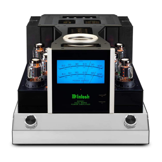
The MC901 Dual Mono Amplifier is the first of its kind Amplifier drawn from McIntosh’s long tradition of uncompromising tube and solid-state Amplifiers. The MC901 combines the finest aspects of tube and solid- state Amplifiers to drive even the most power-hungry Loudspeakers to peak performance. -
Page 3: Table Of Contents
Roll-off for Crossover Points ......16 McIntosh Safety First ............. 2 Roll-off for 1K Crossover Point ......18 Thank you from all of us at McIntosh ....3 Solid State Specifications ........19 Make a Note ............3 You have invested in a precision instrument that will Vacuum Tube Specifications .......19... -
Page 4: One Of A Kind
Output Transformer and Autoformer™. clipping. The 300 Watt Vacuum Tube amplifier section of the MC901 breaks new ground as it’s our first McIntosh’s Unity Coupled Circuit Output Transformer amplifier to feature our new Power Guard Screen Grid... -
Page 5: What Is In The Box
To remove the protective foam, it is necessary to HEAVY. When moving the unit, have enough help to temporarily remove the two Tube Covers. To remove lift the MC901. This will ensure the safety of both you each Tube Cover: and the MC901. -
Page 6: Rear Connections And Switches
When ENABLE is selected, Wire from a Loudspeaker to the from a Loudspeaker to the Vacuum Tube after other connections have the MC901 will power off Solid State Amplifier. Positive (+) Amplifier. Positive (+) and Negative been made after 30 continuous minutes... -
Page 7: Connections On The Back
If you need to switch the INPUT MODE, it is best signals to two separate Loudspeakers from a single to do so when the MC901 is powered off to avoid MC901. Some people have different setups for There are three Input sections: any unpleasant pop caused by switching the cable different genres of music. -
Page 8: Power Control
12AWG, being the larger wire, can be used in all The MC901 is designed for two separate Stereo, a second MC901 is required in all cases. the above cases if desired. The above guidelines are connections to a single Loudspeaker. The Solid for 8 Ohm connections. -
Page 9: Remove Loudspeaker Jumpers
Remove the two Cover Screws from the rear it one quarter of a turn (90°) to secure the Cover Openings of the MC901. These will be used to secure Loudspeaker cable connection (Figure 09). the Terminal Connection Cover (Figure 10 on Do not over tighten page 9). -
Page 10: Sentry Monitor
Module #2, since those MC901. noise waves are going opposite directions. The Output Autoformer doubles the power and cancels noise at the same time. The Vacuum Tube side of the MC901 also takes full advantage of Quad Balanced architecture. With the... -
Page 11: Mc901 Connection Diagram
Audio Preamplifier Balanced cable Preamplifier to Composite Input Balanced cable to 2nd MC901 Power Control from Preamplifier OUT to IN Power Control OUT to 2nd MC901 IN Solid State to Low Speaker Terminals Vacuum Tube to High/Mid Terminals To AC Power... -
Page 12: Setting The Filters
100Hz and 1kHz are available. The HIGH • Eight KT88 Part Number 165073 The SOLID STATE section of the MC901 has a PASS FILTER will not amplify frequencies below LOW PASS FILTER Knob. This knob should be the roll-off point of the HIGH PASS FILTER. -
Page 13: The Front Of The Mc901
Without this feature the pointer might appear like an endlessly moving blur. The MC901 will function optimally with any correct tube type that is functioning within the design specifications of the MC901. Only when a Tube falls KT88 KT88 outside of the acceptable range will any diminishing of performance be heard. -
Page 14: Meter Control Knob
Center connected by a Power Control Cable. See “Power Control” on page 8 • ON- this position will Power the MC901 On Power Guard LED Power Guard continuously monitors input and ® Power Guard output signals and can dynamically adjust input... -
Page 15: Repacking The Mc901
It is very important that the four plastic feet are attached to the bottom of the equipment. The feet come installed on the MC901. The feet ensure the proper FOAM RINGS equipment location on the bottom pad. Failure to do this will result in shipping damage. -
Page 16: Roll-Off For Crossover Points
Roll-off for Crossover Points The following two graphs represent the roll-off characteristics for various filter crossover settings. The output will taper starting with the selected CROSSOVER POINT. The lines from left to right represent the Crossover Points as noted on the SOLID STATE LOW PASS FILTER Knob: •... -
Page 17: Figure 19- Roll-Off For High Pass Filter
The lines from left to right represent the Crossover Points as noted on the VACUUM TUBE HIGH PASS FILTER Knob: • 100 (A) • 130 (B) • 180 (C) • 250 (D) • 300 (E) • 400 (F) • 550 (G) •... -
Page 18: Roll-Off For 1K Crossover Point
Roll-off for 1K Crossover Point This graph uses a 1k CROSSOVER POINT for both Filters. This demonstrates the combined taper for both the HIGH PASS and LOW PASS Filters. Other CROSSOVER POINTS will have a similiar curve. Frequency (Hz) Figure 20– 1K Roll-off Combined Graph... -
Page 19: Solid State Specifications
+0, -0.5dB from 20Hz to 20,000Hz Standby, less than 0.5 watt +0, -3.0dB from 10Hz to 100,000Hz +0, -3.0dB from 10Hz to 70,000Hz Refer to the rear panel of the MC901 for the correct voltage. Total Harmonic Distortion Total Harmonic Distortion Overall Dimensions 0.005% maximum harmonic distortion at any power level... - Page 20 McIntosh Laboratory, Inc. 2 Chambers Street Binghamton, NY 13903 www.mcintoshlabs.com The continuous improvement of its products is the policy of McIntosh Laboratory Incorporated who reserve the right to improve design without notice. Printed in the U.S.A. McIntosh Part No. 24104900 RevB...
Need help?
Do you have a question about the MC901 and is the answer not in the manual?
Questions and answers