
Related Manuals for Clarke STRONG-ARM CML3


Summary of Contents for Clarke STRONG-ARM CML3
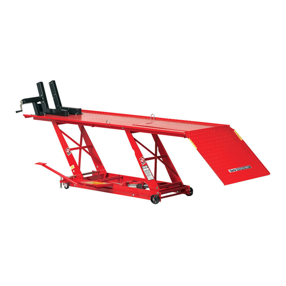
- Page 1 HYDRAULIC MOTORCYCLE LIFT MODEL NO: CML3 PART NO: 7610143 OPERATION & MAINTENANCE INSTRUCTIONS ORIGINAL INSTRUCTIONS GC 0120 rev 5...
-
Page 2: Specifications
GUARANTEE This CLARKE product is guaranteed against faulty manufacture for a period of 12 months from the date of purchase. Please keep your receipt as proof of purchase. -
Page 3: Safety Precautions
8. ALWAYS inspect the lift before use to ensure it is in good condition and replace any damaged or worn parts. 9. ALWAYS use spare parts supplied by Clarke International. Using non- standard parts could be extremely dangerous. 10. ENSURE the operator is trained in both operational and safety aspects of using this product. -
Page 4: Assembly And Preparation
ASSEMBLY & PREPARATION Check to ensure that no damage has occurred during transit. Any damage should be reported to your Clarke dealer immediately. Using a clean, level area, unpack the equipment, laying out the loose items. The motorcycle lift is packed flat in its lowest position. It is fully assembled, except for ancillary items which are fitted as follows. - Page 5 7. When the table is at its full height, it should be possible to insert the locking bar (F), through the hole in the frame, (adjacent to the castor mounting bracket), the corresponding holes in each side of the front lifting arm and out through the opposite side of the frame.
- Page 6 NOTE: A 1HP (MIN) air compressor is recommended for operation, although a 2HP compressor will increase the speed of operation. FURTHER ASSEMBLY When the pedal is assembled you may find that the foot plate is too near the bottom of the safety plate. If so make these adjustments. 1.
- Page 7 If the above procedure does not cure the fault contact you local Clarke dealer. TO LOWER THE LIFT As the weight of the table is taken by the Locking Bar, it is necessary to pump the Foot Lever slightly in order to take the strain and then remove the Locking Bar.
-
Page 8: Operation
OPERATION Always carry out a visual check before use to ensure the lift is serviceable, never take things for granted. For safety purposes, loading the lift is essentially a two man operation. DO NOT exceed the maximum lifting capacity of 450kg (1000lbs) UNDER NO CIRCUMSTANCES should you ride a motorcycle on to the lift, and on no account allow anyone to... -
Page 9: Maintenance
Should any of these be found, do not use the lift. Always have it inspected and repaired by a qualified technician before putting back into use. If necessary, consult your Clarke dealer. 5. If the warning label becomes illegible have it replaced. Contact your Clarke dealer. - Page 10 PARTS LIST CML3 ESCRIPTION ESCRIPTION Hydraulic pump Cotter pin Release valve rod Stop plate R-pin Screw Release valve pin Platform Pump rod Cover Ramp Pump location pin Slave arm Main arm Foot pedal (release) Screw Foot pedal (lifting) Bolt Bolt U-bolt Washer Washer...
-
Page 11: Part Diagram
PART DIAGRAM Parts & Service: 020 8988 7400 / E-mail: Parts@clarkeinternational.com or Service@clarkeinternational.com... - Page 12 PARTS LIST CML3AIR ESCRIPTION ESCRIPTION Hydraulic pump Cotter pin Release valve rod Stop plate R-pin Screw Release valve hinge pin Platform Pump rod Cover panel Ramp Pump location pin Slave arm Bolt Main arm Foot pedal (release) Screw Foot pedal (lifting) Bolt Bolt U-bolt...
- Page 13 ESCRIPTION ESCRIPTION Hinge shaft Control valve Air motor Airline coupling Air hose assembly Cross support Parts & Service: 020 8988 7400 / E-mail: Parts@clarkeinternational.com or Service@clarkeinternational.com...
- Page 14 PART DIAGRAM-CML3AIR Parts & Service: 020 8988 7400 / E-mail: Parts@clarkeinternational.com or Service@clarkeinternational.com...
-
Page 15: Declaration Of Conformity
DECLARATION OF CONFORMITY Parts & Service: 020 8988 7400 / E-mail: Parts@clarkeinternational.com or Service@clarkeinternational.com...
Need help?
Do you have a question about the STRONG-ARM CML3 and is the answer not in the manual?
Questions and answers