Table of Contents
Advertisement
Quick Links
Advertisement
Table of Contents

Related Manuals for Life Fitness Synrgy 180


Summary of Contents for Life Fitness Synrgy 180
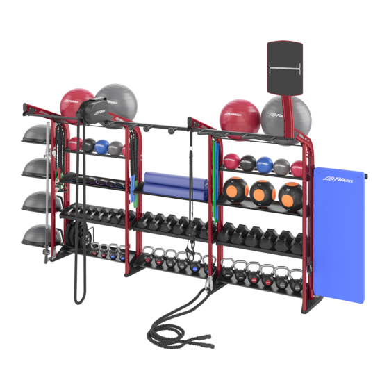
- Page 1 Synrgy 180 S180-CORE, S180-ADD and S180-SIDE Owner’s Manual 1012835-0001 REV AA...
- Page 3 Sales/Marketing Email: vertrieb@lifefitness.com Latin America and Caribbean* Hong Kong Spain Life Fitness, Inc. Life Fitness Asia Pacific LTD Life Fitness IBERIA Columbia Centre III 32/F, Global Trade Square C/Frederic Mompou 5,1º1ª 9525 West Bryn Mawr Avenue 21 Wong Chuk Hang Road 08960 Sant Just Desvern Barcelona Rosemont, IL 60018 U.S.A.
- Page 4 User and Service Documents Link https://www.lftechsupport.com/web/document-library/documents Additional information is available online using the link above. أ علاه إل ر إبط باستخدإم إ لإ ن تر نت على إضافية معلومات تتوفر 点击上面的链接可在线获取更多信息。 Flere oplysninger er tilgængelige online gennem linket ovenfor. Bijkomende informatie is online beschikbaar via bovenstaande link. Vous trouverez plus d'informations en ligne à...
-
Page 5: Table Of Contents
Gym Wipes® is a registered trademark of the 2XL Corporation. PureGreen 24 is a trademark of Pure Green. © Copyright 2019, Life Fitness, LLC. All Rights Reserved. Life Fitness, Hammer Strength, Cybex, ICG and SCIFIT are registered trademarks of Life Fitness, LLC and its affiliated companies and subsidiaries. Brunswick and related trademarks used under license from Brunswick Corporation. -
Page 6: Safety Information
Installation • Life Fitness requires that all equipment be secured to a solid, level surface to stabilize it and eliminate rocking or tipping over. This must be performed by a licensed contractor. See Bolt to Floor Guidelines for installation proce- dure. -
Page 7: Warning And Cautions
• Only add weight plates up to the load limits of the unit. Make sure all weight plates are completely placed on the weight rod. • Never exceed the load rating for any plate loaded station, body weight station, bench or other free weight device; including specific weight rod and band peg limits. -
Page 8: Assembly
2. Assembly Frame Components Item Description Frame Left Body Weight Training Anchor Right Body Weight Training Anchor Left Foot Cover Right Foot Cover End Cap Suspension Anchor Chin Option Cover... - Page 9 Option Categories Item Description Chin Options Stability Ball Storage Frame Top Options Frame Bottom Options Shelf Options Side Storage Option...
- Page 10 Option Types ACTION See page 8 for table...
- Page 11 Option Types Table Item Description 1 Chin Options Suspension Chin Multi Grip Chin Rock Chin 2 Stability Ball Storage Stability Ball Storage 3 Frame Top Options Rope Pull Heavy Bag Anchor Wall Ball Target 4 Frame Bottom Options Power Pivot Battle Rope Anchor 5 Shelf Options Accessory Shelf...
-
Page 12: Hardware List
Hardware Item Description 7/16" Hole Plug 8 x 3/4" Screw Grommet Retainer Socket Nut 1/4" Spacer M10 Nut M10 Washer Concave Washer M10 X 85mm Bolt M10 X 80mm Bolt M10 X 60mm Bolt M10 X 55mm Bolt M10 X 30mm Bolt M10 X 25mm Bolt Snap Link 1/2"... -
Page 13: Tools Required
Tools Required Item Description Qty. 1/2" Wrench 3/4" Wrench 17mm Wrench 3mm Hex Wrench 7mm Hex Wrench #2 Phillips Screwdriver Rubber Mallet See Bolt to Floor Guidelines section for required anchoring tools. -
Page 14: Assembly Guidelines
Assembly Guidelines When installing two options side by side: Do not use 1/4" spacers if options share same mounting holes. When installing Power Block and Dumbbell Storage: Utilize 15 degree tilt feature. When installing the Mat Holder: Utilize 5 degree tilt feature, ensuring the mat peg is angled upward. - Page 15 Shelf and Side Option Clearance Minimum Open Bolt Bottom Shelf Holes Required above Bottom Shelf *Example shown in Accessory Shelf* Image on Right Dumbbell Shelf Power Pivot BOSU Plus Shelf* Side Dual Rail (medicine balls) Side Dual Rail (wall balls) Side BOSU Storage (Left or Right) Side Accessory Storage Side Power Block Pro 50...
- Page 16 Side Storage Compatibility Shaded sections signify the occupied positions of the side option with its accessories. *Optional Workout Board can be fitted into the #3 position.
-
Page 17: Assembly Procedure
Assembly Procedure Install Chin Option (if equipped) 1. Loosely install Chin Option and hardware Item Description Qty. M10 X 80mm Bolt Retainer Left Body Weight Training Anchor Socket Nut Chin Option Right Body Weight Training Anchor NOTE: Body Weight Training Anchors used only when ter- minating Left and Right ends of unit. - Page 18 Assembly Procedure Install Stability Ball Storage (if equipped) 1. Loosely install Stability Ball Storage and hard- ware. Item Description Qty. M10 X 80mm Bolt Retainer 1/4" Spacer Socket Nut Stability Ball Storage...
- Page 19 Assembly Procedure Install Shelf Option (if equipped) 1. Loosely install Shelf Option and hardware. Item Description Qty. M10 X 80mm Bolt Retainer 1/4" Spacer Socket Nut Shelf Option For Stall Bar Option 1. Loosely install Stall Bar Weldments and hard- ware.
- Page 20 Assembly Procedure Install Frame Top Option (if equipped) 1. Loosely Install Frame Top Option and hard- ware. Item Description Qty. Frame Top Option M10 X 80mm Bolt Retainer 1/4" Spacer Socket Nut For Rope Pull Option 1. Loosely attach Rope Pull Option and hardware. Item Description Qty.
- Page 21 Assembly Procedure Install Frame Bottom Option (if equipped) 1. Loosely install Frame Bottom Option compo- nents and hardware. Item Description Qty. Socket Nut 1/4" Spacer Retainer M10 X 80mm Bolt Weight Plate Storage M10 X 60mm Bolt Power Pivot Elbow NOTE: Weight Plate Storage can be orientated on Left or Right side of frame (Right shown).
- Page 22 Assembly Procedure Install Frame Bottom Option (if equipped) 3. Assemble Weight Bar. Item Description Qty. Weight Bar Assembly M10 X 60mm Bolt Retainer Concave Washer Socket Nut Power Pivot Elbow 4. Store Power Pivot Bar Raise bar and place into stored position.
- Page 23 Assembly Procedure Install Side Storage Option 1. Loosely install Side Option and hardware. Item Description Qty. M10 X 80mm Bolt Retainer 1/4" Spacer Socket Nut Side Dual Rail Option For Foam Roller Option 1. Orientate bracket for Left or Right placement. For Stability Ball 1.
- Page 24 Assembly Procedure Install Side Storage Option For Workout Board Option 1. Install Workout Board frame. Item Description Qty. M10 X 80mm Bolt Retainer 1/4" Spacer Socket Nut Workout Board Frame End Cap 2. Install Workout Board to frame. Item Description Qty.
- Page 25 Assembly Procedure Final Assembly Follow these steps to complete assembly. 1. Tighten all hardware Torque hardware to 18-20 ft-lbs (24.4-27.1 Nm). 2. Anchor Unit to Floor Refer to Bolt to Floor Guidelines in this manual for further details. Item Description Qty.
- Page 26 Assembly Procedure Final Assembly 4. Attach End Caps and Hole Plugs Fill holes with End Caps and Hole Plugs; tap flush into frame. Item Description Qty. End Cap 7/16" Hole Plug 5. Apply Accessory Labels (if applicable): Item Description Qty. Accessory Label Sheet * Label can be added to front and/or top of Dumbbell shelf (both options shown).
-
Page 27: Product Information Specifications
3. Product Information Specifications Weights and Dimensions Weight Dimensions D x W x H Model Pounds Kilograms Inches Centimeters 47 x 59 x 95 119.4 x 150 x 241.3 S180-CORE 79.8 47 x 10 x 95 119.4 x 25.4 x 241.3 S180-ADD 39.5 7 x 49 x 5... -
Page 28: Footprint And Live Area
3. Product Information Footprint and Live Area LIVE AREA FOOTPRINT Note: Some options increase Footprint and Live Area + 6” (15 cm) Rope Pull + 21” (53 cm) + 3” (7.5 cm) + 38” (97 cm) + 38” (97 cm) Wall Ball Target + 2.75”... -
Page 29: Maintenance Procedures
4. Maintenance Procedures Maintenance Schedule Action Weekly Monthly As Needed Frames Inspect Paint Hardware Frame • Frames with a standard, non-abrasive, wax finish. Inspect • Hardware. Check for loosening. Tighten as required. • Frames. Inspect for wear and damage. • For paint chips. -
Page 30: Warranty
Who Pays Transportation and Insurance For Service If the Product or any covered part must be returned to a service facility for repairs, We, LIFE FITNESS, will pay all trans- portation and insurance charges for the first year. You are responsible for transportation and insurance charge after the first year. -
Page 31: Warranty Coverage
Warranty Coverage NOTE: There is no warranty coverage for labor on Strength Products. Item 90 Days 10 Years Frame Hardware / Mechanical Items Not Specified 6. Exercise General Exercise Information Intended Use The intended commercial use of this machine is to aid exercise and improve general physical fitness. Prior to Exercise Prior to starting a training program, get a complete physical exam to make sure your physician agrees that you are ready. -
Page 32: Bolt To Floor Guidelines
6. Bolt to Floor Guidelines Introduction LIFE FITNESS designs its products to be stable when used as designed. Because strength training is dynamic, we cannot predict how users will ultimately use the products in all circumstances. Therefore, LIFE FITNESS recommends that strength training equipment be secured to a solid, level surface to stabilize and eliminate rocking or tipping over. -
Page 33: Anchor Types
Pullout Force LIFE FITNESS specifies Hilti™ static and dynamic anchors. According to the anchor manufacturer, the recommended design pullout force (in tension) for the specified anchors, when properly installed in cracked concrete, is provided in the side table. This table should be used for reference only; for additional and up-to-date information on the anchor... -
Page 34: Tools Required
Selected Anchor Design Resistance in Tension * 830 lb KH-EZ 1/4” x 4” 3.3 kN HUS-H 6MM x 120MM 1535 lb KH-EZ 3/8” x 4” 1535 lb KH-EZ 3/8” x 5” 3.3 kN HUS-H 8MM x 120MM 3.3 kN HUS-H 8MM x 150MM 2000 lb HSL-3/8 4”... -
Page 35: Dynamic Hsl-3 8/40 Anchor Procedure
Dynamic HSL-3 8/40 Anchor Procedure 1. Place unit into position to be mounted. 2. Wearing protective glasses, drill down into flooring perpendicularly to the required depth, ensuring that the foot thickness is being ac- counted for; refer to Anchor Selection and Foot Dimensions Section. -
Page 36: Dynamic Hst Safety Stud Anchor Procedure
Dynamic HST Safety Stud Anchor Procedure 1. Place unit into position to be mounted. 2. If necessary, cut HST Safety Stud Anchor to length before installation, leaving enough length to ensure proper concrete embedment (see Anchor Section for embedment depth required) and proper tightening torque (44 Foot- Pounds/60Nm). -
Page 37: Foot Dimensions
Foot Dimensions Use below image to determine foot specifications.
Need help?
Do you have a question about the Synrgy 180 and is the answer not in the manual?
Questions and answers