
Related Manuals for Honeywell HON R100NG Series


Summary of Contents for Honeywell HON R100NG Series
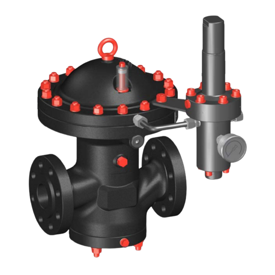
- Page 1 HON R100NG Gas pressure regulator with HON P095NG pilot User and maintenance manual Maintenance parts ...
-
Page 2: Table Of Contents
Contents Contents General considerations About this user manual About the safety notices Description Intended use Device models Labels/Markings Identifying the device Layout and operation Technical specifications Safety Basic safety rules Requirements concerning the workforce, personal protective gear, workplaces ... - Page 3 Contents Decommissioning, storage, renewed start‐up, disposal Disassembling the device Storing the device Putting the gas pressure regulator back into operation Disposing of the device Appendix 10.1 Additional information regarding spare parts 10.2 Spare parts for HON R100NG 10.3 Spare parts for HON P095NG pilot 10.4 Lubricants and threadlockers User manual for HON R100 gas pressure regulator with HON P095NG pilot 3 ...
-
Page 4: General Considerations
Transport Installation Start‐up Set‐up Maintenance Decommissioning, disassembly, renewed start‐up, storage and disposal Target group This user manual is intended for anyone working with the product: Transportation personnel Installation personnel Set‐up and operating personnel Maintenance and service personnel Honeywell offers products with identical functions in a number of different sizes. For this Illustration reason, we are unable to guarantee that illustrations in this user manual coincide with the dimensions of your product. In these cases, the illustrations should be viewed as a concept sketch. Failing to observe the information provided in this document may lead to injuries, including Safety death and material damages. To ensure the safety, any persons handling the product must have read and understood the following parts of this document before they start with any work involving it: the chapter entitled Safety the chapters that describe the work to be done ... -
Page 5: About The Safety Notices
General considerations Copyright © Copyright 2018 by Honeywell Process Solutions Honeywell Gas Technologies GmbH Osterholzstraße 45 34123 Kassel GERMANY Tel: +49 561 5007‐0 Phone number for service: +49 561 5007‐180 Fax: +49 561 5007‐107 Fax number for service: +49 561 5007‐108 E‐mail: gas‐ks@honeywell.com Website: www.honeywellprocess.com www.hongastec.de Printed in Germany Details about the manu‐ The manufacturer is not liable for damages and malfunctions arising from non‐observance of facturer’s liability this user manual and the other applicable documents. Constructive changes The written approval from Honeywell Gas Technologies GmbH, Kassel, is required for any modifications and additions to the product. Any violation will void the legal liability for con‐ sequences arising thereof. About the safety notices Meaning The information contained in the safety notices is intended to prevent personal injury. Safety notices contain the following information: Nature and source of the danger Possible consequences associated with the non‐observance of the notice Procedures for the prevention of personal injury ... - Page 6 General considerations Type of safety notice Description Sign Step‐related safety Safety notices containing specific instructions DANGER notices relating only to the step WARNING CAUTION Additional safety Instruction to observe certain safety notices notice with reference to a location in the document where safety notices containing specific information about dangers, risks and specific instructions for safety procedures can be found Danger levels The safety notices containing specific instructions are identified with a signal word. The signal word represents a certain danger level: Danger level If you fail to follow the instruction, then … And the consequence is … DANGER an accident will happen serious bodily injury or death. WARNING an accident may happen possible serious bodily injury or death. CAUTION an accident may or will happen. minor or moderate bodily injury. Warnings about possible material damages are identified with the word Attention in this Warnings about material ...
-
Page 7: Description
Description Description Contents Topic Page Intended use Device models Labels/Markings Identifying the device Layout and operation Technical specifications Intended use Intended use HON R100NG gas pressure regulators featuring an HON P095NG pilot can be used to main‐ tain the outlet pressure of a gas constant within a regulating line regardless of the influence of disturbance variables such as inlet pressure changes and/or discharge changes. In addition, these gas pressure regulators can be used to implement an active‐monitor regulator configu‐ ration. It can be used in transfer stations of gas transportation networks, in power plants and industrial plants. HON R100NG gas pressure regulators featuring an HON P095NG pilot are suitable for use with natural gas or dry, non‐aggressive industrial gases. Note: The utilization limits of the device with regard to the medium, operating pressure and operating temperature can be gathered from the type plate attached on the device or the technical specifications. The use under different operating conditions must be coordinated in consultation with the manufacturer. Limitations of use Please observe the following limitations of use: Do not use the device for any media other than those mentioned in the intended use or those discussed with and approved by the manufacturer. Do not use the device in any installation position other than the one documented in this user manual. ... -
Page 8: Device Models
Description Device models Gas pressure regulator Gas pressure regulators consisting of an HON R100NG regulator unit combined with an versions HON P095NG pilot are available in a number of versions. These versions are derived from the various possible combinations between the various pilot and actuator assembly versions. HON R100NG actuator The HON R100NG actuator assembly is available in two designs. In addition to the two basic assembly models configurations – the standard version and the fail‐open version – an active monitor regulator circuit can be set up as well. The table below shows the different characteristics of these designs: HON R100NG HON R100NG‐FO Standard version fail‐closed fail‐open 1", 2", 3", 4", 6", 8" 1", 2", 3", 4", 6", 8" nominal inlet sizes nominal inlet sizes ANSI class 150 to class 600 pressure ratings ANSI class 150 to class 600 pressure ratings HON P095NG pilot mod‐ The following table shows which models are available: els Description Design Setpoint range Medium‐pressure model ... -
Page 9: Labels/Markings
Description Labels/Markings Illegible labels Illegible information on the device poses a risk of injury due to resulting erroneous opera‐ tion, use, or installation. Labels, as well as inscriptions and stamping on the device, can eventually become soiled or otherwise unrecognizable to such an extent that users will not be warned effectively of hazards and may be unable to follow required operating instructions. This will pose a risk of injury. Make sure to always keep all relevant labels in good condition so that they will be easily legible. Immediately replace damaged and missing labels. Labels on the The following labels/markings can be found on the front of the actuator assembly: HON R100NG actuator Figure No. Meaning assembly 1 Name of the device 2 Nominal size and pressure rating 3 Body section materials 4 Arrow indicating the direction of flow The following labels/markings can be found at the top of the actuator assembly: Figure No. Meaning 1 ANSI pressure rating 2 Material ... -
Page 10: Identifying The Device
Description Nameplate For a detailed list of the information on the nameplate and what it means: Identifying the device (see page 10) Labels on connection Small labels must be used to color‐code and explicitly name the actuator assembly’s connec‐ lines tion lines based on what the lines are intended for and their minimum nominal size. Identifying the device Identifying the gas pres‐ Make sure you have the right manual for your gas pressure regulator. sure regulator Use the nameplates to identify the actuator assembly and the pilot. Verifying the technical Make sure that the on‐site conditions match the information on the nameplates and the specifications technical specifications. Technical specifications (see page 17) Locating the type plate of The type plate of the actuator assembly can be found here: the actuator assembly Figure No. Description 1 Actuator assembly side User manual for HON R100 gas pressure regulator with HON P095NG pilot 10 ... - Page 11 Description Interpreting the type The details on the type plate have the following meaning: plate of the actuator Figure No. Meaning assembly 1 Model name 2 Manufacturer 3 Nominal size 4 ANSI class 5 Temperature range 6 Maximum allowable pressure 7 Manufacturing date 8 Directive 9 Fluid group 10 CE marking In conformity with standard, e.g., DIN EN 11 334 12 Customer revision No. 13 Manufacturing date (year) 14 Pressure rating 15 Installation length 16 ...
-
Page 12: Layout And Operation
Description Interpreting the type The details on the type plate have the following meaning: plate of the pilot Figure No. Meaning 1 Manufacturer 2 Name of the device 3 Manufacturing date 4 Setpoint range 5 Specific set range 6 Response pressure setpoint 7 In conformity with standard, e. g., DIN EN 334 8 CE marking 9 Serial number 10 Customer revision No. 11 Maximum inlet pressure 12 Temperature range Layout and operation Assemblies The gas pressure regulator is made up of the following assemblies: Figure ... - Page 13 Description Actuator assembly con‐ Actuator assembly configuration: figuration Figure No. Description 1 Dome 2 Diaphragm unit 3 Moving parts 4 Valve housing 5 Bottom cover The parts (3) that move with the diaphragm unit (2) are shown in dark gray. Actuator assembly pres‐ Figure Color Meaning sure sections Inlet pressure Outlet pressure Motorization pressure User manual for HON R100 gas pressure regulator with HON P095NG pilot 13 ...
- Page 14 Description Actuator assembly con‐ The HON R100NG and HON R100NG‐FO actuator assembly versions feature the following nection lines ports: Figure No. Connection Front: 1 Motorization pressure 2 Outlet pressure 3 Inlet pressure Back: 1 Outlet pressure feedback How the actuator as‐ HON R100NG HON R100NG‐FO sembly works In a depressurized state, the compression In a depressurized state, the compression spring will push the diaphragm upward so that spring will push the diaphragm downward, the valve plate will close, creating a seal at the causing the valve plate to be pushed downward edge leading to the support cage (fail‐close). and opening a gap between the inlet pressure The motorization pressure will produce a force and outlet pressure areas (fail‐open). ...
- Page 15 Description Pilot components The HON P095NG pilot is made up of the following components and housing parts: Figure No. Description 1 Spring dome housing 2 Upper diaphragm unit 3 Control stage housing 4 Lower diaphragm unit 5 Upstream pressure stage housing Pilot fittings The HON P095NG pilot features the following fittings: Figure No. Connection 1 Outlet pressure (measuring line) 2 Outlet pressure (discharging) 3 Pressure gauge (loading pressure) 4 Inlet pressure 5 Motorization pressure (actuator assembly) 6 Vent line (ambient pressure compensation) User manual for HON R100 gas pressure regulator with HON P095NG pilot 15 ...
- Page 16 Description Pilot pressure sections Figure Color Meaning Inlet pressure Loading pressure Motorization pressure Outlet pressure Atmospheric pressure The pilot’s set screw is used to tighten the pilot spring. The spring, in turn, produces a How the pilot works force component that acts on the upper diaphragm from above. The outlet pressure produces a force component that acts on the upper diaphragm from below. The force components acting on the upper diaphragm are used by the diaphragm in order to compare the setpoint and the process value. Depending on how the dia‐ phragm moves, a larger or smaller gap between the valve and the motorization pres‐ sure stage will be opened. The motorization pressure is regulated with this gap. The inlet pressure is conveyed into the lower chamber of the upstream pressure stage. This pressure is conveyed into the chamber above the lower diaphragm through the valve. The pressure reduced by the valve is the loading pressure, which produces a force component that acts on the lower diaphragm from above. The outlet pressure is conveyed into the pilot from the other side. This pressure is con‐ veyed into the chamber below the lower diaphragm unit through a hole in the housing. There, the outlet pressure produces a force component that acts on the diaphragm from below. The force components acting on the lower diaphragm are used by the diaphragm in order to compare the setpoint and the process value. Depending on how the dia‐ phragm moves, a larger or smaller gap between the upper valve and the motorization pressure stage will be opened. The motorization pressure is regulated with this gap. Depending on the gas pressure and on the set setpoint, the resulting motorization pressure will vary. ...
-
Page 17: Technical Specifications
Description The motorization pressure causes the gas pressure regulator being operated to open and close as appropriate. Technical specifications Characteristic device Criterion Value values and materials Up to 100 bar Connection pressure Between 0.5 and 60 bar Outlet pressure range (Wh) ‐4 °F to +140 °F Operating temperature (‐20 °C to +60 °C) Cast steel, steel, NBR, PTFE Actuator assembly materials Steel, brass, NBR, FKM Pilot materials Pressure rating and There are various flange facings for the nominal diameters of 1" (DN 25); 2" (DN 50); flange facing standards 3" (DN 80); 4" (DN 100); 6" (DN 150) and 8" (DN 200), as specified in the following stand‐ ards: ... - Page 18 Description HON R100NG dimensions and weights when using HON P095NG pilot as an example Size Class A B C L Weight* inch inch inch inch lbs (kg) (mm) (mm) (mm) (mm) 1" 60 300 (DN 25) (27) 12.21 9.57 3.19 8.50 (310) (243) (81) (216) 1" 60 ...
- Page 19 Description Pilot dimensions and All specifications apply to both the MP and HP versions. weights Imperial system: Weight A B C D lbs (kg) in (mm) in (mm) in (mm) in (mm) 17.6 4.44 12.99 4.92 2.75 (8.0) (113) (330) (125) (70) Accuracy class AC and The following classifications apply as defined in EN334: look‐up pressure class SG Outlet pressure area pd Accuracy class AC Lock‐up pressure class Lock‐up pressure range [bar] SG zone SZ <14.5 <14.5 psi (1 bar to 10 ...
- Page 20 Description Connection lines An overview of the connection lines for the HON R100NG actuator assembly and the HON P095NG pilot can be found in Layout and operation (see page 12). The actuator assembly’s ports have the following sizes: Device model Connection Size Pipe diameter HON R100NG 10 mm, 12 mm, Motorization pressure G1/4" HON R100NG‐FO 1/2" HON R100NG 10 mm, 12 mm, Outlet pressure feedback G1/2" HON R100NG‐FO 16 mm, 1/2" HON R100NG 10 mm, 12 mm, Outlet pressure G1/4" HON R100NG‐FO 1/2" ...
-
Page 21: Safety
Safety Safety Contents Topic Page Basic safety rules Requirements concerning the workforce, personal protective gear, workplaces Basic safety rules Target group of these These rules are intended for any individuals handling the device. rules Purpose of these rules These rules are designed to make sure that any individuals handling the device obtain de‐ tailed information about the dangers and safety procedures and observe the safety notices contained in the user manual and on the device. If you do not follow these rules, there is a risk of injury including death and material damages. Handling the user manual Observe the following rules: Read the chapter entitled Safety and the chapters relating to your responsibilities in their entirety. It is vital that you have understood these contents. Always keep the user manual close by the device so that you can refer to it again. Include the user manual if you are giving the device away. Handling the device Observe the following rules: Only individuals who meet the requirements set forth in this user manual have permis‐ sion to handle the device. The device’s intended use includes its use in hazardous locations. All work with and on the device must be carried out only after the presence of an explosive atmosphere has been fully ruled out. ... -
Page 22: Requirements Concerning The Workforce, Personal Protective Gear, Workplaces
Safety Operator’s duties oppo‐ In your capacity as the company operating the device, you must ensure the following: site the employees All personnel must meet the requirements corresponding to their duties. All personnel must read and understand this user manual before working with/on the device. All occupational health and safety regulations that apply in your country must be com‐ plied with. Hazards resulting from specific working conditions at the location where the device is being used must be determined by means of a risk assessment and rendered avoidable by means of appropriate operating instructions. All personnel must be provided with the personal protective equipment required for their work. This personal protective equipment must be in good condition at all times. All personnel must wear the personal protective equipment required for their work. Conduct in the event of The device is designed and built such that the employees can work with it without being at risk. In spite of all the precautions, accidents can happen under unfavorable circumstances. accidents Always consult the directives of your company concerning the protection of the workforce. Requirements concerning the workforce, personal protective gear, workplaces Requirements concerning Individuals tasked with handling the device must meet the following requirements: the workforce Personnel Responsibilities Required qualification Any work on and with the device Professional training and experience Skilled person or expert ... - Page 23 Safety Personnel Responsibilities Required qualification Professional training and experience Mechanical Mechanical installation operating pressure equipment and fitter systems Knowledge of the relevant standards and regulations Ability to identify and avoid dangers autonomously Initial start‐up Professional training and experience Tasked with the commis‐ Renewed start‐up operating pressure equipment and sioning systems Knowledge of the relevant standards and regulations Ability to identify and avoid dangers autonomously Professional training and experience Tasked with the installa‐ Set‐up operating pressure equipment and tion systems ...
- Page 24 Safety Requirements for the Any persons handling the device must be equipped with the following personal protective personal protective gear gear: Task Required personal protective gear Industrial protective helmet Start‐up, operation (including partial), Protective clothing cleaning, maintenance, search and remedy Safety harness of errors Ear protection Safety boots with protection for electrostatic dis‐ charge (ESD) Safety goggles Safety gloves Workplace requirements To ensure the safe handling of the device, the personnel must remain at the workplaces intended for performing their tasks. The workplaces for performing the various tasks are at the following locations: Task Workplaces Installation All around the device, depending on the task Start‐up Set‐up Maintenance, repairs ...
-
Page 25: Basics For Installing The Device In A Pipe
Basics for installing the device in a pipe Basics for installing the device in a pipe Contents Topic Page Installation examples Meter run characteristics Operating and measuring lines Alternative application example: Active monitor regulator Installation examples Gas pressure regulating Configuration: line ‐ example 1 Direct acting gas pressure regulator (non‐piloted) With expander without noise reduction element downstream of the gas pressure regu‐ lator Gas pressure regulating Configuration: line ‐ example 2 Indirect acting gas pressure regulator (pilot‐operated) With expander without noise reduction element downstream of the gas pressure regu‐ lator Outlet pressure gauge with protection against overpressure User manual for HON R100 gas pressure regulator with HON P095NG pilot 25 ... - Page 26 Basics for installing the device in a pipe Gas pressure regulating Configuration: line ‐ example 3 Indirect acting gas pressure regulator (pilot‐operated) With expander and integrated noise reduction element Outlet pressure gauge with protection against overpressure Gas pressure regulating Configuration: line ‐ example 4 Indirect acting gas pressure regulator (pilot‐operated) Indirect acting slam‐shut device (pilot‐operated) (two) With expander without noise reduction element downstream of the gas pressure regu‐ lator Legend The numbers have the following meaning: No. Meaning 1 Safety Shut‐Off Valve 2 Gas pressure regulator 3 Pilot 4 Safety relief valve 5 Outlet stop valve armature 6 Sensing point for connection lines (gray area) 7 ...
-
Page 27: Meter Run Characteristics
Basics for installing the device in a pipe No. Meaning 11 Vent line 12 Relief line 13 Blowdown line Following is the meaning of the acronyms: Acr. Meaning DN Nominal size of pipe Undisturbed length of pipe * Shut‐off device with undisturbed flow pattern (ball valve) can be incorporated Meter run characteristics The following recommendations are based on the measuring line connection conditions set Standards used as a basis forth in standards (DIN) EN 334 and (DIN) EN 14382. The company operating the system is the sole party responsible for the meter run working properly. A pipe area with a steady flow pattern must be selected for the sensing point. There Conditions for the meter run must not be any components that disturb the flow directly upstream and downstream of the sensing point, e.g., orifice plates, expanders, bends, junctions, shut‐off devices, etc. The flow rate at the sensing point should not exceed approx. 25 m/s, depending on the system conditions. ... - Page 28 Basics for installing the device in a pipe Upstream of the sensing Depending on the specific system design, the L lengths of the undisturbed pipes upstream point of the sensing point must be (2.5 to 5) x DN of the pipe, with the specifics depending on the gas pressure regulator model and whether or not there is a pipe expander downstream: If … and... then... The nominal size of the pipe is equal to the outlet‐side nominal min. 2.5 x DN size of the gas pressure regulator The nominal size of the pipe is the next larger standard nominal min. 3 x DN A gas pressure regulator with an size expander that is part of the The nominal size of the pipe is device is used two standard nominal size min. 4 x DN increments larger The nominal size of the pipe is more than two standard nomi‐ min.
-
Page 29: Operating And Measuring Lines
Basics for installing the device in a pipe Operating and measuring lines Connection lines between The lines must be arranged and sized in such a way that the devices’ intended function will be device and gas regulating ensured. line Measuring line The measuring line transmits the pressure process value from the sensing point to the measuring diaphragm of a controller or the pilot of a gas pressure regulator or safety relief valve or to the measuring diaphragm of the moni‐ toring device of a slam‐shut device. It needs to be connected to the pipe sideways or upwards separately for each device. In the case of safety equip‐ ment, the measuring line must be connected upstream of the first outlet‐side shut‐off device in such a way that it cannot be shut off. If the measuring line is additionally connected downstream of the first outlet‐side shut‐off device, 3‐way ball valves with negative overlap must be used for switching. These ball valves do not have a valve position in which both measuring lines can be fully closed at the same time. Vent line The vent line is used to connect a measuring diaphragm to the atmosphere. If the measuring unit becomes damaged (e.g., diaphragm rupture), it can start conveying gas. Under certain operating conditions, and following consultation with the manufacturer, vent lines can be omitted if vent valves (HON 915) or safety diaphragm configurations can be used instead. Blowdown line The blowdown line in a safety relief valve is used to divert gas (leaking gas, for example) into the atmosphere. Grouping vent lines or blowdown lines (into a header) is permissible if it does not have a negative impact on the individual devices’ operation. Within this context, it is recommended to have the cross‐sectional area of the header be at least five times as large as the total of the ... -
Page 30: Alternative Application Example: Active Monitor Regulator
Basics for installing the device in a pipe Alternative application example: Active monitor regulator Overview The arrows on the pipes show the direction of flow. Front: Back: Sectional view The numbers have the following meaning: No. Meaning 1 HON R100NG actuator assembly with HON P095NG pilot (monitor regulator unit) 2 HON R100NG‐FO actuator assembly with HON P095NG pilot (active regulator unit) 3 Outlet pressure measuring line User manual for HON R100 gas pressure regulator with HON P095NG pilot 30 ... - Page 31 Basics for installing the device in a pipe No. Meaning 4 Outlet pressure measuring line 5 Outlet pressure feedback 6 Pilot inlet pressure (active regulator unit) 7 Pilot inlet pressure (monitor regulator unit) 8 Gas pressure regulator (1) motorization pressure 9 Outlet pressure 10 Outlet pressure discharging 11 3‐way ball valve 12 Gas pressure regulator (2) motorization pressure 13 Loading pressure 14 Outlet pressure discharging 15 Loading pressure How it works A standard fail‐close actuator assembly is first installed in the pipe run in the direction of flow. The device is then connected to the HON P095NG pilot, which in turn is also connected to the regulating line’s inlet and outlet pressures. Together, the actuator assembly and the pilot make up the monitor regulator unit. Downstream of this setup, a fail‐open actuator assembly is installed with a HON P095NG pilot as well. Together with the HON P095NG pilot, this second actuator assembly makes up the active regulator unit. The outlet pressure is monitored by the upstream monitor regulator unit in addition to the ...
-
Page 32: Transport, Installation And Start-Up
Transport, installation and start‐up Transport, installation and start‐up Contents Topic Page Transporting the gas pressure regulator Installing the gas pressure regulator Installing the device connections Checking the system for leaks Starting up the gas pressure regulator Transporting the gas pressure regulator Heavy transport units Risk of serious injury posed by heavy loads when using cranes for transportation Transporting heavy devices or components with a crane may result in serious impact and crush injuries if the loads start moving in an uncontrolled manner. Loads may only be transported with a crane by a duly qualified person. Markings and information about the center of gravity of the load (if applicable) must be observed. Loads may only be moved under supervision. Suspended loads Risk of serious injury in the event that load handling attachments break while holding a suspended load Heavy loads picked up or transported with hoisting and slinging gear may result in serious impact and crush injuries if the load handling attachments fail. Only fasten the device at the positions intended for the transport. The load‐bearing capacity of the appropriate hoisting equipment must correspond at least to the weight of the load to be transported. Always stand clear of suspended loads. Ensure that no person is within the danger zone. ... - Page 33 Transport, installation and start‐up Preparing for transporta‐ Make sure that the following requirements are met before transportation: tion You have seen and taken into account all instructions on the packaging regarding the orientation of the packed device, the center of gravity, and attachment points. The transport route is clear of obstacles and other barriers, and there is enough space available for the dimensions of the packed device and the handling equipment. Make sure to measure all of the package’s dimensions! The transport route will be able to handle the load exerted by the total weight of the handling equipment and the load being transported. There is enough space for unpacking and installing the device at the installation loca‐ tion. Transporting the device Proceed as follows: Figure Step Description 1 Leave the transport panels (1) on the gas pressure regulator during transport. 2 Rig the sling to the eye bolt (1). 3 Lift the gas pressure regulator. Slowly and carefully transport the gas pressure regulator to the location where it will be installed. User manual for HON R100 gas pressure regulator with HON P095NG pilot 33 ...
-
Page 34: Installing The Gas Pressure Regulator
Transport, installation and start‐up Installing the gas pressure regulator Preparing the materials Prepare the following materials: Flange gaskets Threaded bolts Washers Nuts The quantity and size are dependent on the following criteria: Design and size of the flange Assessing the situation Assess the installation situation. The numbers have the following meaning: Figure No. Meaning 1 Gas regulating line inlet 2 Studs and washers 3 Flange gasket 4 Nuts and washers 5 Gas regulating line outlet Mounting the actuator Proceed as follows: assembly Figure Step Description 1 Remove the protective plates from the ... -
Page 35: Installing The Device Connections
Transport, installation and start‐up Final inspection Conduct a final inspection to check whether the following criteria are met: All screwed connections on the device and supply lines are securely fastened. If … then … at least one criterion is not met, you should correct the error before proceeding with the next task. all criteria are met, you may proceed with the next task. Next task Proceed as follows: Installing the device connections (see page 35) Installing the device connections Operating and measuring Some of the measuring impulse lines will come pre‐installed: lines that are Figure No. Designation, pre‐installed and that category, need to be installed installation condition Front: 1 Motorization line Operating line pre‐installed 2 Outlet pressure measuring line Operating line needs to be installed ... -
Page 36: Checking The System For Leaks
Transport, installation and start‐up Final inspection Conduct a final inspection to check whether the following criteria are met: All screwed connections on the device and supply lines are securely fastened. If … then … at least one criterion is not met you should correct the error before proceeding with the next task. all criteria are met you may proceed with the next task. Next task Proceed as follows: Checking the system for leaks (see page 36) Checking the system for leaks Leak test conducted by Prior to delivery, the manufacturer conducted a pressure and leak test on the gas pressure the manufacturer regulator as specified in DIN EN 334. Leak test at the set‐up The gas pressure regulator installed in the system must be subjected to a leak test at the location (in Germany) setup location as follows: Normative basis DVGW Code of Practice G 491 Test method Bubble test method Test medium Air or inert gas Scope of the test All detachable pipe joints Test equipment Foam‐generating leakage medium ... - Page 37 Transport, installation and start‐up Test configuration The test configuration is as follows (concept sketch): The numbers have the following meaning: No. Meaning 1 Inlet chamber 2 Outlet chamber Inlet stop valve armature 3 Gas pressure regulator 4 5 Blowdown line shut‐off device 6 Outlet stop valve armature Checking the system for Proceed as follows: leaks Step Description 1 Slowly close the outlet stop valve armature. 2 Apply the test medium to all detachable pipe joints. 3 Observe the test medium on all detachable pipe joints for several minutes. If … then … the system is leak‐proof. no foam or bubbles are formed, the system may be put into operation. the affected pipe joint is leaking. Foam or bubbles are formed, ...
-
Page 38: Starting Up The Gas Pressure Regulator
Transport, installation and start‐up Starting up the gas pressure regulator Pressurized parts Risk of injury posed by bursting parts in the event that they are subjected to pressure in the wrong direction The device has been designed for a specific direction of flow, which is labeled on the device. Subjecting the device to pressure in the wrong direction may result in serious injury caused by bursting parts. Pressurize the system only on the inlet side. Basic pointers After being in a depressurized state, the adjustment process for the gas pressure regulator will be relatively sluggish. During commissioning, always make sure to wait between the individual steps until the desired state is reached. Gas regulating line com‐ ponents The numbers have the following meaning: No. Meaning 1 Inlet stop valve armature 2 Inlet pressure gauge 3 Gas pressure regulator 4 Loading pressure gauge 5 Blowdown line shut‐off device 6 Outlet pressure gauge 7 Outlet stop valve armature Requirements Make sure that the following requirements are met: ... - Page 39 Transport, installation and start‐up Loosening the set screw Loosen the set screw on the pilot as follows: on the pilot Figure Step Description 1 Unscrew the cap (1). 2 Check whether the set screw (1), including the hex nut, has been loosened. If it has not, loosen it. Adjusting the gas pres‐ Proceed as follows: sure regulator Step Description 1 Open the inlet shut‐off device. 2 Slowly turn the pilot’s set screw counterclockwise to screw it in until the outlet pressure almost matches the setpoint. 3 Open the blowdown line’s shut‐off device. 4 Slowly screw in the pilot’s set screw further until the outlet pressure matches the setpoint exactly. 5 Now secure the set screw’s position by tightening the hex nut. Important! Make sure that the set screw does not turn as you tighten the hex nut! 6 Screw the cap back on. 7 The regulating system has now been adjusted. Now slowly open the outlet shut‐off device to put the system into operation. 8 Close the relief valve’s shut‐off device. If problems occur during commissioning, please refer to the Malfunctions (see page 42) ...
-
Page 40: Adjusting The Settings Of The Device
Adjusting the settings of the device Adjusting the settings of the device Contents Topic Page Setting the target pressure Setting the target pressure Pressure setpoint ad‐ The following sections show how the gas pressure regulator’s operating pressure can be justments adjusted with the pilot set screw after commissioning has been completed. For adjustments during commissioning, please refer to Starting up the gas pressure regulator (see page 37). The system is pressurized with the operating pressure. Requirements A pressure gauge is connected in front of the outlet valve. Setting the target pres‐ Proceed as follows: sure Figure Step Description 1 Unscrew the cap (1). 2 Loosen the lock nut of the set screw (1). Important! Make sure that the set screw does not turn as you loosen the nut! 3a To raise the operating pressure, screw the set screw in. Adjust the screw position until the operating pressure you want is reached. User manual for HON R100 gas pressure regulator with HON P095NG pilot ... - Page 41 Adjusting the settings of the device Figure Step Description 3b To lower the operating pressure, unscrew the set screw. Adjust the screw position until the operating pressure you want is reached. 4 Now secure the set screw’s position by tightening the hex nut (1). Important! Make sure that the set screw does not turn as you tighten the hex nut! 5 Screw the cap (1) back on. User manual for HON R100 gas pressure regulator with HON P095NG pilot 41 ...
-
Page 42: Malfunctions
Malfunctions Malfunctions Contents Topic Page Malfunctions Malfunctions Pressurized parts If not handled properly, pressurized parts can move and cause serious injuries. If not handled properly or in the event of a defect, gas can escape from pressurized components under high pressure and cause serious injuries and even death. Before you start working on these components: Close all connections leading to the gas‐carrying line. Establish a depressurized status. Residual amounts of energy must be depressurized as well. Cases in which after‐sales Always contact the manufacturer’s After‐Sales Service Department for troubleshooting if one service is required of the following occurs: You are not absolutely sure what the exact fault is. The fault that occurred is not described in the table below. The possible cause behind the fault is not listed in the table below. Despite your troubleshooting attempts, the fault persists. Malfunctions and abnormalities The following table contains a description of malfunctions and abnormalities that may occur during the operation and lists procedures to correct them: Malfunction Possible causes Correction ... - Page 43 Malfunctions Malfunction Possible causes Correction The outlet pressure increases during A component is leaking. Perform maintenance. zero flow. High‐frequency fluctuations at the set If this fluctuation does not disappear as the pressure. discharge increases, the cause can be traced Check the regulator settings. back to the interaction between the process Recognized as: Outlet pressure fluctu‐ and the regulator. ation < 0.2 sec. Solution 1: Check the regulator settings. Solution 2: If solution 1 does not fix the prob‐ Interaction between the process and the lem, you can try to replace the pilot spring with regulator. a stiffer one (so that you can set a higher outlet pressure). Low‐frequency fluctuations at the set Solution 3: Another possible reason for the pressure. fluctuations is increased friction between the Recognized as: Outlet pressure fluctu‐ regulating system’s moving parts. This includes ation > 0.2 sec. factors such as the dynamic seals aging and dirt The maintenance intervals are too long. accumulating in the guides, and can only be detected by performing maintenance on a regular basis. In certain cases, there will be an audible indication when guides are soiled or unable to move freely, i.e., in the form of noise. User manual for HON R100 gas pressure regulator with HON P095NG pilot ...
-
Page 44: Maintenance
Maintenance Maintenance Contents Topic Page Maintenance schedule Preparing for the maintenance Starting maintenance Maintaining the actuator assembly Maintaining the pilot Completing the maintenance Maintenance schedule Meaning The maintenance schedule provides an overview of the periodically required maintenance and repairs and makes reference to the appropriate instructions. Note: The maintenance intervals specified below are recommendations only. Since the intervals for maintenance work depend heavily on the system’s operating conditions and on the gas’ properties, the maintenance intervals specified below may have to be adjusted as necessary. Gas property specifications: Technical specifications (see page 17). Maintenance schedule Perform the following maintenance and repairs within the specified time intervals: Interval Task See section Maintaining the actuator Maintaining the actuator assembly assembly (see page 50) Maintaining the pilot ... -
Page 45: Preparing For The Maintenance
Maintenance Preparing for the maintenance Preparation work for Proceed as follows: maintenance Step Description Explanation 1 Have the maintenance Please refer to Additional information regarding spare parts (see and servicing parts page 81) to find out which spare parts correspond your specific ready gas pressure regulator and have the corresponding maintenance parts and servicing parts ready to go before maintenance. The spare parts that are always required for the actuator assembly’s maintenance are listed in the spare parts kits for the actuator assembly. The spare parts that are always required for the pilot’s maintenance are listed in the spare parts kits for the pilot. Spare part drawings and bills of materials are listed in the appendix (see page 81). In addition to these maintenance parts, there are also servicing parts that need to be checked during maintenance in order to make sure that they are in working condition. If parts are dam‐ aged or are not working properly or at all due to heavy soiling that cannot be removed, contact the manufacturer in order to clarify the situation before putting the device back into opera‐ tion. After clarifying the situation, you can order the relevant servicing parts from the manufacturer. Have the required For specifications concerning the lubricants that must be used, 2 lubricants and thread‐ please refer to Lubricants and threadlockers (see page 88). lockers ready ... - Page 46 Maintenance Overview Schematic diagram: The numbers have the following meaning: No. Meaning 1 Inlet stop valve armature 2 Inlet pressure gauge 3 Gas pressure regulator 4 Loading pressure gauge 5 Blowdown line shut‐off device 6 Outlet pressure gauge 7 Outlet stop valve armature Establishing the depres‐ Proceed as follows: surized status Step Description 1 Close the inlet valve (1). 2 Close the outlet valve (7). 3 Depressurize the pilot. Turn the set screw on the pilot clockwise until the pressure in the regulator is equalized. 4 Open the blowdown line’s (5) shut‐off device to discharge the pressure between the inlet and the outlet. Purging the lines with All the gas pressure regulator’s lines must be purged with nitrogen before the device is re‐...
- Page 47 Maintenance Protecting the pipe con‐ When conducting work involving the pipework, please always observe the following: nections from being Figure Description twisted Do not twist the pipe connections in the assemblies. Use a second spanner wrench for securing when loosening and tightening pipe joints. Removing components If … then … The discharging line and the vent line on the You want to perform maintenance on the pilot pilot need to be uninstalled. only, The pilot needs to be removed from the actuator assembly. The actuator assembly, including the pipes, can remain in the gas regulating line. The motorization line between the pilot and You want to perform maintenance on the actua‐ the actuator assembly needs to be uninstalled. tor assembly only, The pilot needs to be removed from the actuator assembly. To determine whether the actuator assembly can be left in the gas regulating line during maintenance, please refer to the following table. The discharging line and the vent line on the You want to perform maintenance on both the ...
- Page 48 Maintenance Removing the pilot Proceed as follows: Figure Step Description 1 Remove the pilot’s motorization line (1), outlet pressure measuring line (2), outlet pressure discharging line (3), and inlet pressure line (4). 2 Remove the connecting plate (1) between the pilot and the actuator assembly. Removing the actuator Before you can remove the actuator assembly, you must first remove the pilot. assembly Proceed as follows: Figure Step Description 1 Remove the actuator assembly’s outlet pressure line (1) and outlet pressure feedback line (2). 2 If there is one, disconnect the electrical connection for the remote control indica‐ tor. 3 Stabilize the actuator assembly in its installation position without using the fittings to do so. 4 Rig the slings to the eye bolt (1). User manual for HON R100 gas pressure regulator with HON P095NG pilot ...
- Page 49 Maintenance Figure Step Description 5 Unscrew the threaded joints on the connection flange. Make sure to follow a criss‐cross sequence when doing so. 5 Remove the actuator assembly from the regulating line and remove the flange gaskets (1, 2). 6 Slowly and carefully transport the actuator assembly. User manual for HON R100 gas pressure regulator with HON P095NG pilot 49 ...
-
Page 50: Maintaining The Actuator Assembly
Maintenance Maintaining the actuator assembly Contents Topic Page Maintaining the HON R100NG actuator assembly 8.4.1 Maintaining the HON R100NG actuator assembly Falling components Crush and impact hazard posed by components falling or toppling over accidentally. When working with heavy components that have been removed or are yet to be installed, injury may result if the components start moving in an uncontrolled manner, e.g., fall down from the working surface or topple over. Place removed components exclusively on level, horizontal working surfaces with enough load‐bearing capacity. If necessary, secure removed components so that they will not fall or topple over. Wear the required personal protective equipment. Exercise caution when performing the relevant tasks. Moving heavy weights Risk of injury due to improper lifting When lifting and handling device components, the weight of the components and assem‐ blies can result in injury, especially in the torso area. Make sure to always have enough people lifting heavy device components (guideline using metric units: 15 ‐ max. 55 kg / guideline using imperial units: 30 ‐ max. 120 lbs, de‐ pending on age and gender). Comply with all the occupational health and safety regula‐ tions and instructions that apply at the installation location! Use suitable hoisting equipment and slings in order to handle heavy device components. Make sure to take into account the device components’ center of gravity and to attach ... - Page 51 Maintenance Removing the position Proceed as follows: indicator Figure Step Description 1 Remove the visual position indicator’s retaining ring (1). 2 Remove the cover ring (1) and the sight glass (2). 3 Remove the magnetic ring (1). 4 Use an open‐end wrench to unscrew the position indicator’s housing (1). 5 Remove the indicator pin, including the spring (1). User manual for HON R100 gas pressure regulator with HON P095NG pilot 51 ...
- Page 52 Maintenance Threadlocker Observe the threadlocker specifications below when following the instructions in this section: Part Threadlocker Step Diaphragm LOCTITE 243 33 and 34 Tightening torques When screwing the actuator assembly’s lower and upper covers, make sure to observe the following tightening torques: Nominal size Step Screw specifications Qty Tightening torque 38 UNC 3/8 ‐ 16 x 2 ½" 4 30 Nm (22 ft lbs) 1" 39 UNC 1/2 ‐ 11 x 2 ½" 12 120 Nm (89 ft lbs) 38 UNC 1/2 ‐ 13 x 2 ¾" 4 80 Nm (59 ft lbs) 2" 39 UNC 1/2 ‐ 13 x 2 ½" 16 ...
- Page 53 Maintenance Figure Step Description 3 Unscrew the bottom cover’s nuts (1). Remove the cover. Caution! Parts from the inside may fall out. 4 Unscrew the securing rode used to secure the diaphragm (1). While doing so, secure the valve shank from below. 5 Remove the upper diaphragm plate (1) and the diaphragm (2). 6 Remove the lower diaphragm plate (1). 7 Remove the compression spring (1) and the spring plate (2). User manual for HON R100 gas pressure regulator with HON P095NG pilot 53 ...
- Page 54 Maintenance Figure Step Description 8 Unscrew the valve plate’s locknut (1) from below. While doing so, secure the valve shank from above. 9 From below, remove the support cage (1) and the valve plate (2). To do so, use the holes in the support cage (3). Important! Both components feature sealing edges that must not be damaged! 10 Pull out the valve shank, including the compensating plate, upward. 11 Hold the guide bush (2) in place from below. Unscrew the hold screw (1). Re‐ move the guide bush. Use a rubber mallet if necessary. Important! Make sure not to damage the guide bush – especially the sealing edges. 12 Check the guide bush’s sealing face for damage. The sealing face must not have any scratches or dents. If necessary, replace the guide bush with a new one. User manual for HON R100 gas pressure regulator with HON P095NG pilot 54 ...
- Page 55 Maintenance Figure Step Description 13 Take the guide bush. Replace the O‐rings (1, 2, 3) with new, lubricated O‐rings. 14 Insert the guide bush (2) back into the body. Make sure it is in its correct installa‐ tion position. The opening on the side must point towards the gas inlet side. Make sure not to damage the O‐rings when inserting the sliding bushing. 15 Secure the guide bush (2) with the hold screw (1). The hold screw needs to be screwed in all the way without fail. If you are unable to screw the hold screw in all the way, correct the guide bush’s position until you are able to screw the hold screw in all the way. 16 Take the valve shank. Remove the retaining ring (1) below the compensating plate. 17 Pull the compensating plate (1) down and off. 18 Replace the O‐rings (1, 2) on the valve shank with new, lubricated O‐rings. User manual for HON R100 gas pressure regulator with HON P095NG pilot 55 ...
- Page 56 Maintenance Figure Step Description 19 Take the compensating plate. Replace the O‐ring (2) with a new, greased O‐ring. Check the sliding ring (1) for damage. Replace it if necessary. 20 Slide the compensating plate onto the valve shank all the way to the stop. Im‐ portant! Make sure not to damage the O‐ring (1) or change its position. Make sure that the compensating plate is positioned correctly. The sliding ring (2) should be on top and the O‐ring (3) underneath it. 21 Secure the compensating plate with a new retaining ring (1). 22 Insert the valve shank (1) back into the actuator assembly from above. The compensating plate should sit tightly inside the upper part of the guide bush (2). 23 Take the valve plate. Check the sealing edge for damage. The sealing edge must not have any scratches or dents. If neces‐ sary, replace the valve plate with a new one. User manual for HON R100 gas pressure regulator with HON P095NG pilot 56 ...
- Page 57 Maintenance Figure Step Description 24 Check the sliding ring (1) for damage. Replace it with a new one if necessary. Replace the O‐ring (2) with a new one. 25 Slide the valve plate (1) onto the valve shank all the way to the stop. Important! Make sure not to damage the O‐ring on the valve shank or change its position. 26 Screw the locknut (1) all the way onto the valve shank. While doing so, secure the valve shank from above. 27 Take the support cage. Check the support cage for damage. The upper sealing edge must not have any scratches or dents. If necessary, replace the support cage with a new one. 28 Check the lower sealing lip for damage. The lower sealing lip must not have any scratches or dents. If necessary, replace the support cage with a new one. User manual for HON R100 gas pressure regulator with HON P095NG pilot 57 ...
- Page 58 Maintenance Figure Step Description 29 Check the metal foam insert (1) on the inside for damage and soiling. Replace it with a new one if necessary. 30 Insert the support cage (1), including the metal foam insert, back into the body from below. 31 Insert the spring plate (2) back into the guide bush from above, making sure that the plate opens upwards. Insert the compression spring (1). 32 Insert the lower diaphragm plate (1). 33 Insert a new diaphragm. Glue the surfaces to the diaphragm plate and to the body’s contact surfaces. Make sure that the bulge points upwards. User manual for HON R100 gas pressure regulator with HON P095NG pilot 58 ...
- Page 59 Maintenance Figure Step Description 34 Insert the upper diaphragm plate (1) and glue the diaphragm in place there as well. 35 Take the securing rode used to secure the diaphragm. Replace the O‐rings (1, 2) with new, lubricated O‐rings. 36 Secure the diaphragm unit by screwing in the securing rode used to secure the diaphragm (1) all the way into the valve shank. While doing so, secure the valve shank from below. 37 Take the bottom cover. Replace the O‐ring (1) with a new, greased O‐ring. Skip this step for devices with a nominal diameter of 1". 38 Put the bottom cover back in place. Tighten the nuts (1) in a criss‐cross se‐ quence. Observe the tightening torque information provided in the table before this section. User manual for HON R100 gas pressure regulator with HON P095NG pilot 59 ...
- Page 60 Maintenance Figure Step Description 39 Put the dome back in place. Tighten the nuts (1) in a criss‐cross sequence. Observe the tightening torque information provided in the table before this section. Maintaining and in‐ Proceed as follows: stalling the position Figure Step Description indicator 1 Replace the O‐ring (1) in the body hole intended for the position indicator with a new, greased O‐ring. 2 Insert the inner pin, including the spring (1), back into the hole (2) for the position indicator. 3 Use an open‐end wrench to screw the position indicator’s housing (1) back in place. 4 Pull the magnetic ring (1) over the position indicator’s housing. The magnetic ring position shown in the figure to the left shows the correct installation height. User manual for HON R100 gas pressure regulator with HON P095NG pilot 60 ...
- Page 61 Maintenance If … then … The magnetic ring is resting over the position proceed with step 6. indicator’s housing in the position shown in step 4 The magnetic ring is NOT resting over the position proceed with step 5. indicator’s housing in the position shown in step 4, but is instead in a higher or lower position Figure Step Description 5 Remove the magnetic ring from the position indicator’s housing, turn it 180°, and place it back over the housing. 6 Place the sight glass (2) and the cover ring (1) back on the position indicator’s hous‐ ing. Make sure that the magnetic ring stays in the required position. 7 Install the retaining ring (1). Next task Depending on what you will be doing next, proceed as indicated in the relevant section: Completing the maintenance (see page 76) Maintaining the pilot (see page 62) Storing the device (see page 78) User manual for HON R100 gas pressure regulator with HON P095NG pilot 61 ...
-
Page 62: Maintaining The Pilot
Maintenance Maintaining the pilot Contents Topic Page Maintaining the HON P095NG‐HP pilot Maintaining the HON P095NG‐MP pilot Maintaining the P095 pilot’s adjustable restrictor 8.5.1 Maintaining the HON P095NG‐HP pilot Falling components Crush and impact hazard posed by components falling or toppling over accidentally. When working with heavy components that have been removed or are yet to be installed, injury may result if the components start moving in an uncontrolled manner, e.g., fall down from the working surface or topple over. Place removed components exclusively on level, horizontal working surfaces with enough load‐bearing capacity. If necessary, secure removed components so that they will not fall or topple over. Wear the required personal protective equipment. Exercise caution when performing the relevant tasks. Observe the following cleaning instructions: Cleaning Before assembly, all parts must be cleaned in order to remove any foreign particles (swarf) and soiling. If screws, bolts, or washers are replaced with identical new parts, any oil on these new parts must first be removed. Tightening torques Observe the tightening torques below when following the instructions in this section: Part ... - Page 63 Maintenance Figure Step Description 35 Remove the washer (1) and the reduction ring (2). 36 Remove the lower diaphragm plate (1). 37 Replace the diaphragm with a new one. 38 Put the lower diaphragm plate (1) back in place. 39 Put the washer (1) and the reduction ring (2) back in place. User manual for HON R100 gas pressure regulator with HON P095NG pilot 63 ...
- Page 64 Maintenance Figure Step Description 40 Screw the hex nut (2) and the upper diaphragm plate (1) back on the pin (3). Use threadlocker as specified in the list in the appendix. 41 Insert the diaphragm unit (1) back into the second pressure stage’s housing. 42 Put the spring housing back in place, Tighten the screws (1), including the washers, in a criss‐cross sequence. Refer to the additional tightening torque infor‐ mation at the beginning of this topic. 43 Insert the compression spring (2) and the spring plate (1) back in. 44 Take the lock nut. Replace the O‐rings (1, 2) with new, lubricated O‐rings. User manual for HON R100 gas pressure regulator with HON P095NG pilot 64 ...
-
Page 65: Maintaining The Hon P095Ng-Mp Pilot
Maintenance Figure Step Description 45 Screw the locknut (1) back in place all the way. 46 Screw the set screw (1), including the hex nut, back in. 47 Screw the cap (1) back on. Next task Proceed as follows: Maintaining the adjustable restrictor (see page 75) Completing the maintenance (see page 76) Maintaining the actuator assembly (see page 50) Storing the device (see page 78) 8.5.2 Maintaining the HON P095NG‐MP pilot Falling components Crush and impact hazard posed by components falling or toppling over accidentally. When working with heavy components that have been removed or are yet to be installed, injury may result if the components start moving in an uncontrolled manner, e.g., fall down from the working surface or topple over. Place removed components exclusively on level, horizontal working surfaces with enough load‐bearing capacity. If necessary, secure removed components so that they will not fall or topple over. Wear the required personal protective equipment. ... - Page 66 Maintenance Cleaning Observe the following cleaning instructions: Before assembly, all parts must be cleaned in order to remove any foreign particles (swarf) and soiling. If screws, bolts, or washers are replaced with identical new parts, any oil on these new parts must first be removed. Tightening torques Observe the tightening torques below when following the instructions in this section: Part Tightening torque Step 24 Nm 26 Screws 47 Nm 40 Screws Maintaining the Proceed as follows: HON P095NG‐MP pilot Figure Step Description 1 Unscrew the cap (1). 2 Unscrew the set screw, including the hex nut. 3 Unscrew the lock nut (1). Remove the lock nut. 4 Remove the spring plate (1) and the ...
- Page 67 Maintenance Figure Step Description 5 Unscrew the spring housing’s screws (1) in a criss‐cross sequence. Remove the spring housing. 6 Remove the diaphragm unit (1). 7 Turn the pilot over. Important! The valve rod and the valve rod’s compression spring may fall out. Set them aside if they do. Unscrew the cap (1). 8 Remove the retaining ring (1). 9 Unscrew the stabilizer seat (1). User manual for HON R100 gas pressure regulator with HON P095NG pilot 67 ...
- Page 68 Maintenance Figure Step Description 10 Unscrew the screws (1) at the bottom of the pilot. Remove the upstream pressure stage housing. 11 Remove the lower diaphragm unit (1), including the compression spring, from the upstream pressure stage housing. 12 Loosen the guide (1). Remove the guide. 13 Remove the filter (1). Replace the filter with a new one. 14 Take the guide. Replace the guide’s O‐rings (1, 2) with new, lubricated O‐rings. User manual for HON R100 gas pressure regulator with HON P095NG pilot 68 ...
- Page 69 Maintenance Figure Step Description 15 Screw the guide (1) back into the upstream pressure stage housing. 16 Take the lower diaphragm unit. Unscrew the nut (1) and remove the spring plate (2). 17 Replace the diaphragm (1) with a new one. Make sure that the bulge points upwards. Re‐assemble the diaphragm unit. Use threadlocker as specified in the list in the appendix. 18 Put the compression spring (1) back on the diaphragm unit. 19 Insert the lower diaphragm unit (1), including the compression spring, back into the upstream pressure stage housing. Make sure that the holes and the dia‐ phragm’s holes are aligned. User manual for HON R100 gas pressure regulator with HON P095NG pilot 69 ...
- Page 70 Maintenance Figure Step Description 20 Take the second pressure stage’s housing. Turn the housing over. Remove the valve rod (1) and the valve rod compression spring underneath it (provided you have not already set them aside in a previous step). 21 Unscrew the guide (1) from the housing. 22 Remove the valve (1). Replace the valve, including the O‐ring, with a new one. Insert the new valve into the housing. 23 Take the guide. Replace the O‐rings (1, 2, and 3) with new, lubricated O‐rings. 24 Screw the guide (1) back into the housing. User manual for HON R100 gas pressure regulator with HON P095NG pilot 70 ...
- Page 71 Maintenance Figure Step Description 25 Turn the housing over. Replace the O‐ring (1) with a new, greased O‐ring. 26 Put the upstream pressure stage housing back on the second pressure stage’s housing. Make sure that the diaphragm unit does not fall out! Tighten the screws (1), including the washers, in a criss‐cross sequence. Observe the tightening torque information provided in the table before this section. 27 Replace the stabilizer seat with a new one. Unscrew the nut (1). 28 Insert new, greased O‐rings (1, 2). Screw the nut back on. 29 Screw the stabilizer seat (1) back into the housing. User manual for HON R100 gas pressure regulator with HON P095NG pilot 71 ...
- Page 72 Maintenance Figure Step Description 30 Put the retaining ring (1) back in place. 31 Screw the grommet nut (1) back on. 32 Turn the housing over. Insert the valve rod’s compression spring and the valve rod (1) back into the guide. 33 Replace the O‐ring (1) with a new, greased O‐ring. 34 Take the diaphragm unit for the second pressure stage. Unscrew the upper dia‐ phragm plate (1) and the hex nut (2) from the pin (3). User manual for HON R100 gas pressure regulator with HON P095NG pilot 72 ...
- Page 73 Maintenance Figure Step Description 35 Remove the washer (1) and the lower diaphragm plate (2). 36 Replace the diaphragm with a new one. 37 Put the lower diaphragm plate (2) and the washer (1) back in place. 38 Screw the hex nut (2) and the upper diaphragm plate (1) back on the pin (3). Use threadlocker as specified in the list in the appendix. 39 Insert the diaphragm unit (1) back into the second pressure stage’s housing. User manual for HON R100 gas pressure regulator with HON P095NG pilot 73 ...
- Page 74 Maintenance Figure Step Description 40 Put the spring housing back in place, Tighten the screws (1), including the washers, in a criss‐cross sequence. Ob‐ serve the tightening torque information provided in the table before this section. 41 Insert the compression spring (2) and the spring plate (1) back in. 42 Take the lock nut. Replace the O‐rings (1, 2) with new, lubricated O‐rings. 43 Screw the locknut (1) back in place all the way. 44 Screw the set screw (1), including the hex nut, back in. User manual for HON R100 gas pressure regulator with HON P095NG pilot 74 ...
-
Page 75: Maintaining The P095 Pilot's Adjustable Restrictor
Maintenance Figure Step Description 45 Screw the cap (1) back on. Next task Proceed as follows: Maintaining the adjustable restrictor (see page 75) Completing the maintenance (see page 76) Maintaining the actuator assembly (see page 50) Storing the device (see page 78) 8.5.3 Maintaining the P095 pilot’s adjustable restrictor Cleaning Observe the following cleaning instructions: Before assembly, all parts must be cleaned in order to remove any foreign particles (swarf) and soiling. If screws, bolts, or washers are replaced with identical new parts, any oil on these new parts must first be removed. Maintaining the adjusta‐ Proceed as follows: ble restrictor Figure Step Description 1 Unscrew the adjustable restrictor (1) from the pilot. 2 ... -
Page 76: Completing The Maintenance
Maintenance Figure Step Description Remove the assembly (1) with the 3 needle. Replace the O‐ring (2) with a new, greased O‐ring. Slide the assembly (1) with the needle 4 back into the adjustable restrictor hous‐ ing. Put the sleeve nut (2) back in place and tighten it. Install the adjustable restrictor back on the pilot. Next task Proceed as follows: Completing the maintenance (see page 76) Maintaining the actuator assembly (see page 50) Storing the device (see page 78) Completing the maintenance Protecting the pipe con‐ When conducting work involving the pipework, please always observe the following: ... - Page 77 Maintenance Installing components Proceed as follows: Figure Step Description 1 Use the connecting plate (1) to secure the pilot on the actuator assembly. 2 Reinstall all the lines (1, 2, 3, 4) you re‐ moved previously on the pilot. 3 Reinstall all the lines you removed previ‐ ously on the actuator assembly and the pipes. Result: The pilot is now installed on the actuator assembly and in the gas regulating line. To install, follow the same steps for removal but in opposite order. Please refer to Starting maintenance (see page 45) for information on how to remove the pilot and the actuator assembly. Next task Proceed as follows: Checking the system for leaks (see page 36) User manual for HON R100 gas pressure regulator with HON P095NG pilot 77 ...
-
Page 78: Decommissioning, Storage, Renewed Start-Up, Disposal
Decommissioning, storage, renewed start‐up, disposal Decommissioning, storage, renewed start‐up, disposal Contents Topic Page Disassembling the device Storing the device Putting the gas pressure regulator back into operation Disposing of the device Disassembling the device Disassembling the device Remove the pilot, the actuator assembly, or the gas pressure regulator as indicated in Starting maintenance (see page 45). Storing the device Storage of the packing Observe the following rules: units Do not store the device outdoors. Store the device in a dry and dust‐free environment on a flat surface. Do not expose the device to any aggressive media, ozone or ionizing radiation or to di‐ rect heat sources. Storage conditions: Temperature: 0 °C to 25 °C (32 °F to 77 °F) Relative humidity: < 55%. ... -
Page 79: Putting The Gas Pressure Regulator Back Into Operation
Decommissioning, storage, renewed start‐up, disposal Storing devices that have Observe the following rules: already been in operation All device openings and fittings must be sealed and protected from soiling and damage. and that are intended to The device’s maintenance condition must be indicated with a label: be put back into opera‐ Date when maintenance was last performed tion later on Operating times and operation cycles since the last time maintenance was performed Do not store the device outdoors. Store the device in a dry and dust‐free environment on a flat surface. Do not expose the device to any aggressive media, ozone or ionizing radiation or to di‐ rect heat sources. Storage conditions: Temperature: 0 °C to 25 °C (32 °F to 77 °F) Relative humidity: < 55%. Avoid mechanical vibrations. Storage periods: Check the device for damage and soiling at least annually. When it comes to maintenance cycles, take the preceding operating time into account in addi‐... -
Page 80: Disposing Of The Device
Decommissioning, storage, renewed start‐up, disposal No. Meaning 1 Inlet stop valve armature 2 Inlet pressure gauge 3 Gas pressure regulator 4 Loading pressure pressure gauge 5 Blowdown line shut‐off device 6 Outlet pressure gauge 7 Outlet stop valve armature Make sure that the following requirements are met: Requirements The device has been checked with regard to its maintenance condition as indicated in the Maintenance (see page 44) chapter. The system has been checked, is fully functional, and has no leaks. The inlet and outlet shut‐off devices for the gas regulating line section are closed. The shut‐off devices for the blowdown lines are closed. The inlet pressure is present upstream of the inlet shut‐off device. Details about the operating pressure can be found in the technical specifications (see page 17). The system is depressurized between the inlet shut‐off device and the outlet shut‐off device. Adjusting the gas pres‐ Proceed as follows: sure regulator Step Description ... -
Page 81: Appendix
Appendix Appendix Contents Topic Page Additional information regarding spare parts Spare parts for HON R100NG Spare parts for HON P095NG pilot Lubricants and threadlockers 10.1 Additional information regarding spare parts Number of spare parts The required number of spare parts is indicated under the part number in the “Part No.” column. If no quantity is specified, this means that only one unit is required. The spare parts always required for maintenance are grouped together into spare parts kits Spare parts kits appropriate for the device in question. Each spare parts kit has its own part number. Individu‐ al spare parts can be ordered by using the corresponding part number, provided that this number is specified in the bill of materials. User manual for HON R100 gas pressure regulator with HON P095NG pilot 81 ... -
Page 82: 10.2 Spare Parts For Hon R100Ng
Appendix 10.2 Spare parts for HON R100NG Spare part drawing User manual for HON R100 gas pressure regulator with HON P095NG pilot 82 ... - Page 83 Appendix Spare parts kits Name Part no. HON R100NG‐1" kit KR100NG‐001 HON R100NG‐2" kit KR100NG‐002 HON R100NG‐3" kit KR100NG‐003 HON R100NG‐4" kit KR100NG‐004 HON R100NG‐6" kit KR100NG‐006 HON R100NG‐8" kit KR100NG‐008 User manual for HON R100 gas pressure regulator with HON P095NG pilot 83 ...
- Page 84 Appendix Bill of materials No. Name 1" 2" 3" Part no. Part no. Part no. HON R100NG 1" – 3" 8 Diaphragm 9301004124240 8304000215410 8304000215420 21 O‐ring 8401050502136 8401088503238 8401117103247 (3 units) (3 units) (3 units) 22 Sliding ring 8312021368830 8312021368840 8312020123180 (2 units) (2 units) (2 units) 23 Locknut 8212410100001 8212300160001 8212300200001 24 O‐ring 8401009301012 8401012402112 ...
-
Page 85: 10.3 Spare Parts For Hon P095Ng Pilot
Appendix 10.3 Spare parts for HON P095NG pilot Spare parts kits drawing Spare parts kits Name Part no. Spare parts HON P095NG‐HPS/MPS V20‐00‐C1 939401S216040 User manual for HON R100 gas pressure regulator with HON P095NG pilot 85 ... - Page 86 Appendix Spare part drawing Bill of materials No. Name Part no. 1 Set screw 8303010000031 2 Hex nut 8201340120125 3 Locknut 8103004114690 4 Spring plate 8103004135980 5 Compression spring Please refer to the “Pilot springs” section in “Technical specifications” 6 Hex nut 8251080080001 User manual for HON R100 gas pressure regulator with HON P095NG pilot 86 ...
- Page 87 Appendix No. Name Part no. 7 Spring dome 8103203133680 8 Spring plate 8103004114670 9 Screw 8207160100040 10 Washer 8238093100001 11 Diaphragm 8103004112450 12 Dummy plug 8103000112330 13 Stud 8103004111840 14 Pin 8103202133690 15 Control valve body 8103004111850 16 O‐ring 8401012401014 17 O‐ring 8401010801013 18 Spring plate 8103004111880 19 ...
- Page 88 Appendix No. Name Part no. 44 Drive screw 8227410025004 45 Reducing bush (HON P095NG‐HP) 8103004114660 58 Diaphragm plate (HON P095NG‐MP) 8103004116530 Diaphragm plate (HON P095NG‐HP) 8103004141480 59 O‐ring 8401003701007 61 Protective cap 8103004114700 62 O‐ring 8401031501026 63 O‐ring 8401039402129 64 Washer 8251930080001 88 Washer 8207670063001 89 Blind plug 8250302130018 103 Bearing shell 8302010000006 104 Axial bearing ...
-
Page 89: 10.4 Lubricants And Threadlockers
Appendix 10.4 Lubricants and threadlockers Lubricants Important! All parts must be slightly greased. Use the following lubricants: Application Remark Lubricant Part no. O‐rings Stationary and moving Standard model: Flat gaskets Silicone grease (jar) 27079 Grease the dia‐ Silicone grease (tube) phragm grip body on 27081 all sides Diaphragms Do NOT grease the flat grip Valve shank sliding surfaces Low‐temperature model: Sliding guides Silicone grease (jar) 27993 Guide bushings Moving parts in SAV controlgear Grease film only and switchgear High‐temperature model: Switch jacks and locking sleeves PFPE grease 102389 Control balls and control rollers ... - Page 90 Appendix HON P095NG pilot threadlocker drawing User manual for HON R100 gas pressure regulator with HON P095NG pilot 90 ...
- Page 91 Subject to change without notice Scan these QR Codes to see how Honeywell's integrated gas solutions can help you to better manage your gas assets and optimize your value chain. Additional information To learn more about Honeywell’s product contact your Honeywell Process Solutions representative, or visit www.honeywellprocess.com or www.hongastec.de. Honeywell Process Solutions 1250 West Sam Houston Parkway South Houston, TX 77042 Phone: 1‐602‐293‐1866 Option 4 Honeywell Gas Technologies GmbH Osterholzstrasse 45 23123 Kassel, Germany Phone: +49 (0) 561 5007000 Emaar Business Park, Building 2, Sheikh Zayed Road, PO Box 232362 Dubai, United Arab Emirates Phone: +97144505800 Honeywell Engineering Sdn Bhd 1st Floor, Block B, No.10 Jalan Bersaru 13/4 46200, Petailing Jaya Selangor DE, Malaysia Phone: +603 7626 57000 ...
Need help?
Do you have a question about the HON R100NG Series and is the answer not in the manual?
Questions and answers