Advertisement
Quick Links
ALIMENTATORE DI FILO A SPIRE SEPARATE
YARN ACCUMULATOR WITH SEPARATE COILS
DELIVREUR DE FIL À SPIRES SÉPARÉES
SCHUSSFADENGEBER MIT GETRENNTEN WINDUNGEN
ALIMENTADOR DE HILO CON ESPIRAS SEPARADAS
HARİCEN KULLANILAN İPLİK BESLEYİCİ (YÜRÜTÜCÜ)
セパレート型コイル式 ヤーンアキュームレータ
MANUALE DI ISTRUZIONE
INSTRUCTION MANUAL
MANUEL D'EMPLOI
BEDIENUNGSANLEITUNG
MANUAL DE INSTRUCCIONES
TALİMATLAR KILAVUZU
取扱説明書
Advertisement

Related Manuals for LGL TWIN

Summary of Contents for LGL TWIN
- Page 1 MANUALE DI ISTRUZIONE INSTRUCTION MANUAL MANUEL D’EMPLOI BEDIENUNGSANLEITUNG MANUAL DE INSTRUCCIONES TALİMATLAR KILAVUZU 取扱説明書 ALIMENTATORE DI FILO A SPIRE SEPARATE YARN ACCUMULATOR WITH SEPARATE COILS DELIVREUR DE FIL À SPIRES SÉPARÉES SCHUSSFADENGEBER MIT GETRENNTEN WINDUNGEN ALIMENTADOR DE HILO CON ESPIRAS SEPARADAS HARİCEN KULLANILAN İPLİK BESLEYİCİ...
- Page 2 Scope of supply: Design, manufacture and after sales service of yarn and weft feeders, measuring winders, stands, creels and oil systems for textile machinery. TRADUZIONI DELLE ISTRUZIONI ORIGINALI. TRANSLATION OF THE ORIGINAL INSTRUCTIONS. TRADUCTION DES INSTRUCTIONS ORIGINALES. ÜBERSETZUNGEN DER ORIGINALANLEITUNG. TRADUCCIÓN DE LAS INSTRUCCIONES ORIGINALES.
- Page 3 Doc. no.: MAN/TWIN Rev. 0 L.G.L. Electronics is gratified by your choice and thanks you for the preference INSTRUCTION MANUAL Yarn accumulator ISSUED BY: Service Date: 01/05/2019 Manager APPROVED BY: Technical Date: 01/05/2019 Manager...
- Page 4 WARNINGS Switch off the power supply box and the yarn accumulator before starting any part connection, maintenance or replacement. During standard machine operation, the yarn accumulator may suddenly start up without prior warning. Before start-up, inspect the machine for physical damages (flywheel/ bush/moving parts) Strictly avoid touching any moving part during operation.
- Page 5 WARNINGS TIPS TO KEEP THE YARN ACCUMULATOR IN GOOD WORKING ORDER AND EXTEND ITS SERVICE LIFE. For you to achieve and maintain a satisfactory performance of the yarn accumulator, we suggest you should follow some simple steps: 1. Yarn accumulators that are moved from warehouse storage into a warmer weaving mill environment may develop condensation;...
- Page 6 INDEX page GENERAL FEATURES Main parts- Control and adjustment points Overall dimensions Intended use INSTALLATION AND START-UP Installation of yarn accumulator Connections 2.2.1 Electrical connection 2.2.2 Connection problems User interface on “buttons and LEDs” START-UP AND WINDING Basic use of the device “WYW”...
- Page 7 INDEX page WARNINGS, ALARMS E FAULTS Warnings Alarms 6.2.1 Alarm OverFeed 6.2.2 Alarm Yarn Break 6.2.3 Alarm Tension Error Error Faults CONVERSION TABLE Yarn conversion table in the various count systems SCRAPPING EC DECLARATION...
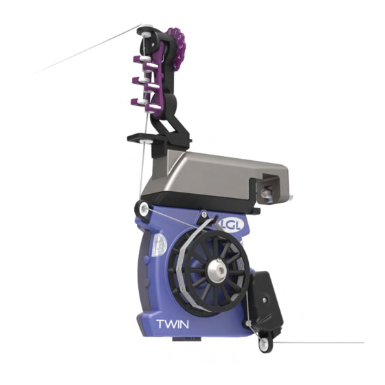
- Page 8 1 - GENERAL INFORMATION 1.1 MAIN PARTS – CONTROL AND ADJUSTMENT POINTS Main parts: 1 • TENSIONER 7• LOAD CELL 2• SEPARATING PIN 8• YARN GUIDE CERAMIC 3• SEPARATION CONTROL SCREW 9• CONNECTOR 4• YARN FEEDING WHEEL 10• CLAMP 5• ALARM LIGHTS 11•...
- Page 9 1 - GENERAL INFORMATION The TWIN device is available in 2 different versions, one featuring a yarn recovery option (up to 20 cm), and another version which does not feature this option (the yarn feeding wheel only turns forward). Version with yarn recovery...
- Page 10 It can be used on knitting machines or textile machines in general to monitor elastic and non-elastic yarns. The main feature of TWIN is that it is very compact in size and can be installed in clusters/ batteries with a cascade chain connection, which provides savings in term of and wiring, and an easier installation.
- Page 11 • Addressing option via an external “E2PROM” prenumbered (T-Conn) or without “T-Conn” via “LGL3A” (Automated Assisted Addressing) • LGL Can Open Addressing extended to 999. • Signalling interface for user: Green LED and orange LED. • Key interface for user: BLUE key (ON/OFF) and BLACK key (CONFIG).
- Page 12 2 - INSTALLATION AND START-UP 2.1 INSTALLATION OF YARN ACCUMULATOR N.B.: Yarn accumulators that are moved from warehouse storage into a warmer weaving mill environment may develop condensation; please wait until they are completely dry before connecting them up. Failure to do so may damage the electronic components.
- Page 13 2 - INSTALLATION AND START-UP Keep flat cable with top portion flush to ring profile. N.B.: The support ring shall be sized as follows: - Height not less than 25mm - Max thickness 10 mm 2. Place the clamp in the desired position; close the clamp grab screw until the strip is punctured, taking care to have the clamp connector guide (A) match the seat on the plate.
- Page 14 2 - INSTALLATION AND START-UP 2.2 CONNECTIONS Each TWIN device is equipped with an “Receptacle” input connector (A) and a “Header” output connector (B) having the same “pinout”, which enables a cascade connection of several devices in a “battery” embodiment.
- Page 15 +Vdc Alim. 2.2.2 Connection problems The TWIN devices are designed to ensure that, in the event of connection errors, they are not damaged. Of course if voltage ratings applied range within the limits set for the device. The main connection problems are listed below.
- Page 16 2 - INSTALLATION AND START-UP 2.3 USER INTERFACE ON “BUTTONS AND LEDS The TWIN device is equipped with 2 buttons and 2 signal lights. Signal lights Buttons The upper button, blue in colour, is defined as the ON/OFF button and is used for the Turn ON/Turn OFF functions as well as for the main functions.
- Page 17 3 - START-UP AND WINDING 3.1 BASIC USE OF THE DEVICE Once turned on, the TWIN device runs an initialization and diagnostic check. If at this stage no issues are found, the device sets itself to the RUN mode. In the RUN mode the following condition will be found: •...
- Page 18 3 - START-UP AND WINDING At this point it will be possible to insert the thread into the special eyelets and wind it around the yarn feeding wheel. THREADING: Wind the yarn around the feeding wheel as shown in the figures, taking care that the first coil is run below the separation pin, whereas for the following coils the yarn shall run above the pin (A).
- Page 19 3 - START-UP AND WINDING Transition Button control from RUN to WYW Hold ON/OFF pressed for 1sec and then release it. from WYW to RUN Click on ON/OFF. from WYW to SLP Hold ON/OFF pressed for 1sec. N.B.: The device can be set to the WYW state also through a special command via the communication can bus by sending the related value to the “Command”...
- Page 20 3 - START-UP AND WINDING and then will set itself back to WYW mode to allow the yarn to be placed back on the sensor. If the calibration proves to be Incorrect, the device will set itself to the Fault mode. Transition Button control from RUN to WYW...
- Page 21 4 - PARAMETERS DESCRIPTION N.B.: It is possible to edit the various operating parameters through the interface of various devices, Computers, Tablets, KYC devices. Please refer to the specific instructions for use of the device. Here follows a description of the various parameters and the possible settings.
- Page 22 4 - PARAMETERS DESCRIPTION 4.5 “TE-TensErr” Read/Write: it is the maximum yarn tension tolerance allowed during device operation, as to the set tension. If one or both parameters between “TE-TensErr” and “TA-TimeAlr” is at 0, the alarm is disabled. 0 = disables the alarm. If >...
- Page 23 4 - PARAMETERS DESCRIPTION • 0 (default) = the TE tension error alarm is enabled soon after the RUN signal • 1 to 100 = the alarm is actuated with a delay in seconds equal to “RunAlrmDly”, see examples below. “RunAlrmDly”...
- Page 24 4 - PARAMETERS DESCRIPTION 4.12 “RL-RewLeng” Parameter used to set the yarn recovery function. Default value = 0 = recovery disabled If RL-RewLeng> 0 and the feeder is equipped with the related wheel, the yarn can be recovered. By setting a value ranging between 1 and 200, the wheel will recover this amount in millimetres.
- Page 25 5 - LED SIGNALS Below are tables providing details on the actuation and blinking modes of the LEDS as a function of the states of the device, plus additional signals related to the interaction with the user. Please note that all signals related to Can Bus failures involve the flickering of the Orange LED light.
- Page 26 6 - WARNINGS, ALARMS E FAULTS In the TWIN device failures are divided into 3 categories: Warnings, Alarms and Faults. These states can be seen from the LEDs of the device and via the Can Bus communication. Device in Warning state. Low...
- Page 27 6 - WARNINGS, ALARMS E FAULTS For further details, see tables in chapter LED signals. Via Can Bus communication an error code can be read along with the related description string. Each error code can correspond to one or more device states. The last letter (A or F) in the Error type description string indicates whether the state related to that error corresponds to an Alarm or Fault state.
- Page 28 6 - WARNINGS, ALARMS E FAULTS Error string Description State "CellOfs F" Out-of-range Cell Offset calibration fault. "CellGdn F" Out-of-range Cell Gain calibration fault. "MotLock F" Motor Lock fault. "MotIMax F" Motor I-Max fault. "MotHallS F" Analog Hall sensor signal reading Fault. High-Voltage Fault on Can Bus line (of course in the "CanBus F"...
- Page 29 They are actuated when a failure occurs that is included in the normal application operation (textile processing) and only require the user’s action to restore the normal working mode. The alarms envisaged for the TWIN device are: • OverFeed. This alarm cannot be disabled by the user.
- Page 30 6 - WARNINGS, ALARMS E FAULTS 6.2.3 Alarm Tension Error Tension error. Parameters “TE-TensErr” and “TA-TimeAlr”. It is generated when the measured tension is not within the set tolerances set for parameter “TE-TensErr” for a time defined in tenths of a second by parameter “TA- TimeAlr”. The negative tolerance is however automatically limited to 0.4g, in cases when the value set in “TE-TensErr”...
- Page 31 7 - CONVERSION TABLE 7.1 YARN CONVERSION TABLE IN THE VARIOUS COUNT SYSTEMS den Dtex Ne den Dtex Ne 18.000 48.000 10,63 550 29,76 28,35 208 79,37 18.140 10,71 48.380 28,57 50.000 19.350 11,43 29,53 200 82,68 20.000 450 500 11,81 33,07 50.800 20.320...
- Page 32 8 - SCRAPPING If you decide to scrap the machine, you need to destroy/erase all machine identification plates and related documents. If disposal is assigned to an external party, always resort to organizations duly authorized to recovery and/or disposal of the demolition materials. If you perform the disposal on your own, you need to divide the material by type and instruct authorized organizations to dispose of them according to the various waste categories.
- Page 33 DICHIARAZIONE DI CONFORMITÁ CE La macchina è un alimentatore di trama per macchine per maglieria. Produttore: L.G.L. Electronics Modello: TWIN La macchina è conforme ai requisiti essenziali delle direttive 2006/42/CE, 2014/35/UE, 2014/30/UE. Le norme armonizzate applicate sono: EN 60204-1 (2006), EN 61000-6-4 (2007), EN 61000-6-2 (2007), ISO EN 3746 (2009).
- Page 34 CE ÜBEREINSTIMMUNGS ANGABE Die Maschine ist ein Vorspulgerät für Wirkmaschinen. Hersteller: L.G.L. Electronics Typ: TWIN Die Maschine entspricht der wesentlichen Anforderungen der Richtlinien 2006/42/CE, 2014/35/UE, 2014/30/UE. Die angewendeten harmonisierten Normen sind die folgende: EN 60204-1 (2006), EN 61000-6-4 (2007), EN 61000-6-2 (2007), ISO EN 3746 (2009).
- Page 35 VERKLARING VAN CE OVEREENSTEMMING Deze machine is een inslagvoorspoelmachine voor breimachines. Merk: L.G.L. Electronics Type: TWIN De machine voldoet aan de essentiële vereisten van de richtlijnen 2006/42/CE, 2014/35/UE, 2014/30/UE. De volgende geharmoniseerde normen zijn toegepast: EN 60204-1 (2006), EN 61000-6-4 (2007), EN 61000-6-2 (2007), ISO EN 3746 (2009).
- Page 36 — SUOMEKSI — CE VASTAAVUUSTODISTUS Kone on neulekone. Merkki: L.G.L. Electronics Tyyppi: TWIN Kone on direktiivien 2006/42/CE, 2014/35/UE ja 2014/30/UE olennaisten vaatimusten mukainen. Sovelletut harmonisoidut standardit ovat: EN 60204-1 (2006), EN 61000-6-4 (2007), EN 61000-6-2 (2007), ISO EN 3746 (2009).
Need help?
Do you have a question about the TWIN and is the answer not in the manual?
Questions and answers