Advertisement
Quick Links
Advertisement

Related Manuals for Fass STK-5500


Summary of Contents for Fass STK-5500
- Page 1 INSTALLATION MANUAL STK-5500 ACCESSORY: Suction Tube Kit “SUMP”...
- Page 2 Building extremely “High-Quality” fuel products is our business. We concen- trate all of our efforts in this arena. No one else is as specialized as FASS in what we do! This is one of the ingredients to insure you are running with the “Highest-Quality”...
- Page 3 ViP FASS dealer for the installation. They are prepared to install the FASS fuel pumps with the most effi- ciency. If a situation/problem arises during the installation, they are the most pre- pared for that situation/problem.
- Page 4 STK-5500 Contents SC-5500 SP-5500 DT-1002 FL-1007 1/2” Plug SB-5500 BHF-1002 PL-1001 PL-1004 Nylon Washer SSSCP1420112 (4) BHN-1001 11107655 (10) 1/4-20x1 1/2 SHCS14Z015Z (10) Set Screw 1/4”-20 x 1 1/2” OR-223 HC-1001 OR-340Viton LW-1001 SHCS93164 OR-350Viton...
- Page 5 Step 1: Removing Fuel Sending Unit Some of the photo’s are of a different application, refer to the photos that resemble your application. A. Disconnect the vehicles battery. Remove the filler neck and overflow tubes from the truck by loosening the clamps.
- Page 6 Step 1: Removing Fuel Sending Unit D. Disconnect the factory electrical harness. E. Unbolt the tank and remove it from vehicle. Clean all fittings and save for reinstallation. F. Clean the fuel module area then remove the lock ring/nut. Note/Mark the location of the fuel sending unit in relation the top of the fuel tank fro re-installation.
- Page 7 Step 2: Preparing sump A. Locate the lowest point of the fuel tank, which is typically below the fac- tory fuel module. On some applications there is a dimple you can use for a center point reference and it has the flattest surface for sealing the sump. B.
- Page 8 Step 2: Preparing sump F. Using a 1/4 - 20 x 1 1/2” SHCS bolt the sump into place. Opposite the previously drilled hole drill an identical hole and insert bolt. This will hold the sump in place to continue the next step. G.
- Page 9 Step 2: Preparing sump K. Install the 2 set screws into the bridge L. Insert DT-1002 (draw tube) into the bridge. Position DT-1002 about 1/8” to 3/16” (approximately 2 quarters) from the surface of the sump. With the DT-1002 in proper position tighten down the 2 set screws. M.
- Page 10 Step 3: Preparing Fuel Sending Unit Some of the photo’s are of a different application, refer to the photos that resemble your application. This step is not necessary if sump is NOT going to be located below the fuel sending unit. Remove non-essential features from the center of the fuel basket.
- Page 11 Step 3: Preparing Fuel Sending Unit Using a Sharpie, mark staggered holes starting 1” from the bottom of the basket. Avoid marking holes where the factory return stacks and posts guides are located as well as where the draw tube assembly is installed.
- Page 12 TAPE ON PL-1004, FITTING IS EQUIPPED WITH THREAD SEALANT** Insert the 1/2” plug into the “R” port of the BHF-1001 Maintaining ‘FASS Return Fuel’ to Filler Neck Reroute this line to the “R” port of the BHF-1002 (bulk head Re-Routing the fitting) by removing the manifold &...
- Page 13 Step 4: Preparing BHF Assembly Drill a 1 3/8” hole where marked, catching all debris by holding a cup under the drilling site. Take any necessary steps to limit tank contamination with debris. De-burr hole and check for fit. Place the OR-223 over the BHF assembly. Then place the assembly into drilled hole.
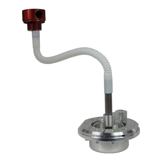
- Page 14 Step 5: re-installing Fuel Sending Unit & Connecting sump A. Attach the FL-1007 (opposite end/convoluted tube) to the DT-1002 & SB-5500 assembly using the hose clamp (HC-1001). Allow the tube to hang down for now. Attach the FL-1007 (Viton tube) to the BHF assembly using the hose clamp (HC-1001).
- Page 15 Step 5: re-installing Fuel Sending Unit & Connecting sump G. Place nylon washers onto the 1/4 - 20 x 1 1/2 SHCS’s. Recommendation: apply a small amount of gasket sealant onto the threads to help prevent any leaks. H. Install the inner and outer O-rings to the sump. Using the 1/4 - 20 x 1 1/2 SHCS’s, install sump over alignment studs, then remove the alignment studs and replace with the SHCS’s.
- Page 16 O. Using oil, push fuel line onto the push lock located at the “S” port of the BHF assembly. If returning fuel to the BHF assembly attach the FASS fuel return line to the “R” port of the BHF assembly.
- Page 17 S. Reinstall fuel tank. Torque hanger bolts to factory specifications. If need be, cover the return line with spare tubing or similar to protect fuel line from rubbing on the trimmed fiberglass shell. Route FASS fuel line to prevent pinching.
- Page 18 Sump Template...
- Page 19 NOTES...
- Page 20 NOTES...
Need help?
Do you have a question about the STK-5500 and is the answer not in the manual?
Questions and answers