
Related Manuals for Isel ICP 3020


Summary of Contents for Isel ICP 3020
- Page 1 Operating Instruction CNC compact machinery type model ICP iMC-P ICP 3020, ICP 4030 isel Germany AG Bürgermeister-Ebert-Straße 40 D-36124 Eichenzell Tel.: (06659) 981-0 Fax: -776...
- Page 2 ICP 3020 / ICP 4030 iMC-P About this manual Used shortcuts Machinery directive 2006/42/EC Used symbols You will find different symbols in this manual that signalizes important information/ facts and danger. Warning! This symbol indicates dangers that cause damages for person’s health, physical injury or death.
- Page 3 ICP 3020 / ICP 4030 iMC-P Operating instruction Copyright isel Germany AG, 2009 All rights reserved. Despite all care, printing errors and mistakes cannot be excluded. For suggestions and information on errors, we are grateful. CE mark for (completed) CNC machinery: isel CNC machinery are CE compliant and marked accordingly.
-
Page 4: Table Of Contents
Adjusting the stepper motor power amplifiers ..........27 Installation and initial operation ................30 Safety notes....................30 Preparation ....................30 7.2.1 Connections Software installation ................... 31 Operation modes ..................32 7.4.1 Using the ICP 3020 / ICP 4030 in CNC mode Seite 3... - Page 5 ICP 3020 / ICP 4030 iMC-P Operating instruction 7.4.3 Using the ICP 3020 / 4030 in DNC mode Maintenance ........................ 35 Cleaning the machine ................. 35 Lubrication ....................35 Faults ........................... 37 Accessories ......................38 Technical data ......................39 11.1 Dimensions and weight ................
-
Page 6: Introduction
ICP 3020 / ICP 4030 iMC-P Operating instruction 1 Introduction This manual contains the operation instruction for machinery of type ICP with iMC-P stepper motor control. The machine is delivered fully assembled on a pallet. In the scope of delivery of the ICP 3020 / 4030 is included: ... -
Page 7: Intended Use And Reasonably Foreseeable Misuse
ICP 3020 / ICP 4030 iMC-P Operating instruction 2 Intended use and reasonably foreseeable misuse Isel CNC machinery of type ICP are CNC controlled machinery with more than one linear axis resp. one or two optional rotation axis. The motor power amplifiers will be driven via a PC based stepper-motor-control. - Page 8 ICP 3020 / ICP 4030 iMC-P Operating instruction CNC-machine: o The CNC-machine (complete machine) is according to the type mounted on the machine tool appropriately used. That is, the concrete tool of the CNC machine specifies the intended use of the machine within the meaning of the Machinery Directive (Annex I, Section 1.1.2).
-
Page 9: Safety Instructions
ICP 3020 / ICP 4030 iMC-P Operating instruction 3 Safety instructions Do not operate the machine in a potentially explosive atmosphere The machine is fully enclosed. The transparent panes (material: polycarbonate) mounted in the machine frame resp. in the door ensure during operation of the machine (setup or working process) protection against moving machine parts as well as eventually thrown work piece fragments from the work area. -
Page 10: Occupational Safety
ICP 3020 / ICP 4030 iMC-P Operating instruction Please keep the replacement key switch under your personal check. The operator has guarantee sufficient ventilation according accruement of dust or gas, caused by the operation process of working pieces. -
Page 11: Delivery Status From The Factory (Quality Safety)
ICP 3020 / ICP 4030 iMC-P Operating instruction 4 Delivery status from the factory (quality safety) To test the machine accuracy of the CNC machine the circular form measuring system Renishaw QC10 is used. With this system will be the accuracy of axles all produced CNC machinery / CNC base machinery checked before delivery. -
Page 12: Installation And Connection Of The Cnc Machine
ICP 3020 / ICP 4030 iMC-P Operating instruction 5 Installation and connection of the CNC machine 5.1 Dimensions and space requirement The space requirement of the machine is limited to the external measurements and to sufficient room in front of the machine in order to operate and arrange the processing, plus approx. -
Page 13: Transport Of The Cnc Machine
Never loosen the fastenings of the axles or the mounting bracket, in which the transverse axis (X-fitted axis). Otherwise, the machine must be re-measured by a technician from manufacturer isel Germany AG. Place the machine on a plane and solid area. -
Page 14: Coordinate System And Reference Point
ICP 3020 / ICP 4030 iMC-P Operating instruction 5.4 Coordinate system and reference point The coordinate system of the machine is determined as shown in the figure. However, you can select (displace) the P0 work piece zero point freely via software. -
Page 15: Enclosure With Safety Interlock
ICP 3020 / ICP 4030 iMC-P Operating instruction Using corresponding holders, you can also attach many other tools, measuring instruments (laser), or other suitable equipment to the T-slot plate of the Z-axis. Use the branch box at the Z-axis for the electrical connection. -
Page 16: Assembly And Operation
ICP 3020 / ICP 4030 iMC-P Operating instruction 6 Assembly and operation On delivery: are all control elements to the security circuit of the machine control is the main spindle drive (without speed control 100-230VAC 500 – 750 W or with speed control 750W ) ... -
Page 17: Overview
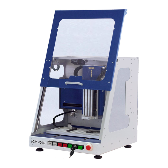
ICP 3020 / ICP 4030 iMC-P Operating instruction 6.2 Overview Z-axis (vertical axis) working tool (milling machine) tool collar Ø 43mm X-axis (transverse axis) safety hood with solenoid interlock safety glass Y-axsi (longitudinal axis) bezel with control elements machine feets (height adjustable) -
Page 18: Connectors
ICP 3020 / ICP 4030 iMC-P Operating instruction 6.3 Connectors 6.3.1 Connectors on the back side of the machine number designation description SubD-9-pin plug Communication between stepper motor control and control PC is realized via a serial interface (RS232). Use the delivered communication (null modem) cable for connection. A software protocol realizes the faultless transmission of the ASCII characters. -
Page 19: Control Elements On Front Side Of The Machine
ICP 3020 / ICP 4030 iMC-P Operating instruction 6.3.2 Control elements on front side of the machine notation description Turns off the power supply for the motor power amplifiers and the working spindle in case of any danger. This means dangers for the users health or machine safety. The integrated security circuit is applicable category 2 with PL c according to EN 13849-1. - Page 20 “4 – operation mode switch“ are complied. An enable for opening of the cover or safety door is signalized by a white lighted cover button. ACK (ACKnowledge) This button has no function on the machine ICP 3020 / ICP 4030. page 19...
-
Page 21: Stepper Motor Control Assembly
ICP 3020 / ICP 4030 iMC-P Operating instruction 6.3.3 Stepper motor control assembly page 20... -
Page 22: Connectors Of The Stepper Motor Control
ICP 3020 / ICP 4030 iMC-P Operating instruction 6.4 Connectors of the stepper motor control 6.4.1 Access to stepper motor control and their components To get to the connectors of the stepper motor control, you do the following: Unplug the main power supply plug! -
Page 23: Connectors
ICP 3020 / ICP 4030 iMC-P Operating instruction 6.4.2 Connectors Stepper-Motor – motor connector X-, Y-, Z-, A-axis, Sub-D-9-pin Socket Connector for motor modules (CNC axis). Connect / disconnect the Sub-D plug only if the controller is switched off. Ignoring this instruction can lead to damage the motor cable or stepper motor amplifier. - Page 24 ICP 3020 / ICP 4030 iMC-P Operating instruction Use external emergency stop: pin 5 and 6 bridged pin 7 and 8 bridged The length of the connection cable for the external emergency stop button must not more than 5m. Use external power button: pin 1 and 2 bridged...
- Page 25 ICP 3020 / ICP 4030 iMC-P Operating instruction The binary user inputs 1 – 8 must be wired as shown opposite. The load of the controller internal 24V power supply unit amounts on 1-active state 4 mA per input. Output - digital outputs, 8-pin connector The controller has 8 digital user outputs.
- Page 26 Cover - Sub-D9-pin connector This connector is used to integrate a solenoid interlock to the security circuit of the controller. On isel machines the solenoid interlock is realized by a switch of type: SCHMERSAL EX-AZM 170-02ZK-24V Only this type interlocks or interlocks with the same functionality have to be used.
- Page 27 ICP 3020 / ICP 4030 iMC-P Operating instruction Spindle - 100 - 230V output, three-pin-plug Use this output connector to directly plug a working spindle or a frequency inverter with a speed controlled working spindle (e.g. iSA750). According to the working spindle type you...
-
Page 28: Adjusting The Stepper Motor Power Amplifiers
6.5 Adjusting the stepper motor power amplifiers The CNC machine ICP 3020/4030 iMC-P has four stepper motor power amplifiers MD24. Settings for rated current, step resolution and current reduction takes place by the DIP- switch on the top side of the amplifiers case. - Page 29 ICP 3020 / ICP 4030 iMC-P Operating instruction Open the machine housing and the control case Remove the cover on the back side of the machine. After that, remove the cover of the stepper motor control (see chapter 6.4.1). The stepper motor amplifiers are arranged side by side.
- Page 30 ICP 3020 / ICP 4030 iMC-P Operating instruction current reduction (DIP-switch 4) Use the DIP switch 4 to set the automatic current reduction. If the DIP switch is set to ON the automatic current reduction is deactivated. DIP switch in state OFF means that the current is set to 50% of the motor current if the motor standstill.
-
Page 31: Installation And Initial Operation
ICP 3020 / ICP 4030 iMC-P Operating instruction 7 Installation and initial operation 7.1 Safety notes Please note the technical data of the machine as well as the terminal assignment on chapter Fehler! Verweisquelle konnte nicht gefunden werden.. Ignoring the safety precautions could result in injury to persons and goods by mechanical or electrical influences or the failure of the device. -
Page 32: Software Installation
ICP 3020 / ICP 4030 iMC-P Operating instruction First initial operation Do the following steps to set up the machine: Switch on the machine via the main power supply switch on the back side of the machine Check if emergency stop switch is pulled out and key switch is in position AUTO ... -
Page 33: Operation Modes
Software PALPC 2.1 is used for programming and download of user programs into the flash memory of the machines controller 7.4.1 Using the ICP 3020 / ICP 4030 in CNC mode The CNC mode (automatic mode = CNC mode) is the program controlled mode of the stepper motor control of the machine. - Page 34 ICP 3020 / ICP 4030 iMC-P Operating instruction PALPC settings and machine test Control type Select as control type compact control IMC4-M / I-MC-P RS232 settings Select your available COM port an transfer rate 19200 baud Control settings Fill in 800 steps / rev...
-
Page 35: Using The Icp 3020 / 4030 In Dnc Mode
CNC mode you will find in the Remote operation manual /3/. Using digital inputs and outputs and signalization interface in Remote/ProNC Machinery of type ICP 3020 / ICP 4030 iMC-P have each 8 digital inputs and outputs which can be used by the user. -
Page 36: Maintenance
ICP 3020 / ICP 4030 iMC-P Operating instruction 8 Maintenance Open the hood before switching off the machine using the mains switch. After this, this is no more possible. Switch of the main switch before any cleaning and any maintenance. - Page 37 ICP 3020 / ICP 4030 iMC-P Operating instruction To lubricate the X-axis, move the sledge to the left*. Remove the plastic plug on the left side of the machine and lubricate through the now visible lubricating nipple. You access the shaft guides again through the sealing lips.
-
Page 38: Faults
ICP 3020 / ICP 4030 iMC-P Operating instruction 9 Faults Error reason solution net input plug not connected check net input cable connection machine will not turn on main switch not switched on switch on main switch remove net input plug,... -
Page 39: Accessories
ICP 3020 / ICP 4030 iMC-P Operating instruction 10 Accessories Matching for each ICP 3020 / 4030 CNC machine, you can order the following accessories: clamping set (clamp lever SH1,SH2, 2 stop rails, hexagon socket wrench) additional mounting material for T-groove panel ... -
Page 40: Technical Data
ICP 3020 / ICP 4030 iMC-P Operating instruction 11 Technical data 11.1 Dimensions and weight data ICP 3020 ICP 4030 dimensions W x D x H [mm] 610 x 650 x 715 780 x 835 x 810 movement area X axis... -
Page 41: Declaration Of Conformity For Complete Machinery
ICP 3020 / ICP 4030 iMC-P Operating instruction 12 Declaration of conformity for complete machinery EC Declaration of Conformity corresponding Machinery Directive 2006/42/EU, Annex II A The manufacturer isel Germany AG Bürgermeister-Ebert-Straße 40 D-36124 Eichenzell declares hereby, that the following products... -
Page 42: Bibliography
ICP 3020 / ICP 4030 iMC-P Operating instruction 13 Bibliography MD24 MD28 micro stepping driver: Instruction Manual / hardware description MD24 / MD28 ; isel Germany AG, 01/2010 PAL-PC: programming instruction: Software manual PALPC; isel automation 06/2004 Remote: Operation and output program for ISO-, NCP- and CNC files: Software manual Remote;... -
Page 43: Index
ICP 3020 / ICP 4030 iMC-P Operating instruction 14 Index movement area ..............37 accessories................36 ACK ..................18 null modem cable ..............29 air pressure ................36 Analog - Out ................. 24 Operation mode switch ............18 operation modes ..............31 CE marking ................ -
Page 44: Appendix
ICP 3020 / ICP 4030 iMC-P Operating instruction 15 Appendix Service supply note Sender company ______________________________________________ customer no ______________________________________________ ______________________________________________ contact person / dept. ______________________________________________ phone _______________________fax____________________ postal address ______________________________________________ return to ______________________________________________ invoice-no. quantity item-number designation delivery note-no. serial-number... - Page 45 Product sent in without paid transportation charges cannot be accepted for organizational reasons. 7.) Sales conditions, delivery conditions and terms of payment As for the rest, the sales conditions, delivery conditions, and terms of payment of isel Germany are valid without change. page 44...
Need help?
Do you have a question about the ICP 3020 and is the answer not in the manual?
Questions and answers