Table of Contents
Advertisement
Quick Links
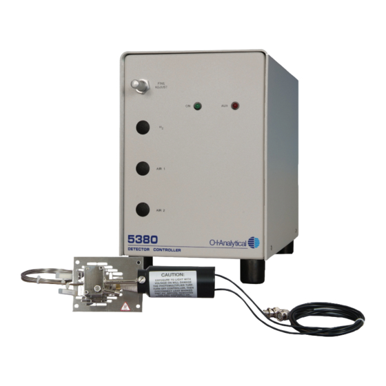
Model 5380 Pulsed Flame
Photometric Detector (PFPD)
Operator's Manual
A D
8 0
5 3
R
O
C T
T E
D E
151 Graham Road · P.O. Box 9010 · College Station, Texas 77842-9010 USA
Toll-Free: (800) 653-1711 • Tel: (979) 690-1711 • FAX (979) 690-0440 • www.oico.com
N E
X
A U
F I
S T
J U
O N
2
H
1
R
A I
2
R
A I
E R
L L
R O
N T
C O
Advertisement
Table of Contents

Summary of Contents for OI Analytical 5380
- Page 1 Model 5380 Pulsed Flame Photometric Detector (PFPD) Operator’s Manual 151 Graham Road · P.O. Box 9010 · College Station, Texas 77842-9010 USA Toll-Free: (800) 653-1711 • Tel: (979) 690-1711 • FAX (979) 690-0440 • www.oico.com...
- Page 2 Notice The information contained in this document may be revised without notice. OI Analytical shall not be liable for errors contained herein or for incidental, or consequen- tial, damages in connection with the furnishing, performance, or use of this material.
- Page 3 OI Analytical at the expense of the purchaser. Parts, labor, and return shipment to the customer shall be at the expense of OI Analytical.
-
Page 4: Table Of Contents
Secondary WinPulse Screens ................22 Chapter 4: Installation Installing the Model 5380 PFPD Assembly ............ 29 Installing the Model 5380 PFPD in the Agilent 6890 Valve Box ....32 Installing the Model 5380 Detector Controller ..........35 Installing the Pneumatics ................. 36 Preparing the PFPD for Operation .............. - Page 5 Chapter 8: Replacement Parts Replacement Parts ..................91 Chapter 9: Glossary Glossary ......................95 Bibliography Bibliography ....................99 Appendix A Photomultiplier Tube and Filter Configurations ..........101 Appendix B Definition of Detectivity ................103 Appendix C Dual Gate Capability and Calculation of Alpha ..........105 Appendix D Noise Sources and Output Signal Optimization Guide .........
-
Page 6: Chapter 1: Introduction
OI Analytical’s Model 5380 Pulsed Flame Photometric Detector (PFPD) is the latest advance in flame photometric detector design, optimized for the selective detection of sulfur, phosphorus, and other compounds. The Model 5380 PFPD is protected under U.S. Patent #5,153,673 and international patents issued to Aviv Amirav, Tel Aviv University, Israel. - Page 7 Figure 1.3 provides a flow diagram of the pneumatic system. Three manual or electronic gas flow controllers enable the operator to adjust the flow rates of H and air in the combustor gas and wall gas mixtures. The H and Air 1 control Model 5380 PFPD Operator’s Manual Rev. 3.1...
- Page 8 Air 1 Air IN Air 2 Wall Gas (WALL) + Air 1 + Air 2; Air rich) connects to upper gas line on detector base Figure 1.3. Model 5380 PFPD Pneumatics Flow Chart Chapter 1 Introduction...
- Page 9 However, the sulfur emission reaches its maximum 5–6 ms after the background emission is nearly terminated. Thus sulfur and phosphorus have chemiluminescence lifetimes sub- Phosphorus Carbon Sulfur Figure 1.4. Carbon, Phosphorus, and Sulfur Emission Lifetimes Model 5380 PFPD Operator’s Manual Rev. 3.1...
-
Page 10: Features
The operator’s ability to optimize the operation of the PFPD is facilitated by the ® use of WinPulse, a Windows -based software package developed by OI Analytical. WinPulse permits the operator to set up and optimize all of the PFPD’s operating parameters. After these parameters have been uploaded to the Detector Controller, the software is no longer required for the continued operation of the PFPD. -
Page 11: Specifications
Temperature: 10°–40°C (Operating) -20°– 65°C (Nonoperating) • Altitude: Maximum 2,000 m Controller Dimensions • 8.75" H x 6" W x 13" D • 22.2 cm H x 15.2 cm W x 33 cm D Model 5380 PFPD Operator’s Manual Rev. 3.1... - Page 12 Controller Power Requirements • 115/230 VAC, 50/60 Hz • Fuse rating: 115 VAC (±10%) - 1A Type T; 220/230/240 VAC (±10%) - 1/2A Type T Hardware Requirements for Running WinPulse • Pentium/100 MHz IBM-compatible platform (minimum) • VGA monitor (or higher) •...
-
Page 13: Compliance And Safety Information
CISPR 11: 1990/EN55011 (1991) EN50082-1: 1992 The Model 5380 PFPD has been designed and tested in accordance with recog- nized safety standards and designed for use indoors. Using the instrument in a manner not specified by the manufacturer may impair the instrument’s safety protection. - Page 14 General Precautions • This unit must be supplied with a grounded receptacle. • Disconnect the AC power cord before removing any covers. • Replace or repair faulty or frayed insulation on power cords. • Perform periodic leak checks on supply lines, fittings, and pneumatic plumbing. •...
- Page 15 Warning/Caution, see accompanying instruction for more information. Indicates a hot surface. Indicates hazardous voltages and risk of shock. Indicates earth (ground) terminal. Indicates the OFF position on the power switch. Indicates the ON position on the power switch. Model 5380 PFPD Operator’s Manual Rev. 3.1...
-
Page 16: Chapter 2: Description Of Components
HV Cable (SHV connector) connects to the PMT HV (high voltage) connector on the back of the Model 5380 Detector Controller. Ignitor Cable connects to the ignitor connector on the back of the Model 5380 Detector Controller. Signal Cable (BNC connector) connects to the PMT signal connector on the back of the Model 5380 Detector Controller. -
Page 17: Model 5380 Detector Assembly - Exploded View
Mounting Gas Lines Plate Figure 2.2. Model 5380 Detector Assembly - Exploded View Aluminum Washers create a gas seal between the detector cap and the detector body and between the detector body and detector base. Combustor is a transparent quartz tube within which the GC column effluent combusts. - Page 18 Detector Cap serves to provide an attachment for the ignitor assembly and pro- vides the path to the exhaust vent. Flame Arrestor prevents the flame from propagating out through the vent. Gas Lines are connected to the detector base. The lower gas line (COMB) pro- vides the hydrogen-rich combustor gas that sweeps out the combustor base.
-
Page 19: Model 5380 Detector Controller - Front View
Air 1 Flow Controller Air 2 Flow Controller Figure 2.3. Model 5380 Detector Controller - Front View Air 1 controls the air flow to be added to the combustor. Air 2 controls the air supply to the external wall of the combustor and ignitor volume. -
Page 20: Model 5380 Detector Controller - Back View
Ignitor Connector Power Receptacle Power Switch Figure 2.4. Model 5380 Detector Controller - Back View Air Inlet Connector connects the air supply to the Detector Controller. Channel 1 Connector (BNC connector) connects the cable that transmits the channel 1 output signal from the Detector Controller to the data handling device. - Page 21 Note: The Combustor Gas, Wall Gas, H Inlet, and Air Inlet Connectors do not occur on Detector Controllers used in conjunction with Agilent 6890 GCs that are fitted with an internal electronic pressure controller. Model 5380 PFPD Operator’s Manual Rev. 3.1...
-
Page 22: Chapter 3: Introduction To Winpulse
Chapter 3 ™ Introduction to WinPulse This chapter describes the features of the WinPulse software developed by OI Analytical to set up and optimize all of the PFPD’s operating parameters. WinPulse is Windows-based and allows the operator to easily observe the amplitude and lifetime of the chemiluminescence emissions resulting from the combustion of the analyte in the PFPD. - Page 23 Allows specification of the Directory and File Name to Information store current raw output data. The Record button is used to initiate and stop the data record. This feature allows data segments to be stored at any time. Model 5380 PFPD Operator’s Manual Rev. 3.1...
-
Page 24: Winpulse Menu System
WinPulse Menu System The menus and screens have been organized for efficiency, with the most used functions being logically grouped together. All of WinPulse’s functions can be accessed by navigating these menus. Table 3.1 shows the complete menu/submenu structure for WinPulse. These menus are accessed from the Main Screen. Table 3.1. -
Page 25: Menu Features
For more information, see “Gate Parameters Screen” in this chapter. Board/Channel Accesses the Board/Channel Param- eters screen, which is used to set board/channel parameters. For more information, see “Board/Channel Parameters Screen” in this chapter. Model 5380 PFPD Operator’s Manual Rev. 3.1... - Page 26 Events Menu Set Timed Accesses the Timed Events Events screen. The clock for the timed events is initiated by the remote start in the Detector Controller that is activated by a contact closure supplied by either the GC or remote start switch. Commands Menu Reset PFPD Resets the Detector Controller clock...
-
Page 27: Secondary Winpulse Screens
The list of available modes also includes operator defined modes (UD1 through UD5). These modes can be selected for analytes other than those included in the list. Model 5380 PFPD Operator’s Manual Rev. 3.1... - Page 28 Start and Stop Specifies the integration gate Start and Stop times (in ms from the start of each pulse). To maximize the selectivity of the PFPD for the specified mode, the Start and Stop times should be set to incorporate as much of the emission time domain of the selected mode as possible, and minimize overlap with the emission time domain of other modes detectable with the optical filter used.
- Page 29 PMT voltage. (Noise usually increases as PMT voltage is raised above some value.) Ignitor Current Sets the current required to provide sufficient power to the ignitor for reliable flame initiation (0.0–3.30 A; 2.6–2.8 A is typical). Model 5380 PFPD Operator’s Manual Rev. 3.1...
- Page 30 Trigger Level Sets the current being generated by the PMT at which a pulse is detected. The range for the trigger level is 10–2000 mV; default is 100 mV. The actual trigger level is not critical, but it must be set high enough to avoid the intermittent left/right shifting of the emission (“gate jitter”).
- Page 31 Start Time Time in minutes from the start of the analytical run for starting the associated event. The time must be greater than or equal to 0.01 minute. Model 5380 PFPD Operator’s Manual Rev. 3.1...
- Page 32 Event Timed events that can be selected from a list by clicking on the down arrow next to the Event field. Scroll down through the list until the desired event is located and then click on it. Figure 3.4 shows an example of each event that can be selected. The selected events will be initiated at the specified times.
- Page 33 Change Modifies current timed event without adding a new mode to the Event List. Delete Deletes the selected timed event. Model 5380 PFPD Operator’s Manual Rev. 3.1...
-
Page 34: Chapter 4: Installation
In Chapter 2, the names and functions of the various components of the Model 5380 PFPD were defined. These names are used in this chapter to refer to compo- nents involved in the installation of the Model 5380 PFPD onto a Hewlett-Packard gas chromatograph (GC). - Page 35 After cutting out this hole, replace the insulation plug in its original position in the detector port. Metal Cover 1" Hole (cut for installation) Insulation Plug Plastic Cutouts Oven Wall Insulation Figure 4.1. Preparing the GC Detector Port Model 5380 PFPD Operator’s Manual Rev. 3.1...
- Page 36 Rear Detector Front Detector Position Position Remove Remove 0.853" 0.705" 5.41" 1.78" (±0.050) 3.145" Figure 4.2. Preparing the GC Top Right Cover 10. Install the appropriate analog interface boards (if required) into the GC (see the Agilent 6890 Series Gas Chromatograph Operating Manual). Mounting the PFPD on the GC 1.
-
Page 37: Installing The Model 5380 Pfpd In The Agilent 6890 Valve Box
Installing the Model 5380 PFPD in the Agilent 6890 Valve Box Following are instructions for installing the Model 5380 PFPD in the Agilent 6890 GC valve box area. The valve box sits on top of the Agilent 6890 and contains the valves and plumbing, heated zones, sensors, and insulation. - Page 38 Valve Box Heater Sensor Connector Figure 4.4. Valve Box Plate 3. Place a paper towel or tissue paper on the floor of the GC oven. From inside the oven, cut away the insulation covering the front valve port (see Figure 4.5).
- Page 39 #280834; Agilent G1530-60660) are needed. See the Agilent 6890 GC Service Manual for instructions on installing these items. 10. Pack the insulation around the detector base to minimize the dead space and heat loss. Figure 4.6. Valve Heater Driver Model 5380 PFPD Operator’s Manual Rev. 3.1...
-
Page 40: Installing The Model 5380 Detector Controller
Installing the Model 5380 Detector Controller Setting up the Detector Controller 1. Set the Detector Controller next to the GC. Since the detector ports in most GCs are located on the right side, the Detector Controller should be placed to the right of the GC. -
Page 41: Installing The Pneumatics
(PCM) in the back of the Agilent 6890 Detector Control- GC and are operated through the GC’s electronic pressure controller (EPC). ler must not exceed 90 psig. Follow the relevant method for setting up the pneumatics configuration in your GC. Model 5380 PFPD Operator’s Manual Rev. 3.1... - Page 42 Pneumatics in Detector Controller Housing - Manual Gas Flow Control 1. The Detector Controller requires a well-regulated pressure supply of H air. Pressures in the 50–70 (maximum 90) psig range are acceptable. 2. Shut off all gas supply lines to be used for the PFPD’s pneumatic system. 3.
- Page 43 PFPD (see Chapter 5). 18. Detach the flowmeter, remove the barbed fitting, and replace the flame arrestor in the detector cap. Model 5380 PFPD Operator’s Manual Rev. 3.1...
- Page 44 The pressure control manifold is the gas flow control device between the main gas source and the PFPD. The preferred gas supply option for the Model 5380 PFPD is the OIM gas flow module (Part #285049), which is mounted in the back of the Agilent 6890 GC in one of the pneumatics carrier ports marked “Front Detector”...
- Page 45 WALL. Make sure that the gas lines are pushed into the union fitting as far as they will go before tightening the nuts onto the union fitting. Securely tighten the nuts using a T/qy" wrench. Model 5380 PFPD Operator’s Manual Rev. 3.1...
- Page 46 WALL Gas Line OIM Gas Union Fitting Outlet Block Fine Adjust Needle Valve To COMB Fitting on Bottom of Needle Valve Needle Valve Bracket Figure 4.9. Needle Valve Assembly and OIM Gas Outlet Block Assembly 17. Using needle-nosed cutters, remove the appropriate detector cutout from the top back panel of the GC.
- Page 47 AIR 1 label to the left of the AUX 4 connector, and the AIR 2 label to the left of the AUX 5 connector on the front of the Auxiliary Pressure Control Manifold (see Figure 4.10). Model 5380 PFPD Operator’s Manual Rev. 3.1...
- Page 48 Air 2 Gas Line Gas Line Air 1 Gas Line Gas Outlet Block #251900 Gas Inlets Outlet Block Screw #185561 Ribbon Cable WALL Gas Lines Fine Adjust Gas Out 3 = H Needle Valve 3 4 5 4 = Air 1 5 = Air 2 COMB COMB...
- Page 49 21. Replace the flame arrestor located on top of the detector cap with the barbed can distort the fitting (Part #202077) included in the PFPD Start-up Kit. Attach a gas flow- needle valve’s meter to the barbed end of the fitting. seal and make it unreliable. Model 5380 PFPD Operator’s Manual Rev. 3.1...
-
Page 50: Preparing The Pfpd For Operation
Preparing the PFPD for Operation To use the Model 5380 PFPD, the PFPD assembly must be disassembled to install the GC column and combustor. Depending on the element to be analyzed, it may also be necessary to change the optical components. The steps necessary for each of these operations are described below. - Page 51 Mounting Screws Aluminum Washer #295295C #288050 Combustor Sleeve #283093C Heater Cable Combustor Support Detector Base #280461C (2 mm) or #280453C (3 mm) Combustor Support Washer Gas Lines #288076 Figure 4.11. Model 5380 PFPD Assembly Model 5380 PFPD Operator’s Manual Rev. 3.1...
- Page 52 Protective Sheath Combustor Combustor Extraction Tool Figure 4.12. Extractor Tool 6. Lift off the detector body and place it on a clean, lint-free lab tissue. 7. Take care not to dislodge the large aluminum washer (Part #288050) loosely attached to either the bottom of the detector body or to the top of the detector base.
- Page 53 0.5 mm to 1.5 mm above the top of 0.5–1.5 mm Combustor the combustor support. Support Note: For optimal performance, the column must be 0.5–1.5 mm above the combustor support. Figure 4.14. Combustor Assembly Model 5380 PFPD Operator’s Manual Rev. 3.1...
- Page 54 Installing the GC Column With the Column Positioning Tool Following are instructions for installing the GC column into the Model 5380 PFPD using the new PFPD column positioning tool (Part #318949). This tool simplifies column installation and minimizes the possibility of creating performance prob- lems during column installation.
- Page 55 4 mL/min, to reduce the sufur quenching that is caused by a large flux of co-eluting hydrocarbons, or when sufur is detected simultaneously with other elements that need to be optimized. Model 5380 PFPD Operator’s Manual Rev. 3.1...
- Page 56 1. If the large aluminum sealing washer between the detector base and body was dislodged during disassembly, place a new aluminum washer (Part #288050) on the detector base (see Figure 4.6) using clean metal forceps. 2. Carefully place the detector body onto the detector base. Use the central hole in the detector body to guide the detector body over the combustor support and sleeve.
-
Page 57: Installing The Winpulse Software
[Tab]. Do not click on Next until after all the required information has been entered). 5. For proper operation, it is important that the serial port in the computer be of adequate speed. The minimum specification is a 16550 buffered UART, 38.4 K baud rate. Model 5380 PFPD Operator’s Manual Rev. 3.1... -
Page 58: Chapter 5: Operation
Chapter 5 Operation This chapter describes how to operate the Model 5380 PFPD for GC analyses. Starting the PFPD System Once the PFPD assembly, Detector Controller, pneumatics, and WinPulse are installed, and all of the necessary electronic connections have been made, the system is ready to be started. - Page 59 WinPulse has already been activated, an alternative measure is to set the value in the Ignitor Current box on the Boards/Channel Parameters screen to 0.0 and click on the Apply button.) • Check gas connections for leaks and verify initial gas settings. Model 5380 PFPD Operator’s Manual Rev. 3.1...
- Page 60 • Restart the ignitor by turning on the power supply to the PFPD. (If WinPulse has already been activated and the power supply is still on, the ignitor can also be restarted by setting the Ignitor Current to 3.3 A in the Board/Channel Parameters screen.) Reset the ignitor current to 2.8 A once a regular pulse has been obtained.
-
Page 61: Optimizing The Combustor Flow
/Air 1 mixture affects the height of the second peak. Peak 1 (Detector Cap) Peak 2 (Combustor) Spike 1 (Detector Cap) Spike 2 (Top of Combustor) Spike 3 (GC Column) Figure 5.1. Primary Peaks and Secondary Spikes of PFPD Fluorescence Model 5380 PFPD Operator’s Manual Rev. 3.1... - Page 62 Small spikes to the left of the first peak result from luminescence created by the flame propagation through the tortuous pathway within the detector cap. A spike between the first and second main peaks is associated with termination of the flame at the top outer edge of the combustor.
- Page 63 Using a Permeation Source OI Analytical offers permeation kits for sulfur (Part #290411) and phosphorus (Part #290429) that include a permeation source and associated hardware. Installing a permeation source between the injector and the GC column or between the GC column and the PFPD facilitates delivery of a steady concentration of analyte to the combustor.
- Page 64 4. Install the end of the GC column into the other inlet of the permeation cham- ber using a reverse ferrule nut and ferrule. 5. Slowly increase the oven temperature until sufficient chemiluminescence signal is observed in WinPulse. Do not set the temperature so high that signal amplitude begins to approach the maximum signal handling capacity of the PFPD (i.e., the signal should be well below 65,000 counts in WinPulse).
- Page 65 2 flow rate. For a significant change of the PFPFD pulse rate, all the gas flow rates need to be proportionally increased or decreased as the pulse rate linearly depends on the total gas flow. Model 5380 PFPD Operator’s Manual Rev. 3.1...
- Page 66 Using Multiple Manual Injections If a permeation device is not available, making multiple isothermal injections of a test analyte can also be used to optimize the PFPD’s detectivity. 1. Inject a sample containing the analyte of choice into the GC column. With most solvents, the flame may not propagate when the solvent elutes from the column due to excessively rich fuel conditions, but as the solvent concentra- tion decreases in the PFPD to a sufficiently low level, the flame will be...
-
Page 67: Optimizing Pfpd Detectivity And Selectivity
If the gas flows are properly optimized, the “tail” of the phospho- rus emission should extend out to 12–15 ms (see Figure 5.4). 6. Optimize the PMT voltage and trigger level. See step 14 of “Starting the PFPD System” in this chapter. Model 5380 PFPD Operator’s Manual Rev. 3.1... - Page 68 Recommended Phosphorus Gate Figure 5.4. Phosphorus Emission and Gate Settings for Maximizing Phosphorus (Note: The PMT voltage was set to 400 V.) Maximizing Sulfur Response Sulfur exhibits a quadratic chemiluminescence response (i.e., the response is a function of the square of the sulfur concentration). For detecting trace levels, the objective is to increase sensitivity by maximizing the sulfur concentration within the combustion just as the flame begins to propagate through it.
- Page 69 1. Decrease sensitivity by decreasing the PMT voltage, range, and/or amplitude settings in WinPulse. 2. If the emission starts to collapse (i.e., does not extend beyond 20 ms) when using the 2-mm combustor, one option is to replace it with a 3-mm combustor. Model 5380 PFPD Operator’s Manual Rev. 3.1...
- Page 70 3. Set the detector temperature to 250°C. Higher temperatures can be used for some applications if needed, resulting in a small decrease in sensitivity. 4. Set the combustor gas composition to the optimum H -rich mixture. 5. Set the fine adjust needle valve so that the needle valve is half a turn counter- clockwise from the point in which the PFPD goes out of tick-tock.
- Page 71 Gate A Start Time in the Gate Parameters screen to 6–8 ms) to minimize the hydrocarbon and sulfur response overlap. Due to the long time domain of the sulfur emission, a correctly delayed gate can virtually eliminate carbon interferences without using dual gate techniques. Model 5380 PFPD Operator’s Manual Rev. 3.1...
- Page 72 Maximizing Phosphorus to Sulfur Selectivity 1. Use an optical filter in the PMT assembly that is optimal for detecting phos- phorus (see Appendix D). This will minimize the sulfur response. However, if another filter that allows detection of both phosphorus and sulfur is in place, the following steps will still increase phosphorus selectivity.
-
Page 73: Minimizing Quenching
A lower temperature will increase the sulfur detectivity. 5. From WinPulse, set the gate start to 5 ms and the gate stop to 24.9 ms. Model 5380 PFPD Operator’s Manual Rev. 3.1... -
Page 74: Testing The Pfpd Performance
Testing the PFPD Performance The performance of the PFPD should be tested only after it has been optimized for the desired detectivity and selectivity. This presumes that suitable filters have been installed, the PMT voltage has been set correctly for detecting the analyte, the H to Air 1 flow ratio and integration gate settings have been optimized, and the correct detection mode has been specified and selected in the WinPulse software. - Page 75 (See Appendix A for calculation of detectivity for sulfur and phosphorus.) Figures 5.8 and 5.9 provide a chromatographic example of a standard test for sulfur run by OI Analytical. The following specifications were used to obtain this output. •...
-
Page 76: Recording Winpulse Files To Be Viewed With Pfpdview
WinPulse data can be recorded in a format that can be viewed and manipulated in PFPDView. PFPDView is a software option package for the Model 5380 PFPD. This program can be used to reprocess (post-run) either portions of or an entire chromatographic run under different PFPD operational parameters without the need for rerunning the chromatographic analysis. - Page 77 WinPulse files, go to the Utilities menu and and select Set Prefer- ences. Set the maximum data file size for a run. The data file is automati- cally closed when the maximum limit for the data file is met. Model 5380 PFPD Operator’s Manual Rev. 3.1...
-
Page 78: Chapter 6: Maintenance
(second peak) begins to “tail” excessively (i.e., beyond 6 ms from the trigger point). When conditioning a column attached to a Model 5380 PFPD, an old dirty combustor should be installed in order not to contaminate a clean combustor. - Page 79 Support Washer Gas Lines #288076 Figure 6.1. Model 5380 PFPD Assembly 5. Using the appropriate combustor extractor tool (Part #280719 for 2-mm I.D. combustor; Part #280727 for 3-mm I.D. combustor) (see Figure 4.9) and Teflon-coated forceps, carefully remove the combustor from the detector body.
- Page 80 4. Take care not to dislodge the large aluminum seal washer (Part #288050) from either the bottom of the detector body or the top of the detector base. 5. Examine the top of the column extending beyond the top of the combustor support.
- Page 81 6. Turn on the Detector Controller. Using WinPulse, reset the PMT voltage and replaced. ignitor currents to the desired set value. Model 5380 PFPD Operator’s Manual Rev. 3.1...
-
Page 82: Testing And Replacing The Ignitor Assembly
Testing and Replacing the Ignitor Assembly This section describes how to test and replace the ignitor assembly (Part #282624) if the PFPD does not ignite when appropriate gas flows and the ignitor current have been set. Figure 6.2 shows the part of the ignitor assembly housed in the detector cap. Detector Cap Flame Arrestor Attachment Nut... -
Page 83: Replacing Optical Components
PMT Cap Viton O-ring Viton O-ring PMT Mount #288084 #288068 Light Pipe Housing #284364 Optical Filter #282947(BG-12) #282921(GG-495) PMT Housing #290007(RG-695) #286096 #290015(BG-39) PMT Thumbscrew or #290031(WG-345) #177065 Figure 6.3. Photomultiplier Tube (PMT) Assembly Model 5380 PFPD Operator’s Manual Rev. 3.1... - Page 84 Replacing the Photomultiplier Tube The PMT should not need to be replaced frequently if it is handled correctly. If the output signal begins to deteriorate, increase the PMT voltage. If the required PMT voltage becomes excessively high or if the type of PMT needs to be changed, then use the following procedure.
- Page 85 Detector Controller. 11. Using WinPulse, reset the PMT voltage to its appropriate voltage (e.g., nominally 600 V). 12. Optimize the PMT voltage. See step 12 in “Starting the PFPD System” in Chapter 5. Model 5380 PFPD Operator’s Manual Rev. 3.1...
- Page 86 Replacing the Light Pipe Under normal usage conditions, the light pipe should not need to be replaced. If it is cracked or broken, use the following procedure to replace it. 1. Using WinPulse, set the PMT voltage to zero. Disconnect the PMT HV and the PMT signal cables from the back of the Detector Controller.
-
Page 87: Cleaning The Model 5380 Pfpd
Cleaning the Model 5380 PFPD The following procedures can be used for cleaning the various components, tools, and optics of the Model 5380 PFPD. Cleaning Optical Components Optical components consist of the light pipe, optical filter, and the PMT window (face of the PMT). - Page 88 Cleaning the Detector Cap, Body and Base, and Combustor Support OI Analytical rigorously cleans and bakes these parts prior to shipping to remove all traces of machining oils. Normal contamination due to handling, dust, or contact with dirty surfaces can be readily removed by using organic solvents (methanol, isopropanol, hexane, acetone, etc.).
- Page 89 Notes Model 5380 PFPD Operator’s Manual Rev. 3.1...
-
Page 90: Chapter 7: Troubleshooting
If none of the following corrective actions correct the problem(s) being experi- enced, contact OI Analytical’s Customer Service Department at (800) 336-1911 or (409) 690-1711 with the following three printouts available: 1. WinPulse screen showing a peak emission signal: To capture a peak re-... - Page 91 Examine the section of the column that Incomplete propagation extends above the combustor support. through combustor If the column’s polyimide coating has not been cleanly burnt off, add more Air 1 (or reduce hydrogen flow). Model 5380 PFPD Operator’s Manual Rev. 3.1...
- Page 92 SYMPTOM PROBABLE CAUSE CORRECTIVE ACTION PFPD quits pulsing Ignitor current is set too Increase the ignitor current to a when solvent is higher value (maximum is 3.3 A) injected and does and reset it to 3.1 A after a regular not restart after pulse is achieved.
- Page 93 If the noise is not reduced, replace the combustor. Wrong filter Verify that the correct filter is being used with the PMT. Improper gas flows Verify that the H and Air 1 flow are optimized. Model 5380 PFPD Operator’s Manual Rev. 3.1...
- Page 94 SYMPTOM PROBABLE CAUSE CORRECTIVE ACTION Improper gate values Verify that the correct mode and gate values are being used. Optimize gate and threshold (trigger) level settings in the Board/Channel Parameters window of WinPulse. Low range Increase the gain by using a lower range.
- Page 95 Notes Model 5380 PFPD Operator’s Manual Rev. 3.1...
- Page 96 Chapter 8 Replacement Parts Throughout this manual, the various components of the Model 5380 PFPD have been identified and described. This chapter is a listing of the order numbers for these components and for other replacement parts and support items. Replacement parts that OI Analytical considers expendable (XPND) or that require regular replacement are marked with an asterisk.
- Page 97 Permeation Device - Phosphorus Kit (incl. Perm Tube) 290429 Permeation Tube - Dimethyl Disulfide ......290452 Permeation Tube - Dimethyl Methyl Phosphonate ..290460 PFPDView Software ............. 312330 Power Cord - 110V for North America ......116038 Power Supply ..............284356 Model 5380 PFPD Operator’s Manual Rev. 3.1...
- Page 98 Tool - 2 mm Combustor Extractor (with Sheath) ..280719 Tool - 3 mm Combustor Extractor (with Sheath) ..280727 Tool - Allen Wrench ............284539 Tool - Teflon-Coated Forceps ........283051 WinPulse Software Kit ..........286302 ANNUAL REPLACEMENT PARTS PART # UM Req./Yr Cable - Ignitor Assembly ..........282624 Combustor - 2 mm ............282939C Combustor - 3 mm ............282913C Ferrules ................
- Page 99 Notes Model 5380 PFPD Operator’s Manual Rev. 3.1...
- Page 100 Chapter 9 Glossary The following is a glossary of the most commonly used terms and abbreviations in this manual. Term Description Analog to digital signal converter. Air 1 Flow Air flow that is split between the combustor and wall gas mixture using the fine adjust needle valve. Air 2 Flow Air flow that is delivered directly to the wall gas mixture.
- Page 101 Heater element used to ignite the flame in the detector cap. Ignitor Current Electrical current flowing through the ignitor. Interpolation Method used to obtain greater data frequency than PFPD pulse rate. Linear and spline interpolation methods are provided in WinPulse. Model 5380 PFPD Operator’s Manual Rev. 3.1...
- Page 102 Light Pipe Quartz rod that transmits chemiluminescence from combustor to the photomultiplier tube. Mode Integrator conditions specified for each signal output channel in WinPulse. Optical Filter Filter used to isolate specific chemiluminescence bands that are able to reach the photomultiplier tube. Output Zero The zero value set for the output signal.
- Page 103 PFPD. Zero The zero value set for the output signal. This is often set at some value below the lowest noise signal when the PFPD is in the tick-tock mode. Model 5380 PFPD Operator’s Manual Rev. 3.1...
- Page 104 Bibliography Patents Amirav, A., Pulsed Flame Detector Method and Apparatus. U.S. Patent 5,153,673, Israel Patent 95617, European Patent 0475250, and Japan Patent 2759854. Pulsed Flame Photometric Detection Amirav, A. and Jing, H. “Pulsed Flame Photometer Detector for Gas Chromatogra- phy.” Anal. Chem. 1995, 67, 3305–3318. [Describes improved PFPD pneumatics design, theory relating to repetition rate, dual gate techniques, and experimental information for optimizing operating parameters.]...
- Page 105 A Review.” Critical Reviews in Analytical Chemistry. 1991, 22, 183–199. Farwell, S.O. and Barinaga, C.J. “Sulfur-Selective Detection with the FPD: Current Enigmas, Practical Usage, and Future Directions.” J. Chromatographic Science. 1986, 24, 483–494. Model 5380 PFPD Operator’s Manual Rev. 3.1...
- Page 106 Photomultiplier Tube and Filter Configurations for Various Element Detection This appendix provides a list of filters that can be installed in the PMT to detect different species produced within the Model 5380 PFPD. , e l : e t : e t...
- Page 107 Notes Model 5380 PFPD Operator’s Manual Rev. 3.1...
- Page 108 Definition of Detectivity Detectivity (detectability) is determined by both the peak-to-peak noise level and the sensitivity (response) of the Model 5380 PFPD to a particular species. The following definitions of detectivity apply to both flame photometric detectors (FPDs) and pulsed flame photometric detectors (PFPDs), and are based on ASTM standards E 840-81.
- Page 109 PFPD signal output. The dual channel capability of the Model 5380 allows both the direct quadratic sulfur response and the linear square root response signals to be output simultaneously.
- Page 110 Calculation of Alpha ( OI Analytical’s WinPulse and PFPDView software programs greatly facilitate the use of the Model 5380 PFPD’s dual gate features. This appendix describes how to optimize this advanced technique. If additional information is required, call OI Analytical’s Customer Service Department at 1-800-336-1911.
- Page 111 (9–24.9 ms). Conversely, Gate B in each mode specifies the optimal gate settings for the interfering species (i.e., sulfur in the phosphorus mode and phosphorus in the sulfur mode). Reasonable Gate A start and stop times for phosphorus and sulfur are shown in Figure C.2. Model 5380 PFPD Operator’s Manual Rev. 3.1...
- Page 112 Figure C.2. Gate Parameters Window Showing Gate Settings for Phosphorus (P) and Sulfur (S) The PFPD provides two separate analog signal output channels. Thus the phospho- rus mode can be assigned to Channel 1 and the sulfur mode to Channel 2. When setting the Alpha value in each mode to zero (see Figure C.2), Channel 1 provides the output in the phosphorus mode (i.e., Gate P output), and Channel 2 provides the output in the sulfur mode (i.e., Gate S output).
- Page 113 If this is not the case, estimated Alpha values may have to be adjusted in order to adequately subtract the chemiluminescence from interfering species. Figure C.3 shows the chromatograms obtained from the two output channels using a TBP/THT test standard. Model 5380 PFPD Operator’s Manual Rev. 3.1...
- Page 114 5. Conduct a GC analysis of the test standard and obtain a chromatogram for both the Channel 1 and Channel 2 output. 6. Using the two chromatograms, select three segments that represent the follow- ing three cases (see Figure C.3). •...
- Page 115 Alpha values entered in the Gate Parameters screen will have to be adjusted to get the desired peak elimination. The use of OI Analytical’s optional PFPDView software program, which was used to generate Figure C.5, greatly facilitates the use of iteration to derive the best Alpha value.
- Page 116 Phosphorus Gate (Channel 1 Output) α Phosphorus Gate (Channel 1 Output) α = 0.370 (Sulfur peak eliminated) Sulfur Gate (Channel 2 Output) α Sulfur Gate (Channel 2 Output) α = 0.045 (Phosphorus peak eliminated) Figure C.5. Comparison of Chromatograms Derived Both With (upper) and Without (lower) the use of Calculated Alpha Values Appendix C...
- Page 117 Notes Model 5380 PFPD Operator’s Manual Rev. 3.1...
- Page 118 Optimization Guide This appendix describes the sources of noise that can affect the detectivity of the Model 5380 PFPD, and it describes how to optimize the signal output from the PFPD for optimal performance. The extent to which actual output signal noise can be detected is determined by the magnitude of other sources of noise within the detector system and the quantitation (resolution) capacity of signal converters.
- Page 119 ADC Noise The ADC (0–10 V input) used in the Model 5380 PFPD has 16 bits of resolution with an ADC count increment of 153 µV. Noise associated with the ADC usually has less than 1 bit of resolution. Caution must be used because an apparent “noise signal”...
- Page 120 Range Attenuation Maximum Current Input Voltage Output Current (µA) Resolution Resolution (pA) (1 bit) (µV) 10.000 152.59 15.259 10 µA/10V 2.500 38.15 3.815 0.625 9.45 .945 0.156 2.38 .238 0.039 0.60 .060 1.0000 15.26 15.259 1.0 µA/10V 0.2500 3.82 3.815 0.0625 0.094 .945...
- Page 121 A general rule for ensuring that there is enough resolution to observe true noise is to decrease the attenuation until the observed noise level doubles. Model 5380 PFPD Operator’s Manual Rev. 3.1...
- Page 122 Att. = 16 Range: Attentuation: 256, 128, 64, 32, 16 # DAC Steps: 6, 13 Att. = 32 Att. = 64 Autozero set too high Att. = 128 Att. = 256 Att. = 256 Range: Attentuation: 256 # DAC Steps: 2 Figure D.2.
- Page 123 (i.e. a loose column ferrule). Each of these potential problems should be systemati- cally eliminated. Furthermore, variations in the time base for pulse-to-pulse stability may, in part, be due to marginal ignition and can be eliminated by increas- ing the ignitor current. Model 5380 PFPD Operator’s Manual Rev. 3.1...
- Page 124 Appendix E Technical Assemblies Use this appendix to refer to parts and part numbers of the Model 5380 PFPD. Model 5380 Detector Assembly Ignitor Assembly Screw O-ring #282624 #295287C #288068 Flame Arrestor Light Pipe #286393 Detector Cap #282608C #246900 Light Pipe Clamp...
- Page 125 Notes Model 5380 PFPD Operator’s Manual Rev. 3.1...
- Page 126 Index ADC Noise 114 Air 1 14 Air 2 14 Air 2 Flow 95 Air Inlet Connector 15 Alpha 23, 95 Alpha Calculation 105 Attenuation 25, 27, 95 Attenuation Adjust 18 Attenuation Settings, Optimizing 114 Auto Zero 27, 95 AUX LED 14 Auxiliary EPC Manifold 42 Bibliography 99 Board/Channel 20...
- Page 127 Electrical Connections, Installing 35 Electrometer Noise 113 Electronic Pressure Control Module 96 Enable Sqrt 23 Environment 6 EPC 96 Event 27 Events Menu 21 Examining the Column Tip 74 Exit 20 Extraction Tool, Combustor 44 Model 5380 PFPD Operator’s Manual Rev. 3.1...
- Page 128 Features 5 Features, Menu 20 File Menu 20 Filter Configurations 101 Fine Adjust Needle Valve 14, 96 Flame Arrestor 13 Flow Rate 25 Combustor 2, 95 Wall 2, 98 Gas Flow Controller 4 Gas Flows 2 Gas Lines 13 Gas Requirements 7 Gate 27, 96 Gate Parameters List 22 Gate Parameters Window 22...
- Page 129 OIM Gas Flow Module 39 ON LED 14 <op> 23 Open 20 Operation 53 Optical Components Replacing 78 Optical Filter 13, 97 Replacing 80 Optimizing Detectivity 62 Optimizing for Selectivity 65 Optimizing Selectivity 62 Model 5380 PFPD Operator’s Manual Rev. 3.1...
- Page 130 Optimizing the Combustor Flow 56 Oscilloscope 55 Output Set 25 Output Signal Optimization 113 Output Zero 25, 97 Parameters Menu 20 Patents 99 Permeation Device 97 Permeation Source 58 PFID Signal Inlet 15 PFPD Orientation 51 Phosphorus Response, Maximizing 62 Phosphorus to Carbon Selectivity, Maximizing 65 Phosphorus to Sulfur Selectivity, Maximizing 67 Photomultiplier Tube 13, 97...
- Page 131 Sulfur Response, Maximizing 63 Sulfur to Carbon Selectivity, Maximizing 66 Sulfur to Phosphorus Selectivity, Maximizing 67 Temperature Limitations 6 Temperature Sensor 98 Testing Performance 68 Tick-Tock 4, 98 Timed Event 98 Timed Events Window 26 Model 5380 PFPD Operator’s Manual Rev. 3.1...
- Page 132 Toolbar 20 Transmit ALL PFPD Settings 21 Trigger Level 24, 98 Troubleshooting 85 Use DataView 21 Utilities Menu 21 Value 27 View Menu 20 View Run Log 21 Viton O-ring 13, 98 Wall Gas Connector 16 WinPulse 98 Dual Gate 105 Installing 52 Main Screen 17 Starting 53...
- Page 133 P.O. Box 9010 College Station, TX 77842-9010 Tel: (979) 690-1711 • FAX: (979) 690-0440 • www.oico.com...
Need help?
Do you have a question about the 5380 and is the answer not in the manual?
Questions and answers