
Related Manuals for Phoenix Contact PSR-TRISAFE-S


Summary of Contents for Phoenix Contact PSR-TRISAFE-S
- Page 1 INTERFACE User Manual UM EN PSR-TRISAFE-S Order No. — Device description, configuration, and startup of the PSR-TRISAFE-S safety module...
- Page 3 INTERFACE User Manual Device description, configuration, and startup of the PSR-TRISAFE-S safety module 2011-06-22 Designation: UM EN PSR-TRISAFE-S Revision: Order No.: — This user manual is valid for: Designation Order No. PSR-TRISAFE-S PSR-SCP-24DC/TS/S 2986229 -SPP-24DC/TS/S 2986232 103503_en_03 PHOENIX CONTACT...
- Page 4 Phoenix Contact accepts no liability for erroneous handling or damage to products from Phoenix Contact or third-party products resulting from disregard of information contained in this manual.
- Page 5 The receipt of technical documentation (in particular data sheets, installation instructions, manuals, etc.) does not constitute any further duty on the part of Phoenix Contact to furnish information on alterations to products and/or technical documentation. Any other agreement shall only apply if expressly confirmed in writing by Phoenix Contact.
- Page 6 Phoenix Contact. Violators are liable for damages. Phoenix Contact reserves all rights in the case of patent award or listing of a registered design, in as far as this concerns software of Phoenix Contact that meets the criteria of technicity or has technical relevance.
-
Page 7: Table Of Contents
Directives and standards ..................1-5 Intended use....................... 1-7 Documentation ....................1-8 System description .........................2-1 Method of operation and structure of the PSR-TRISAFE-S safety system ..2-1 Using the system ....................2-4 System startup and restart behavior ..............2-5 Error detection in I/O devices ................2-8 Diagnostic tools .................... - Page 8 Configuration and startup ......................5-1 Configuration overview from A to Z..............5-1 Downloading the configuration from SAFECONF..........5-4 Downloading the configuration using the IFS-CONFSTICK........5-7 Uploading the configuration from the PSR-TRISAFE-S safety module ....5-9 Function test ..................... 5-10 Startup mode....................5-11 Application examples ......................6-1 Problems and solutions ......................7-1...
-
Page 9: For Your Safety
For your safety For your safety Purpose of this manual This manual should enable the user to set up, configure, and start up the PSR-TRISAFE-S configurable safety module according to the relevant safety requirements and the risk analysis performed. The user manual is therefore designed as a complete system description, which provides... - Page 10 In the event that an error caused by reconfiguring or modifying the wiring, etc. cannot be housing removed, please contact Phoenix Contact immediately. WARNING: Repair work may not be carried out on the PSR-TRISAFE-S safety module. It is strictly prohibited to open the safety module housing. PHOENIX CONTACT...
-
Page 11: Electrical Safety
Direct/indirect contact Protection against direct and indirect contact according to DIN VDE 0100-410 must be ensured for all components connected to the PSR-TRISAFE-S safety module. In the event of an error, parasitic voltages must not occur (single-fault tolerance). Safe isolation Only use devices with safe isolation if hazardous contact voltages can occur at their connections. -
Page 12: Safety Of The Machine Or System
SAFECONF safe configuration software. Use your test report to ensure that: – The safe sensors and actuators are connected correctly in the PSR-TRISAFE-S safety application. To do this, use the "Wiring check" function in SAFECONF (see page 2-11). – The parameterization of the inputs and outputs of the PSR-TRISAFE-S safety module is correct. -
Page 13: Directives And Standards
For your safety Directives and standards The manufacturers and operators of machines and systems, in which the PSR-TRISAFE-S safety module is used, are responsible for adhering to all applicable directives and legislation. Directives and standards considered in the development and implementation of the... - Page 14 PSR-TRISAFE-S Standard Contents EN ISO 13850 Safety of machinery - Emergency stop, principles for design DIN EN 61131-2:02.04 Programmable controllers - Part 2: Equipment requirements and tests DIN EN 61131-3:02.04 Programmable controllers - Part 3: Programming languages DIN EN 61496-1:06.98...
-
Page 15: Intended Use
The safe functional blocks and functions available in the SAFECONF configuration software functions in SAFECONF for creating the safety logic are designed solely for use within the PSR-TRISAFE-S safety module and support specific safety functions. The safe functional blocks/functions can only perform their safety-related tasks within the safe control system if they have been integrated into the execution process correctly and in such a way as to avoid errors. -
Page 16: Documentation
Internet whether any changes or additions have been made to the documentation used. When working on and with the PSR-TRISAFE-S safety module, you must always keep this documentation and other items of product documentation to hand and observe the information therein. -
Page 17: System Description
– Suitable safe control devices, sensors, and actuators (depending on the application) The PSR-TRISAFE-S safety module is designed for monitoring and evaluating safety- related control devices in machines and systems (see "Intended use" on page 1-7). The safety module monitors safe control devices and safety sensors connected at its inputs, evaluates the incoming signals according to its configuration, and controls the outputs accordingly. - Page 18 PSR-TRISAFE-S Hardware: The PSR-TRISAFE-S safety module offers 20 digital safe inputs for connecting a maximum PSR-TRISAFE-S of 20 single-channel or 10 two-channel safety-related sensors and control devices. The PSR-TRISAFE-S has 4 digital safe outputs, which are semiconductor outputs (24 V DC/2 A (total current)). The outputs are designed to meet up to category 4 according to EN 954-1.
-
Page 19: Psr Tbus Din Rail Connector From Phoenix Contact
System description Communication via the The PSR-TRISAFE-S safety module is equipped with an interface for the PSR TBUS DIN PSR TBUS DIN rail rail connector. The PSR DIN rail connector from Phoenix Contact can be used to connect connector slave extension modules. Communication with these modules is then established automatically via the connector on the PSR DIN rail connector. -
Page 20: Using The System
The PSR-TRISAFE-S safety module can be configured flexibly. For the creation of the safety logic, it has safe functional blocks, which are part of the system. The PSR-TRISAFE-S can be used to implement various safety functions in different safety circuits. -
Page 21: System Startup And Restart Behavior
System startup and restart behavior Startup "Startup" refers to the behavior of the PSR-TRISAFE-S safety module after switching on (or applying the supply voltage) and following configuration via USB interface or IFS-CONFSTICK. Unless a startup inhibit is configured, the safety module starts up immediately following successful configuration (i.e., after pressing the "Confirm"... - Page 22 PSR-TRISAFE-S The table below lists the functional blocks that offer these parameters. Table 2-1 Functional blocks that support a startup inhibit/restart inhibit Functional block Function Available inhibit name EmergencyStop Emergency stop monitoring Startup inhibit Restart inhibit External device monitoring Startup inhibit...
-
Page 23: Implementing A Startup Inhibit, Restart Inhibit, And Stop Category
System description EmergencyStop PSR-TRISAFE-S Wiring the safety module with safe control devices, sensors, and actuators Reset Not-Halt E-Stop +24V 103503a005.eps Figure 2-3 Implementing a startup inhibit, restart inhibit, and stop category 0 for safe output O0 103503_en_03 PHOENIX CONTACT... -
Page 24: Error Detection In I/O Devices
PSR-TRISAFE-S Error detection in I/O devices Cross-circuit detection Cross circuits of the connected signal lines can be detected at the safe inputs. A cross circuit is an unintentional, incorrect connection between redundant circuits. Clock outputs T0 and T1 The safety module provides clock outputs T0 and T1 as an aid for detecting such a cross circuit. -
Page 25: Diagnostic Tools
For an overview of the diagnostic and status indicators, please refer to Table 3-1 on page 3-5. The SAFECONF configuration software and the PSR-TRISAFE-S safety module provide various tools that can be used to diagnose the active configuration on the safety module: –... -
Page 26: Simplified Schematic View: Hardware Diagnostics In The Event Of An Error At A Safe Functional Block
SAFECONF, in online mode (error) LEDs of inputs I0 and I1 on the safety module Safe control device, at inputs I0 and I1 of the PSR-TRISAFE-S safety module 103503a007.eps Emergency stop Reset Figure 2-6 Simplified schematic view: Hardware diagnostics in the event of an error at... -
Page 27: Simplified Schematic View: Wiring Check
A graphical link directs the user to the right position and provides a better overview of the control cabinet. Requirement: The PSR-TRISAFE-S safety module must be running. Switch the connection editor to online mode, then to startup mode. -
Page 28: Example Of An Online Tool Tip In The Event Of An Error
In online mode, when the SAFECONF configuration software reads signal values from the connection editor PSR-TRISAFE-S safety module and displays them "live" in the connection editor, the safe functional blocks indicate their status and, in the event of an error, a description of the error as a tool tip as soon as you position the cursor over the symbol for a functional block. -
Page 29: Password Protection
For the PSR-TRISAFE-S safety module: after a long period of inactivity, you must enter the controller password again in order to communicate with the safety module in SAFECONF. -
Page 30: Ordering Data
SAFECONF configuration software, configuration cable (USB), and Quick Start Guide German PSR-SAFECONF-BOX-DE 2986151 English PSR-SAFECONF-BOX-EN 2986164 Memory module for the PSR-TRISAFE-S IFS-CONFSTICK 2986122 (supplied as standard with the safety module). USB to mini-USB connecting cable for PSR-TRISAFE-S. CABLE-USB/MINI-USB-3.0M 2986135 2-14 PHOENIX CONTACT 103503_en_03... -
Page 31: System Requirements For The Safeconf Configuration Software
Hard disk 1 GB free memory space 1 GB free memory space Monitor/resolution SVGA/800 x 600 SVGA/800 x 600 Mouse Required Required CD-ROM drive Required Required USB interface Required Required Internet Explorer 5.5 or later Required Required 2-15 103503_en_03 PHOENIX CONTACT... - Page 32 PSR-TRISAFE-S 2-16 PHOENIX CONTACT 103503_en_03...
-
Page 33: Hardware: Psr-Trisafe-S Safety Module
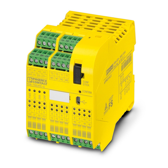
Hardware: PSR-TRISAFE-S safety module Hardware: PSR-TRISAFE-S safety module Device description The PSR-TRISAFE-S safety module is a configurable safety controller with 20 digital safe inputs, which enable the connection of a maximum of 20 single-channel or 10 two-channel safe sensors or control devices. -
Page 34: Block Diagram For The Psr-Trisafe-S Safety Module
I19 M0 M1 M2 M3 POWER 24V DC TEST PULSE MONITORING OUTPUT SAFE INPUT OUTPUT LOGIC CONF SAFE OUTPUT STICK POWER 24V DC 24V 0V O0 O1 O2 O3 O0- O1- Figure 3-2 Block diagram for the PSR-TRISAFE-S safety module PHOENIX CONTACT 103503_en_03... -
Page 35: Operating Modes (Status) Of Psr-Trisafe-S
Hardware: PSR-TRISAFE-S safety module Operating modes (status) of PSR-TRISAFE-S The diagram below illustrates the possible operating modes (status) of the PSR-TRISAFE-S safety module and the possible status transitions. When there is a USB connection to the PC, the module status is indicated on the far left in the status bar of the SAFECONF configuration software. -
Page 36: Operating And Indication Elements
PSR-TRISAFE-S Operating and indication elements All operating and indication elements for the PSR-TRISAFE-S safety module are located on the front of the device. The elements are described in the following sections. IFS-CONFSTICK "Confirm" button Status indicators LEDs - Status of the safe I/Os... - Page 37 Hardware: PSR-TRISAFE-S safety module The LED symbols in the table mean: LED OFF LED ON LED flashing Slowly = 1.7 Hz Fast = 6.3 Hz Table 3-1 Meaning of the status LEDs DATA CONF Meaning (green) (green) (red) (green) Device is switched off, no power supply at...
-
Page 38: Confirm" Button
3.3.2 "Confirm" button Confirming the new The "Confirm" button is on the right-hand side on the front of the PSR-TRISAFE-S safety configuration module, above the USB interface. Press this button using a pen to confirm a new configuration downloaded via the USB interface before it is accepted by the safety module. -
Page 39: Signal Connections
The various signal connections are described in the following sections. 3.4.1 Signal inputs The PSR-TRISAFE-S safety module has 20 digital signal inputs (24 V HTL/3 mA) for the direct connection of safe control devices and/or safety sensors for monitoring and evaluating processes. -
Page 40: Safe Outputs
Cross-circuit detection A "cross circuit" is an unintentional, incorrect connection between redundant circuits. The PSR-TRISAFE-S safety module provides clock outputs T0 and T1 as an aid for detecting such a cross circuit. For example, if two differently clocked signals are routed back to two inputs of the safety... -
Page 41: Alarm Outputs M0 To M3
Hardware: PSR-TRISAFE-S safety module 3.4.3 Alarm outputs M0 to M3 The non-safety-related alarm outputs M0, M1, M2, and M3, are designed as digital semiconductor outputs for 24 V DC/100 mA. These alarm outputs can be used for example to control a standard PLC or a detector unit (e.g., a signal lamp). -
Page 42: Ground Switching Outputs O0- And O1
The ground switching outputs O0- and O1- increase the shutdown protection and cross- circuit protection of the safety system. These outputs can be used for example to switch off a contactor connected to the PSR-TRISAFE-S safety module either via the output or via ground. -
Page 43: Usb Interface
– Forcing signals on the running safety module for startup purposes (standard startup mode) Before the PSR-TRISAFE-S safety module is connected to the configuration PC, the SAFECONF configuration software must be installed with the appropriate USB drivers for the module. -
Page 44: Ifs-Confstick
PSR-TRISAFE-S IFS-CONFSTICK The PSR-TRISAFE-S safety module is equipped with a plug-in memory module, the IFS-CONFSTICK. Figure 3-8 IFS-CONFSTICK on the PSR-TRISAFE-S IFS-CONFSTICK as a The IFS-CONFSTICK must be inserted in the PSR-TRISAFE-S safety module both during hardkey normal operation and for downloading configuration data from SAFECONF via the USB interface. -
Page 45: Installing The Safety Module
3.7.1 Mounting the safety module VORSICHT: Risk of injury and damage to equipment. Only mount and remove the PSR-TRISAFE-S safety module when the power supply is disconnected. For standard extension modules, the PSR-TRISAFE-S safety module is equipped with an interface for the PSR TBUS DIN rail connector on the mounting side (see page 2-3). -
Page 46: Mounting Psr Tbus Din Rail Connectors
PSR-TRISAFE-S To mount the PSR-TRISAFE-S safety module, proceed as follows: Mounting a 35 mm DIN rail The safety module should only be mounted on 35 mm DIN rails according to DIN EN 60715. To avoid contact resistance only use clean and corrosion-free DIN rails. - Page 47 DIN rail. 3.7.1.2 Removal To remove the PSR-TRISAFE-S safety module, proceed as follows: Pull the locking latch on the bottom of the module down using a screwdriver, for example, to release the module from the DIN rail.
-
Page 48: Connecting The Supply Voltage
PSR-TRISAFE-S 3.7.2 Connecting the supply voltage The PSR-TRISAFE-S safety module has no main switch and is switched on simply by applying the supply voltage. The safety logic and alarm outputs are supplied with power via connections A1/A2, the safe outputs, clock outputs, and ground switching outputs are supplied via connections 24V/0V. -
Page 49: Connecting The Signal Lines
Hardware: PSR-TRISAFE-S safety module 3.7.3 Connecting the signal lines VORSICHT: Ensure signal redundancy. Ensure signal redundancy when connecting the signal lines of two-channel control devices and sensors to the inputs of the safety module. Please refer to "Signal inputs" on page 3-7. - Page 50 PSR-TRISAFE-S 3-18 PHOENIX CONTACT 103503_en_03...
-
Page 51: Safeconf Configuration Software
The installation routine for the configuration software also includes the installation of the required driver for the USB interface. This driver is required to enable communication between the PC on which SAFECONF is installed and the PSR-TRISAFE-S safety module. To ensure that the configuration software detects the safety module automatically and correctly, the software must be fully installed on the computer before the device is connected for the first time. - Page 52 PSR-TRISAFE-S Linking I/Os with safety – PSR-TRISAFE-S inputs and outputs are easily linked with the safety logic using drag & logic drop. Parameterizing I/Os – Parameterization of the inputs and outputs of the PSR-TRISAFE-S safety module using a safe parameterization editor.
-
Page 53: Description Of The User Interface
(using drag & drop) and connecting them to one another. Toolbox The toolbox contains the safe functional blocks and safe functions. These elements can easily be dragged from the toolbox to the connection editor. 103503_en_03 PHOENIX CONTACT... - Page 54 PSR-TRISAFE-S Hardware editor The hardware editor contains a graphical representation of the PSR-TRISAFE-S safety module. When configuring the safety logic, input and output signals can be moved from here to the connection editor using drag & drop. Double-clicking on the hardware editor starts the safe device parameterization editor (not shown in the figure).
-
Page 55: Safe Functional Blocks And Functions
SAFECONF configuration software Safe functional blocks and functions The PSR-TRISAFE-S safety module is configured in the SAFECONF configuration software by graphically connecting prepared safe functions and safe functional blocks. Figure 4-2 Safe functional blocks in the toolbox (excerpt) The connections are made intuitively using the mouse, and the editor prevents impermissible connections (e.g., between certain outputs). - Page 56 PSR-TRISAFE-S Table 4-1 Safe functional blocks Name Short description Icon in editor Antivalent The Antivalent safe functional block monitors the signals of two safe input terminal blocks for different signal states. Typically, these signals come from two-channel sensors or switches, such as an emergency stop control device.
- Page 57 A mechanical mode selector switch can be used, for example, to set a specific safety level (e.g., service mode, setup mode, cleaning mode, etc.) for operation of the safe application. 103503_en_03 PHOENIX CONTACT...
- Page 58 PSR-TRISAFE-S Table 4-1 Safe functional blocks (Fortsetzung) Name Short description Icon in editor MutingPar_2Sensor The MutingPar_2Sensor safe functional block evaluates the signals of two muting sensors and one optoelectronic protective device (e.g., light grid) in an application for parallel muting using two sensors and sets the enable signal at output OUT.
- Page 59 A detailed description of each functional block and function is available in the online help. To open the help for a particular safe functional block or safe function, right-click on the corresponding block in the SAFECONF connection editor and select "Help" from the context menu. 103503_en_03 PHOENIX CONTACT...
-
Page 60: Operating The Safeconf Configuration Software
PSR-TRISAFE-S Operating the SAFECONF configuration software Intuitive operation The SAFECONF configuration software follows the Windows standard for all user activities. However, SAFECONF offers a wide range of functions, which far exceeds the standard level of performance in this sector. Examples include online diagnostic tools and simulation of the safety module. -
Page 61: Adding And Connecting Functions, Functional Blocks, And Signals In The Safety Logic
In order to process the various signals (inputs, outputs, and alarm outputs of the PSR-TRISAFE-S safety module) in the connection editor, the signals must be inserted in the connection editor from the hardware editor and connected to other objects. -
Page 62: Figure 4-5 Opening The Hardware Editor With The Auto-Hide Function Enabled
PSR-TRISAFE-S Display the hardware editor ("Hardware Editor" in the "View" menu). If the auto-hide function is enabled, position the cursor over the minimized window as shown in the figure below. Figure 4-5 Opening the hardware editor with the auto-hide function enabled... - Page 63 Clock outputs T0 and T1 of the safety module cannot be moved to the connection editor using drag & drop. To implement cross-circuit detection using these two test pulses, the relevant safety module inputs must instead be parameterized accordingly. 4-13 103503_en_03 PHOENIX CONTACT...
-
Page 64: Figure 4-7 Connecting Objects Using A Line
PSR-TRISAFE-S Connecting objects As shown in Figure 4-6 on page 4-12, signal inputs and outputs as well as constants can be connected as soon as they are inserted in the connection editor (using drag & drop). Free terminal points are connected as described below. -
Page 65: Device Parameterization In The Safe Parameter Editor
To open the device parameterization editor for only one specific I/O, double-click on the relevant signal in the graphical representation of the device: Doppelklick Double click 103503a021.eps Figure 4-10 Opening the device parameterization editor for one specific I/O 4-15 103503_en_03 PHOENIX CONTACT... - Page 66 PSR-TRISAFE-S Instead of double-clicking, you can also open the device parameterization editor via the context menu. Right-click either directly on a specific I/O to open the parameters for this I/O, or on any empty position in the graphical representation of the device to open the general view.
- Page 67 Printing parameters The print dialog box ("Print Project" in the "File" menu) contains a "Safe parameters" checkbox. If this checkbox is selected before printing a project, all the parameters of the safe device are printed too. 4-17 103503_en_03 PHOENIX CONTACT...
-
Page 68: Checking, Downloading, And Starting Up The Project
PSR-TRISAFE-S 4.5.4 Checking, downloading, and starting up the project The project can only be checked if you have logged on with the correct project password ("Log On" in the "Project" menu). If the current project status has not yet been saved, this is done automatically prior to checking. -
Page 69: Documenting The Signal Assignment And The Project
To ensure compliance with standards, the fields with yellow row headers must be completed each time a new project version is developed. The fields with a gray background are less important. However, it is highly recommended that you enter data in all fields. 4-19 103503_en_03 PHOENIX CONTACT... - Page 70 PSR-TRISAFE-S Check values (CRC): If the project documentation is modified, the check value is recalculated, i.e., the system detects that the project on the safety module differs from the configuration project. If the check values on the safety module and in the configuration software are not identical, a corresponding message is output.
-
Page 71: Simulation Mode In Safeconf
The SAFECONF configuration software includes the EASYSIM controller simulation, which can be used to simulate the execution of the safety logic: – If no PSR-TRISAFE-S safety module is available – If a simulated function test is recommended prior to actual startup of the "real"... - Page 72 PSR-TRISAFE-S Starting simulation mode To start the simulation and download a project, proceed as follows: To start the simulation, click on the "Simulate Safety Controller" icon in the toolbar. If the icon is activated, the simulation is active and all commands executed, such as "Download"...
- Page 73 Once the "Simulate Safety Controller" icon is selected again, the destination system is reset in the configuration software, from the EASYSIM simulation to the real PSR-TRISAFE-S safety module. This means that, essentially, the connection between the configuration software and the simulation software is only interrupted. The EASYSIM simulation application is not exited automatically (see below).
- Page 74 PSR-TRISAFE-S 4-24 PHOENIX CONTACT 103503_en_03...
-
Page 75: Configuration And Startup
Configuration overview from A to Z The diagram below describes the simplified sequence, i.e., the general procedure, for developing a configuration project and for starting up the PSR-TRISAFE-S safety module. For detailed information, please refer to the specified sections and the SAFECONF online help. -
Page 76: Figure 5-2 Flowchart: Configuration From A To Z (2 Of 3)
Continued (B) ..Continued (from A) Switch on the PSR-TRISAFE-S (apply supply voltage, see page 3-16) and connect to the USB interface of the PC (see page 3-11). Alternative: Instead of using the safety module, check the function of the safety logic using the EASYSIM simulation. -
Page 77: Figure 5-3 Flowchart: Configuration From A To Z (3 Of 3)
Documentation in SAFECONF Complete the project information: "Project" menu, "Project Information" Archive the project in SAFECONF (zip and save to backup medium) Print the project in SAFECONF Figure 5-3 Flowchart: Configuration from A to Z (3 of 3) 103503_en_03 PHOENIX CONTACT... -
Page 78: Downloading The Configuration From Safeconf
The configuration, including the device parameterization, is created in the SAFECONF configuration software as a project and must be downloaded to the PSR-TRISAFE-S safety module once complete. This data is usually transmitted via the USB interface of the safety module. -
Page 79: Figure 5-4 Usb Connection Between Pc And Safety Module
Figure 5-4 USB connection between PC and safety module The project can only be downloaded to the PSR-TRISAFE-S safety module if you have logged on in SAFECONF with the correct controller password. In the "Safe Controller" menu, select "Log On", enter the controller password in the dialog box and click "OK". -
Page 80: Figure 5-5 Message Dialog Box Following Successful Data Transmission
PSR-TRISAFE-S Do not confirm this message yet, first complete the following step. Please note: First acknowledge the configuration on the safety module (see step 6.) ..before clicking "OK". Figure 5-5 Message dialog box following successful data transmission Confirm the new configuration by pressing the "Confirm" button using a pen (see Figure 5-6). -
Page 81: Downloading The Configuration Using The Ifs-Confstick
The safety module now detects the previously unknown IFS-CONFSTICK and indicates this by making the "CONF" status LED flash. Remove the IFS-CONFSTICK again. Press the "Confirm" button on the device and hold it down. 103503_en_03 PHOENIX CONTACT... -
Page 82: Figure 5-7: Pressing The "Confirm" Button While Inserting The
PSR-TRISAFE-S Reinsert the IFS-CONFSTICK while holding down the "Confirm" button. Hold down the "Confirm" button while inserting the IFS-CONFSTICK Figure 5-7 Pressing the "Confirm" button while inserting the IFS-CONFSTICK Release the "Confirm" button once the IFS-CONFSTICK is inserted correctly. The safety module now initializes with the new configuration. -
Page 83: Uploading The Configuration From The Psr-Trisafe-S Safety Module
Uploading the configuration from the PSR-TRISAFE-S safety module A project which is downloaded to the PSR-TRISAFE-S safety module is saved there and can be uploaded to the PC and the configuration software again if required. This may be required, for example, if a project has to be read from the safety module for diagnostic purposes. -
Page 84: Function Test
Function test Validation Once the project has been loaded onto the PSR-TRISAFE-S safety module and executed from this point (following manual confirmation), you must perform a function test to ensure that the safety module is working correctly and, therefore, that the safety logic and all the cabling are working correctly as well. -
Page 85: Startup Mode
The test of the safety application using startup mode must not replace the proper function test using safe control devices. The test in startup mode may only be performed in addition to the standard function test, as a preliminary test, for example. 5-11 103503_en_03 PHOENIX CONTACT... - Page 86 PSR-TRISAFE-S Forcing signals in the online display of the connection editor directly controls the safety module. WARNING: Eliminate hazards Before forcing any signals, ensure that doing so will not pose a risk for people or materials. WARNING: Startup mode is a standard operating mode As in online mode, the connection editor displays online values, which are read from the safety module.
- Page 87 A confirmation dialog box appears, where "Yes" should be clicked to exit startup mode. The yellow background of the status field on the right-hand side of the status bar indicates that the safety module is running in safe normal operation again. 5-13 103503_en_03 PHOENIX CONTACT...
- Page 88 PSR-TRISAFE-S 5-14 PHOENIX CONTACT 103503_en_03...
-
Page 89: Application Examples
SAFECONF as well as the wiring of the PSR-TRISAFE-S safety module in the form of schematic views. The online help also includes typical signal sequence diagrams, which illustrate the behavior of each functional block. - Page 90 PSR-TRISAFE-S PHOENIX CONTACT 103503_en_03...
-
Page 91: Problems And Solutions
This section provides a list of possible problems, which may occur when working with the SAFECONF configuration software and the PSR-TRISAFE-S safety module. The action to be taken and the way in which the user must respond in order to solve the issue is described for each individual problem. -
Page 92: Graphical Connection Editor
PSR-TRISAFE-S Graphical connection editor Table 7-2 Solutions for problems with the graphical connection editor Problem Solution You have attempted to open a project, but The project concerned is damaged and can the safety logic could not be loaded due to no longer be used. -
Page 93: Online Communication Between Safeconf And The Psr-Trisafe-S Safety Module
Problems and solutions Online communication between SAFECONF and the PSR-TRISAFE-S safety module Table 7-4 Solutions for communication problems Problem Solution A connection cannot be Proceed as follows: established to the safety Remove the USB connecting cable from the PC and safety module. - Page 94 PSR-TRISAFE-S Table 7-4 Solutions for communication problems Problem Solution Transmission has been Start transmission again. interrupted during the download If the download procedure fails once more, remove procedure. the USB connecting cable from the interface on the configuration computer and reinsert it.
-
Page 95: Safety Module Messages
Problems and solutions Safety module messages Table 7-5 Solutions for PSR-TRISAFE-S safety module messages Problem Solution Following acknowledgment of the newly 1. Switch the safety module off and on loaded configuration, the safety module is again. not initialized correctly ("Controller: Error" in 2. - Page 96 PSR-TRISAFE-S PHOENIX CONTACT 103503_en_03...
-
Page 97: List Of Figures
Figure 1-1: Calling the online help in the SAFECONF configuration software ..1-8 Section 2 Figure 2-1: Typical structure of a safety system with PSR-TRISAFE-S ....2-1 Figure 2-2: PSR TBUS DIN rail connector from Phoenix Contact ......2-3 Figure 2-3: Implementing a startup inhibit, restart inhibit, and stop category 0 for safe output O0 ................ - Page 98 PSR-TRISAFE-S Section 4 Figure 4-1: SAFECONF user interface ..............4-3 Figure 4-2: Safe functional blocks in the toolbox (excerpt) ........4-5 Figure 4-3: Project Wizard for creating a new configuration project, using a project template ..............4-10 Figure 4-4: Inserting safe functional blocks and functions from the toolbox in the connection editor ..............
-
Page 99: Index
Configuration project, see Project Connecting objects in the connection editor..... 4-14 Connection editor 2-2, 2-11, 3-7, 4-3, 4-11, 5-1, 5-10, 7-2 Connections on the PSR-TRISAFE-S ......3-7 Ground switching outputs O0-, O1-..3-1, 3-10, 4-17 Controller password, see Password protection GuardLocking (safe functional block).... - Page 100 Machinery Directive 2006/42/EC......1-5, 2-4 Diagnostic tools............ 2-9 Machinery Directive 98/38/EC........1-5 Downloading the configuration using the IFS- Method of operation of the PSR-TRISAFE-S system . 2-1 CONFSTICK ............5-7 MINI-SYS-PS system power supply unit ....3-16 Ground switching outputs O0-, O1- ....3-10 MINI-SYS-PS, system power supply unit ....
- Page 101 Test pulses T0, T1 ..... 2-8, 3-1, 3-8, 3-9, 4-13, 4-16 Safety concept ............1-4 TestableSafetySensor (safe functional block) ..2-6, 4-9 Safety integrity ............ 1-4, 1-7 Time limit when changing operating mode....5-12 Toolbox ............. 4-3, 4-11 103503_en_03 PHOENIX CONTACT...
- Page 102 TwoHandControlTypeII (safe functional block) ..4-9 TwoHandControlTypeIII (safe functional block) ..4-9 Uploading the configuration from the PSR-TRISAFE-S..Uploading the project from the PSR-TRISAFE-S ..5-9 USB interface........2-2, 3-11, 5-4, 5-7 Use, intended............1-7, 3-9 Wiring check ............2-11 Wiring documentation ..........
Need help?
Do you have a question about the PSR-TRISAFE-S and is the answer not in the manual?
Questions and answers
Error chiqip qolgan 8shlamayapti