
Summary of Contents for Actisense EMU-1 Series
- Page 1 EMU-1 Engine Monitoring Unit Analogue to NMEA 2000 ® User Manual For variant: EMU-1-BAS Issue 1.06...
-
Page 2: Table Of Contents
NMEA 2000 Engine Monitoring Unit - EMU-1 Contents Company information Important Notices Trademarks and Registered Trademarks Fair use Statement Technical Accuracy Product Registration Product Guarantee Product Disposal Product Overview Figure 1 - Example of an EMU-1 Installation Package Contents Installation Warnings Installation Order Selecting a Mounting Location Figure 2 - Example of a Typical Installation... -
Page 3: Company Information
EMU-1. Alternatively, if your EMU-1 is inaccessible, you will find the serial number under the product information on the ‘network list’ page of an NMEA 2000 MFD. Your registration will assist Actisense Support to link your product to your details, simplifying any future assistance you may require. -
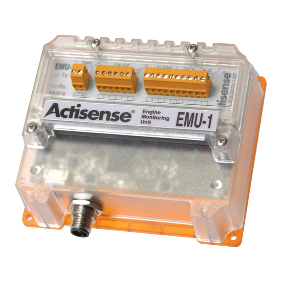
Page 4: Product Overview
The EMU-1 provides 6 dedicated Gauge inputs, capable of measuring the output from the required engine senders. The The Actisense EMU-1 is designed to reliably measure voltage levels on senders and sensors; the accuracy is reliant unit also provides 4 Alarm inputs (e.g. high temp, low pressure), 2 Tacho inputs, and 2 user definable Auxiliary inputs. -
Page 5: Installation Order
NMEA 2000 Engine Monitoring Unit - EMU-1 Installation Order Wiring Loom Lengths 1. Select mounting location: Ensure the EMU-1 can be mounted in a suitable location relative to the NMEA 2000 bus Installations without Gauges Installations with Gauges and the senders or gauges. See “Selecting a Mounting Location”... -
Page 6: Mounting The Emu-1
NMEA 2000 devices will only communicate with each other when connected to a powered and correctly • An Actisense DIN Rail Kit (not included with the EMU-1) Part Code: DIN-KIT-1 All NMEA 2000 networks require a 12V DC supply. terminated NMEA 2000 network. It is not enough to simply •... -
Page 7: Gauge Input Connections
NMEA 2000 Engine Monitoring Unit - EMU-1 Gauge Input Connections Alarm Input Connections There are six Gauge inputs which are designed to be connected to existing engine senders (resistive type) either with There are four Alarm inputs which are designed to be connected to existing alarm type switches. The EMU-1 can be or without the gauge connected. -
Page 8: Tacho Input Connections
NMEA 2000 Engine Monitoring Unit - EMU-1 Tacho Input Connections Calculating Tacho PPR Figure 9 - Tacho Input Connections The EMU-1 configuration tool allows the “ratio” to be configured. This ratio is usually referred to as the PPR (Pulses Per Revolution). - Page 9 The LED flashes orange on transmission of an NMEA 2000 PGN message. • An NGT-1 (either the ISO or USB variant). • A PC running the Actisense EMU-1 Configuration Tool. The tool is provided on the CD but it is recommended that the Technical Support and the Returns Procedure latest version is downloaded from www.actisense.com/EMU-1/Downloads.
- Page 10 NMEA 2000 Engine Monitoring Unit - EMU-1 Supported NMEA 2000 PGNs Specifications Table 4 - Specification Table Table 3 - NMEA 2000 PGN List Power Supply Tacho Inputs PGN Name Data Tx Rate Voltage Range ±3 to ±60V Supply Voltage 9 to 35V DC 59392 ISO Acknowledge...
- Page 11 (EN 50 035) rails STNG-A06045 SeaTalkNG to NMEA 2000 adaptor cable (drop). Active Research Ltd Unit 5, Wessex Trade Centre Ringwood Road Poole, Dorset UK, BH12 3PF Telephone: +44 (0)1202 746682 Email: sales@actisense.com www.actisense.com Web: ® © 2015 Active Research Limited Page 20...
Need help?
Do you have a question about the EMU-1 Series and is the answer not in the manual?
Questions and answers