
Related Manuals for Euromag MC608 Series


Summary of Contents for Euromag MC608 Series
- Page 1 MC608 Converter I n s t a l l a t i o n M a n u a l Ve r s . 6 . 0 a n d s u b s e q u e n t PLEASE READ THESE INSTRUCTIONS AND KEEP IN A SAFE PLACE TD 210-1-ENG...
- Page 3 For applications that require high working pressures or substances that may be hazardous to the people, the environment, equipment or anything else if a pipe breakage occurs, Euromag International recommends, that before installing the sensor the operator takes the appropriate precautions such as precautions such as the correct location, protection or the mounting of a guard or safety valve.
- Page 4 CAUTION! RISK OF ELECTRIC SHOCK! ALL OPERATIONS MARKED WITH THIS SYMBOL SHOULD ONLY BE CARRIED OUT BY QUALIFIED TECHNICIANS. CAUTION! CRUCIAL INFORMATION AND INSTRUCTIONS TO BE APPLIED. PLEASE REFER TO THE ANNEXED DOCUMENTS . NOTE INFORMATION AND INSTRUCTION REQUIRING SPECIAL ATTENTION. CE/EMC/Norme The manual that describes this flowmeter conforms to the following safety rules: •...
-
Page 5: Manufacturer's Design And Safety Statement
38.3” for transport by air and with the provisions of the ADR regulations for the transport by truck/sea. • Remove the battery from the transmitter before returning the flow meter to Euromag International for possible service or warranty claim. -
Page 6: Table Of Contents
3.3.7 INSTALLATION EXAMPLE OF WAFER METER (MUT1000EL – MUT1100J) 21 4. POTENTIAL EQUALIZATION 5. NEGATIVE PRESSURE IN THE PIPE 6. INSTRUCTIONS FOR DIAMETER REDUCTION 7. INFORMATION CONCERNING THE MC608R CONVERTER 8. INSERTION METERS 8.1 INTRODUCTION 8.1.1 FEATURES AND BENEFITS EUROMAG | MC608 | TD210-1... - Page 7 8.1.2 SYSTEM DIAGRAM 8.1.3 MECHANICAL INSTALLATION 8.2 INSTALLATION 8.2.1 MEAN AXIAL VELOCITY POINT (1/8 OF THE INTERNAL DIAMETER) 8.2.2 ALIGNMENT 8.2.3 PROGRAMMING 9. MC 608 CONVERTER 9.1 INSTALLATION 9.1.1 IDENTIFICATION NAMEPLATE 9.1.2 COMPACT VERSION 9.1.3 REMOTE VERSION 9.1.4 ELECTRICAL CONNECTIONS 9.1.5 MODBUS RS485 OUTPUT 9.1.6 ELECTRICAL GROUNDING OF THE COVERTER CASE 9.1.7 CONNECTION TO THE POWER SUPPLY...
- Page 8 10.4.1 PULSE OUTPUT 10.4.2 FREQUENCY OUTPUT 10.4.3 PROGRAMMABLE OUTPUT 10.4.4 PROGRAMMABLE INPUT 10.4.5 BATCHING 10.4.6 PROGRAMMABLE OUT LOGIC 10.5 OTHERS 10.5.1 SYSTEM INFO 10.5.2 TIME/DATE 10.5.3 RESERVED 10.5.4 GRAPH 10.5.5 SIMULATION 10.5.6 COMMUNICATIONS 10.5.7 DATA CONNECTION (RS485/IRCOMM) EUROMAG | MC608 | TD210-1...
- Page 9 10.6 MEMORY 10.6.1 LOAD USER COPY 10.6.2 SAVE USER COPY 10.6.3 FACTORY SETTINGS 10.6.4 DATALOGGER 10.6.5 PASSWORD SETUP 11. TECHNICAL DATA 11.1 GENERAL FEATURES 11.2 CERTIFICATES AND APPROVALS 11.4 ACCURACY 12. RETURN OF THE FLOW METER FOR ANY CHEK OR REPAIR 13.
-
Page 10: Preliminary Notes
The proper lifting method is shown in Figure fig_2_1, while it must be avoided that shown in Figure fig_2_2; to be noticed, do NOT raise the flow meter gripping the converter, but always holding it on the sides. fig_2_1 fig_2_2 EUROMAG | MC608 | TD210-1... - Page 11 Moreover: DO NOT move the flow meter with the lifting device without the original packaging or without the help of an appropriate support, ensuring the required stability. Separate version fig_2_3 Compact version fig_2_5 IP67 Electronics (Nema 4x) IP68 Sensor (Nema 4x) •...
-
Page 12: Sensor Installation
• in the opposite direction to that indicated by the arrow (enter by + and exit by –), the flow is negative and the display will show a reading with negative sign; FLOW negative figure-> reverse flow direct flow -> figure without sign EUROMAG | MC608 | TD210-1... -
Page 13: Installation Instructions
INSTALLATION INSTRUCTIONS IMPORTANT NOTE THE SENSOR MUST ALWAYS BE COMPLETELY FULL WITH LIQUID! 3.3.1 POSITIONING IN RELATION TO THE PLANT For efficient working conditions, please carefully follow the instructions in figure 3_3_1. The flow meter must remain below the hypothetical blue line (piezometric level line) which connects the two levels of fluid to be measured. -
Page 14: Positioning In Relation To The Flow
Recommended installation is on a vertical/inclined pipe with upward flow direction, to minimize the wear and deposits in the sensor. Avoid installation in vertical pipes with free outlet. Installation NOT enabling the empty pipe detection fig_332_2 fig_332_5 EUROMAG | MC608 | TD210-1... -
Page 15: Important Instructions On Mounting
3.3.3 IMPORTANT INSTRUCTIONS ON 3.3.4 CHARTS OF MAXIMUM MOUNTING ALLOWABLE TIGHTENING TORQUES Use elastic pipe fittings where there is not adequate Standard bolts must be well lubricated and tightened distance between the sensor and the pipe. Do not evenly around the gasket. If the bolts are tightened attempt to bring the pipe to the sensor by tightening excessively, they may result in leaks or damage to the bolts. - Page 16 150/300 ≤10 ≤145 2 1/2” 2 1/2” 150/300 ≤10 ≤145 3” 3” 150/300 ≤10 ≤145 4” 4” 150/300 ≤10 ≤145 5” 5” 150/300 ≤10 ≤145 6” 6” 150/300 ≤10 ≤145 8” 8” 150/300 ≤10 ≤145 EUROMAG | MC608 | TD210-1...
-
Page 17: Important Guidelines For Correct Installation
3.3.5 IMPORTANT GUIDELINES FOR CORRECT INSTALLATION For a correct working condition please follow the important guidelines shown in the following figures. Improper installation result in inaccurate measurement. To achieve the most accurate flow measurement it is essential to have minimum straight lengths of the inlet and outlet pipes as shown (DN: sensor nominal diameter) •... - Page 18 • The position on the left is correct, the other two ARE NOT. fig_335_6 fig_335_4 • DO NOT place the sensor close to any variation in the path of the flow. • This installation DOES NOT guarantee a full pipe condition. fig_335_7 fig_335_5 EUROMAG | MC608 | TD210-1...
- Page 19 • DO NOT place any gate valve directly connected upstream the sensor. fig_335_10 fig_335_8 • DO NOT use the sensor as a support for the tube. • Always install the sensor downstream the pump and NEVER upstream to avoid vacuum. fig_335_11 •...
-
Page 20: Important General Information For A Proper Installation
AVOID ANY EXCESSIVE VIBRATIONS Protective cover fig_336_2 • AVOID exposing the flow meter to strong or Fill with an nearby magnetic fields. adequate amount of material fig_335_15 fig_336_3 EUROMAG | MC608 | TD210-1... -
Page 21: Installation Example Of Wafer Meter (Mut1000El - Mut1100J)
• Protect the flow meter if exposed to direct sun IMPORTANT NOTE radiations. NOTE FOR CONNECTION OF ATEX APPROVED FLOW METERS CABLING REQUIREMENTS IN POTENTIALLY EXPLOSIVE ATMOSPHERES (ATEX). LAY THE CABLES AS REQUIRED BY STANDARD EN 60079-14, IN PARTICULAR PROVIDING MECHANICAL PROTECTION, FOR EXAMPLE, RIGID OR FLEXIBLE CONDUIT PIPES, DUCTS OR SIMPLY CRANKCASES. -
Page 22: Potential Equalization
This ensures that Grounding rings are not supplied as standard. any noise is transported through the body of the sensor thereby achieving a measurement area free from noise within the body of the sensor EUROMAG | MC608 | TD210-1... - Page 23 Metal pipe with adapters PLASTIC PIPE PLASTIC PIPE METAL PIPE METAL PIPE fig_4_5 GROUNDING RINGS Metal and plastic pipe METAL PIPE PLASTIC PIPE GROUNDING RING fig_4_3 NOTE fig_4_6 GROUNDING CABLE: • Particularly close attention must be paid when MIN 2.5 MM2 RECOMMENDED: 4 MM2 installing the product in the pipeline with GROUNDING SCREW: 5MM...
-
Page 24: Negative Pressure In The Pipe
In the event of a reduction in the diameter, refer to the instructions given in the figure below. UNI EN ISO 6817:1997 REFERENCES 1 VENT 2 POINT ANGLE LIMIT: 15º 3 FLOW METER 4 FLOW 5 BLEEDING 5 D MIN. fig_6_1 EUROMAG | MC608 | TD210-1... -
Page 25: Information Concerning The Mc608R Converter
7. INFORMATION CONCERNING THE MC608R CONVERTER Position Screw Pivot Screw Axial point fig_7_1 • Connect the battery pack (blue cables). • Insert the cartridge into the extension cylinder. • Mount the aluminium rear box, and screw on in order to obtain an optimal sealing through the O-ring. -
Page 26: Insertion Meters
- All data can be downloaded through the GE TO THE PROBE MAY COM- software MC608, made available as standard. PROMISE THE FLOWMETER AND ITS PERFORMANCES • ANY PHYSICAL DAMAGE TO THE PROBE OF THE FLOWME- TER INVALIDATES THE WAR- RANTY EUROMAG | MC608 | TD210-1... -
Page 27: System Diagram
8.1.2 SYSTEM DIAGRAM - Within environmental limits 10 m Pressure (30 ft) gauge IP68 (NEMA 6) fig_813_2 - Avoid excessive vibration fig_812 8.1.3 MECHANICAL INSTALLATION AVOID • Localization - installation and environmental EXCESSIVE conditions. VIBRATION - Within the temperature limits fig_813_4 Temperature of the liquid: •... -
Page 28: Installation
ARROW ON THE HANDLES, IN THE DIRECTION CORRESPONDING TO THE FLOW. Orientation 10DN 15DN fig_813_5 in line with the centre fig_813_7 NOTE THE PIPE MUST BE ALWAYS FULL 8.2 INSTALLATION • Localization - Mechanics - Overall dimensions 25 mm (1”) Minimum distance fig_821_1 fig_813_6.tif EUROMAG | MC608 | TD210-1... -
Page 29: Mean Axial Velocity Point (1/8 Of The Internal Diameter)
(see section 10.3.2 Diameter setup). H: Body constant size (140mm) I: insertion depth (Dint / 8) M: Check for the measurement of insertion ES: Euromag original parts standard size (225mm) L: total size of the device (400mm) M = Ltot.-ES-S-(Dint/8) M = 175-S-Dint./8 Example: D = 200mm, S = 3mm 8. -
Page 30: Mc 608 Converter
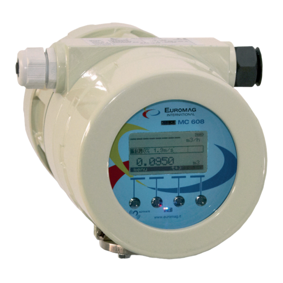
• COUPLING: serial number identifying the sensor coupled to the converter • OPTIONAL: other modules may be added fig_9_1 9.1.2 COMPACT VERSION Figure 55 represents the converter MC 608 in the compact layout. • MC 608A • MC 608B EUROMAG | MC608 | TD210-1... -
Page 31: Remote Version
9.1.3 REMOTE VERSION When the converter is purchased in compact version all the electrical connections are already performed by the manufacturer. CAUTION! Before running the converter, proceed connecting the required outputs For safety reasons, the power supply must be wired only after connecting the ONLY SKILLED TECHNICAL STAFF outputs. - Page 32 NOTE THE USE OF CABLES NOT PROVIDED OR CERTIFIED BY EUROMAG INTERNATIONAL MAY AFFECT THE CORRECT WORKING CONDITIONS OF THE SYSTEM AND CAUSE THE WARRANTY VOIDANCE. CAUTION! ALL THE OPERATIONS ON ELECTRICAL CONNECTIONS MAY BE MADE ONLY WHEN THE POWER SUPPLY IS CUT AND THE JUNCTION BOX OF THE CONVERTER IS CAREFULLY CLOSED.
- Page 33 Separate version • MC 608A • MC 608B 9. CONVERTER MC 608...
-
Page 34: Electrical Connections
COMPONENTS OF THE DEVICE MUST BE CARRIED OUT BY PROPERLY TRAINED AND SPECIALIZED STAFF MC608 ELECTRICAL DIAGRAM FREQ OUT GROUND PROG IN RS485 SENSOR COIL SIGNAL HARDWARE VERSION PROG PULSE 24VDC OUT MAX 30mA 4-20mA RESET 12-24Vac/dc USB CABLE CONNECTION fig_914_1 EUROMAG | MC608 | TD210-1... - Page 35 PULSE OUTPUT Active 5-30V (MC608A/B/R) Clean contact (MC608A/B/R) The device connected (PLC/external pulse meter) is a passive digital input that accepts the voltage The device connected (PLC/external pulse meter) supplied to it by the external supply system used. supplies its digital input with the required voltage to detect the pulses.
- Page 36 MC608 24Vdc power accept the voltage level provided by the external supply is internally connected. power supply. (24VDC loop voltage of 24Vdc, maximum (Voltage 5-30V, maximum current 50mA) impedance 800 ohm) MC608 MC608 SOURCE fig_914_7 fig_914_9 EUROMAG | MC608 | TD210-1...
-
Page 37: Modbus Rs485 Output
Active (MC608 version 6.3 and MC608 subsequent) The connected 4-20mA receiver is a passive milliamp-meter; the internal MC608 24Vdc power supply must be connected as shown. SOURCE (24VDC loop voltage of 24Vdc, maximum impedance 800 ohm) fig_914_10 NOTE CONNECT ONLY ONE OUTPUT AT A TIME WITH INTERNAL POWER SUPPLY (7-8) AUX MAX 30 MA 9.1.6 ELECTRICAL GROUNDING OF THE 9.1.5 RS485 MODBUS Output... -
Page 38: Connection To The Power Supply
Euromag software configuration program The unit may be supplied with voltage: MC608 MC608A The Euromag MC608 software can be downloaded via www.euromag.com visiting the download area, 90 … 264 Vac or it can be ordered on CD. O 12 … 24 Vac/dc... - Page 39 MC608 configuration is made via PC using the Euromag MC608 software program. fig_92_3 - Use an USB adapter for direct communication to IrCOM cable PC (available at the manufacturer on request) or an infra-red interface unit. MC608B or MC608R:...
- Page 40 NORMALLY IT IS THE COM WITH THE HIGHEST NUMBER. Select infra-red or 485 or IIrCOM communication for the main page of the software (view f.58). NOTE THE IRDA COMMUNICATION IS AVAILABLE ONLY ON MC608_5 AND MC608_6_1 CONVERTERS. fig_92_5 fig_92_6 EUROMAG | MC608 | TD210-1...
-
Page 41: Programming
CONVERTER PASSWORDS: The converter was built with three different levels of protection. Passwords can be modified. I level: 608111 II level: 709222 III level: 231042 To change passwords see the menu “memory” - password setup. MC608 with correct connection: Parameters can now be read and changed. fig_92_7 9.2.1 PROGRAMMING To access the menu from the converter, simply press on the relevant button below the function. - Page 42 PARAMETERS Program. input Ka setup • Enabled/disabled Diameter Setup • Zeroing p+ Filters setup • Zeroing p- • Flow cut off • Zeroing p+/p- • Damping Batching • Bypass Progr. output logics • Peak cut EUROMAG | MC608 | TD210-1...
- Page 43 ALL PROGRAMMING CAN BE DONE EITHER ON THE CONVERTER menu t+> THROUGH THE PUSH BUTTONS, OR USING THE EUROMAG MC608 SOFTWARE PROGRAM DATA TO BE DISPLAYED The display is divided into 3 main areas. Keypad for programming The top area shows the symbols for status...
-
Page 44: Description Of The Menu
Select the time base for the instant flow rate Data connection in progress • Counters unit Select the volume technical unit for the counters • Pulses unit Select the volume unit for the pulses • Specific weight EUROMAG | MC608 | TD210-1... -
Page 45: Measurement Frequency
10.1.3 DISPLAY You can enter the specific gweight of the liquid used • LCD backlight level • Temperature Unit Increase or decrease backlit level Change the desired temperature unit CAUTION! 10.1.2 MEASUREMENT FREQUENCY • Measuring time Select the measurement time of the system ANY INCREASE OF THIS FACTOR WILL between 10/15/30/45/60/120/180/240/300/360/4 AFFECT BATTERY LIFE WHEN USING... -
Page 46: View Options
External temperature or system operating pressure ft3, cubic feet 28,31685 m with optional add-on modules(s) and sensors bbl oil, oil barrel 158,984 m 0,001 Kg 0,1 Kg 1 Kg 100 Kg 1000 Kg lb, pounds 0,45359 Kg EUROMAG | MC608 | TD210-1... -
Page 47: Parameters
fig_10_2 10.3 PARAMETERS 10.3.1 KA CHANGE It allows to modify the KA calibration factor. Ka setup Diameter Setup CAUTION! Filters setup • Flow cut off • Damping ONLY AUTHORIZED PERSONS CAN MODIFY THE KA FACTOR. THE KA • Bypass FACTOR MUST BE EQUAL TO THE •... -
Page 48: Filters Setup
To increase the stability, increase the value in this sub menu. • Bypass A percentage value that represents a threshold on which the digital filter is NOT calculated. For example: EUROMAG | MC608 | TD210-1... - Page 49 fig_1033_1 10. MENU DESCRIPTION...
-
Page 50: Zero Finder
• Min flow th. Set the minimum value of flow rate in percentage the full scale value. This value is factory disabled. Selectable range goes from 1% to maximum threshold of 95% of the full scale value. EUROMAG | MC608 | TD210-1... -
Page 51: I/O
10.4 I/O 10.4.1 PULSE OUTPUT • Pulse quantity Pulses OUT Select the volume of the pulses. • Pulse quantity • Pulses time ON CAUTION! • Reverse flow rate • Pulse output enable Frequency output WITH MC608B OR MC608R SELECT A VOLUME LARGE ENOUGH SO THAT •... -
Page 52: Frequency Output
Acting on this function, in the case of negative flow, the pulses from the pulse output will be enable/ disabled • Enable pulse output Select to disable the frequency output and activate the pulse output (factory condition) EUROMAG | MC608 | TD210-1... -
Page 53: Programmable Input
10.4.4 PROGRAMMABLE INPUT 10.4.5 BATCHING You can choose between one of the following Set the volume to be dosed. Available only with options for the programmable input: MC608A • Enabled/disabled Example of connection to the programmable output • Zeroing p+ •... -
Page 54: Programmable Out Logic
Menu -> Other -> Communication -> Data 10.5.3 RESERVED Connection -> IrCOMM Menu under exclusive use of the manufacturer. 10.5.4 GRAPH Shows the graph of the measured flow rate 10.5.5 SIMULATION The MC608 has a built in flow simulator EUROMAG | MC608 | TD210-1... -
Page 55: Memory
10.6 MEMORY WITH BATTERY POWERED MC608B MC608R PRIORITY IS GIVEN BY THE RANGE OF Load user copy MEASUREMENT. Save user copy (ACQUISITION> = MEASUREMENT) Factory settings To read and change the memory data from the Datalogger MC608 software program, move to the DATA LOG screen - see the picture below. - Page 56 After reading the data, moving to the GRAPH screen will also be available a flow rate chart, see the figure below. To change the storage time of the data logger, click read, and then act on the horizontal scroll key between EUROMAG | MC608 | TD210-1...
-
Page 57: Password Setup
fig_1064_2 10.6.5 PASSWORD SETTING Allows you to change the 3 levels of password. To access the selection of the 3 pwd to be changed (L1, L2, L3) the level 3 password is prompted. 10. MENU DESCRIPTION... -
Page 58: Technical Data
Storage: -30 C° to 70 C° Signal cables Euromag cables: • CA22 - cables for sensors with 4 electrodes • CA23 - cables for 2 or 3 electrode sensors Consumption MC608A: • Min 5W • Max 10W EUROMAG | MC608 | TD210-1... -
Page 59: Certificates And Approvals
Pressure sensor PA21Y: 0...20 Bar; 1/8” GAS male, connector with fly coupling installed in factory; standard cable 5m long; code PRTR00001 Temperature PT500: CLASS A, 4-wire,-20C° to 180°C; 1/4” cockpit included, 50mm long, sensor 6mm diameter; standard cable length 5m; code PRTR00002 11.2 Certificates and approvals This device fulfils the legal requirements of the EC directives. -
Page 60: Accuracy
0,60 0,40 0,20 0,00 -0,20 -0,40 -0,60 -0,80 -1,00 -1,20 10,0 Velocità [m/s] Graph 1 CLASS 05 3,00 2,50 2,00 1,50 1,00 0,50 0,00 -0,50 -1,00 -1,50 -2,00 -2,50 -3,00 10,0 Velocita [m/s] Graph 2 EUROMAG | MC608 | TD210-1... -
Page 61: Return Of The Flow Meter For Any Chek Or Repair
CLASS 2 2 4,00 3,50 3,00 2,50 2,00 1,50 1,00 0,50 0,00 -0,50 -1,00 -1,50 -2,00 -2,50 -3,00 -3,50 -4,00 10,0 Velocità [m/s] Graph 3 12. RETURNING A FLOWMETER FOR CHECK UP AND REPAIR The device was carefully manufactured and has passed rigorous testing before leaving the factory. If correctly installed and maintained, the event of a malfunction should be highly unlikely. -
Page 62: Appendix - Troubleshooting
• Increase the bypass filter External pulse totalizer Test the output with the external flow simulator and the converter-pulse shows results different counter system, simulating a flow rate through System > Simulation. from the expected ones. EUROMAG | MC608 | TD210-1... - Page 63 The display is off and There is no voltage supply, or the voltage supply is incorrect. Check the does not turn on. power supply voltage on the name plate of the converter. In case of MC608B check the battery life and replace the battery pack. Liquid is flowing and Reduce the flow cut off filter (factory settings is 2% of the full scale) the pipe is filled, but NO...
- Page 64 • Supply voltage out of operating range • Converter damaged Check the power supply network Data logger full • Data logger memory full It is advisable to download the data to PC, and erase the memory of the converter EUROMAG | MC608 | TD210-1...
-
Page 65: Repair Application Form
REPAIR APPLICATION FORM Company Name _____________________________________________________________ Company address ____________________________________________________________ _____________________________________________________________________________ Phone _____________________________________ Fax. ___________________________ Type of sensor / converter ____________________ Series No. _____________________ Type of liquid _______________________________ Interior cleaning (Y / N) ___________ Claim _______________________________________________________________________ _____________________________________________________________________________ _____________________________________________________________________________ _____________________________________________________________________________ We hereby confirm that there is no risk to persons or the environment due to any residual substances contained in the device that is returned Data _______________________________________ Company stamp ____________________________ Signature _______________________... -
Page 66: Note
Note EUROMAG | MC608 | TD210-1... - Page 67 NOTE...
- Page 68 Euromag International SRL Via Torino 3-35035 - Mestrino - PADOVA - ITALY Tel. +39/049.9005064 - Fax. +39/049.9007764 euromag@euromag.com - www.euromag.com TD 210-1-ITA...
Need help?
Do you have a question about the MC608 Series and is the answer not in the manual?
Questions and answers