
Related Manuals for Telex Airman 8


Summary of Contents for Telex Airman 8
- Page 1 Airman 8 Headset Maintenance & Overhaul Manual for Airman 8 Headset & Headphone 1/16/19 F.01U.327.718 Rev. 02...
- Page 2 Airman 8 Record of Revisions Rev No. Revision Date Change Description 08/2018 Created 01/2019 Add CTNs to Sec2.4 Parts List...
- Page 3 Airman 8 Purpose of Manual This manual contains information for the overhaul and servicing of the Airman 8 headsets. Technical Support A liaison between the customer and factory is provided by the Bosch Product Support Department. Consultation and assistance on technical problems, part information, and availability of local and factory repair facilities is available.
- Page 4 Airman 8 Safety Precautions CAUTION: This information is for use by qualified personnel only. Have all service work and repairs performed by a trained technician. Unauthorized changes, modifications, or alterations to the product are prohibited. • CAUTION: An ESD protection method should be applied before proceeding with any Mechanical/Electrical instructions CAUTION: ...
-
Page 5: Table Of Contents
Table Contents CHAPTER 1 Introduction & Specifications........................7 1.1 Introduction ..........................7 1.1.1 General Description ......................7 1.1.2 Models Covered ......................7 1.2 Specifications ........................... 7 1.2.1 For current specifications, see:..................7 1.3 Reference View ........................8 CHAPTER 2 Parts List and Disassembly/Assembly....................... - Page 6 Airman 8 3.1.4.1 Validate Continuity From Plug to PCBA ............. 39 3.1.4.2 Validate Mic PCBA ....................39 3.1.4.3 Microphone/Amplifier Sensitivity Check............. 39 3.1.4.4 Microphone Sensitivity Adjustment ..............40 3.1.5 Speaker Troubleshooting and Workflow ............... 41 3.1.5.1 Speaker Sensitivity and Frequency Response Verification ........42 3.1.5.2 Measure the Resistance (Plug to PCBA) .............
-
Page 7: Introduction & Specifications
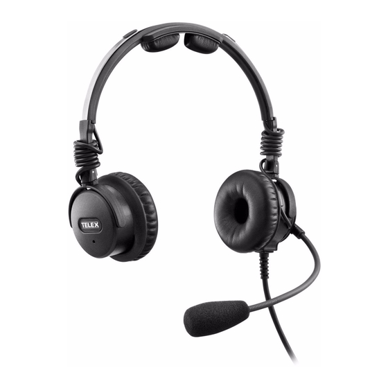
Building on the tradition of the Airman 850, the Airman 8 has improved durability, intelligibility, and comfort. The Airman 8 is among the lightest ANR (Active Noise Reduction) headset on the market and the only FAA approved ANR headset to utilize Telex’s proprietary battery-free, noise-reduction system. -
Page 8: Reference View
8 Introduction & Specifications Airman 8 1.3 Reference View Headband Holder and Headset Slider Ear Cushion Ear Cup Rotator Boom Rotator Cord with Strain Relief Boom Microphone/Windscreen... -
Page 9: Parts List And Disassembly/Assembly
WIRE 28 AWG RED S-F01U342083 F.01U.342.083 CORD UNIT, PJ Y-BLOCK S-F01U342084 F.01U.342.084 EAR SHELL, BOOM SIDE, AIRMAN 8 S-F01U342085 F.01U.342.085 EAR SHELL, NON BOOM SIDE, AIRMAN 8 S-F01U342086 F.01U.342.086 COVER, NON BOOM SIDE, AIRMAN 8 S-F01U342087 F.01U.342.087 SWITCH ACTUATOR, AIRMAN 8 S-F01U342088 F.01U.342.088... -
Page 10: Reference Views
10 Parts List and Disassembly/Assembly Airman 8 S-F01U344923 F.01U.344.923 GLIDER YOKE ASSY, AIRMAN 8 SCREW, PT PAN HEAD K15 X 3.5MM S-F01U344924 F.01U.344.924 (25PCS) ESP-F01U351884 F.01U.359.827 HEADBAND PAD HOLDER S-F01U347879 F.01U.347.879 HEADBAND CLIP (2 PCS) S-F01U348100 F.01U.348.100 HEADBAND COVER AND HEADBAND PAD a. -
Page 11: Disassembly/Assembly
Airman 8 Parts List and Disassembly/Assembly 11 Disassembly/Assembly The following procedure describes the complete disassembly of the Airman 8. IMPORTANT: The removal process requires the following steps be followed in the order described. Assembly is the reversal of the disassembly procedure. Please take care when disassembling •... -
Page 12: Replace Cushions And Windscreen
12 Parts List and Disassembly/Assembly Airman 8 2.3.1.2 Replace Cushions and Windscreen To ensure optimal product performance, it is recommended you replace ear cushions and headband pads periodically (every six months or sooner, if needed). 2.3.1.2.1 Ear Cushion Replacement To replace the ear cushions, do the following: 1. - Page 13 Airman 8 Parts List and Disassembly/Assembly 13 Current Version Headpad Holder and Headpad To replace the headpad holder, do the following: 1. At one end of the headpad holder, carefully pry the holder from the headband cover. NOTE: Carefully twisting slightly on the headpad holder can help remove the piece easier 2.
-
Page 14: Remove The Mic Prefilter
14 Parts List and Disassembly/Assembly Airman 8 2.3.1.3 Remove the mic prefilter To remove the prefilter, do the following: 1. Using your nail, carefully pry the prefilter from the mic. 2.3.1.4 Remove the Yoke Assembly from the Headband Assembly To remove the yoke assembly from the headband assembly, do the following: 1. -
Page 15: Boom Side Disassembly
Airman 8 Parts List and Disassembly/Assembly 15 2.3.1.5 Boom Side Disassembly To remove the speaker assembly and sleeve, do the following: 1. At the same time, push the two retaining cams located in the speaker assembly out of the way. - Page 16 16 Parts List and Disassembly/Assembly Airman 8 4. Remove the housing and the yoke/glider assembly. 5. Using a T-5 screwdriver, remove two screws (as shown). 6. Remove the PCBA.
-
Page 17: Non-Boom Side Disassembly
Airman 8 Parts List and Disassembly/Assembly 17 7. Using a soldering iron, carefully disconnect the wires from the speaker, overhead cord, boom mic assembly, and ANR mic solder terminals, as needed. IMPORTANT: Take care to avoid touching the plastic housing with soldering iron. - Page 18 18 Parts List and Disassembly/Assembly Airman 8 2. Using a T-5 screwdriver, remove three screws (as shown). 3. Remove the housing and the yoke/glider assembly.
- Page 19 Airman 8 Parts List and Disassembly/Assembly 19 4. Using a T-5 screwdriver, remove two screws (as shown). 5. Remove the PCBA. 6. Using a soldering iron, carefully disconnect the wires from the speaker and overhead cord, and ANR mic solder terminals, as needed.
-
Page 20: Assembly
20 Parts List and Disassembly/Assembly Airman 8 2.3.2 Assembly 2.3.2.1 Boom Side Assembly To assemble the boom-side assembly, do the following 1. Solder the overhead cord to PCBA. blue white shield black 2. Solder the cable assembly to PCBA. (See “Wiring Diagram Airman8- 2010 and Airman8-0211”... - Page 21 Airman 8 Parts List and Disassembly/Assembly 21 5. Using the two shorter screws, attach the PCBA to the boom mic assembly(1). NOTE: Take care to route the overhead cord and headset cord through the corresponding grooves provided on the boom (2).
- Page 22 22 Parts List and Disassembly/Assembly Airman 8 8. Route the speaker wires through the housing and solder to the PCBA. white 9. Place yoke on the housing. NOTE: Take care to verify the orientation of the yoke, because it does not rotate 360°.
- Page 23 Airman 8 Parts List and Disassembly/Assembly 23 11. Place the housing on the boom mic assembly. NOTE: Make sure the overhead cord is in the correct slot and the jacket is fully inside the housing. Also, make sure the headset cord is properly located in the housing.
- Page 24 24 Parts List and Disassembly/Assembly Airman 8 13. Position the overhead cord in the retaining clip, and then align the knob of the faceplate toward the bottom. 14. Align the four tabs on the faceplate, and then rotate counterclockwise to lock.
-
Page 25: Non-Boom Side Assembly
Airman 8 Parts List and Disassembly/Assembly 25 15. Carefully wind the overhead cord around the glider 2.3.2.2 Non-Boom Side Assembly To assemble the non-boom side assembly, do the following 1. Solder overhead cord to PCBA. blue white shield black 2. Using the two shorter screws, attach the PCBA to the cover (1). - Page 26 26 Parts List and Disassembly/Assembly Airman 8 3. Solder the wires to the speaker. NOTE: Align the red wire with the polarity dot on the speaker (as shown). 4. Route the speaker wires through the housing and solder to the PCBA.
- Page 27 Airman 8 Parts List and Disassembly/Assembly 27 7. Place the cover on the housing. 8. Using a T-5 screwdriver, replace the three screws (as shown) to attach the yoke and housing to the PCBA.
- Page 28 28 Parts List and Disassembly/Assembly Airman 8 9. Position the overhead cord in retaining clip and align the knob of the faceplate toward the bottom. 10. Align the four tabs (shown) on the faceplate, and then rotate counterclockwise to lock.
-
Page 29: Attach The Mic Prefilter
Airman 8 Parts List and Disassembly/Assembly 29 11. Carefully wind the overhead cord around the glider 2.3.2.3 Attach the mic prefilter To attach the prefilter, do the following: 1. Carefully attach the prefilter to the mic. 2.3.2.4 Reinstall the headband cover To reinstall the headband cover, do the following: 1. -
Page 30: Replace The Yoke Assembly From The Headband Assembly
30 Parts List and Disassembly/Assembly Airman 8 2. Ensure the cover fully encloses around the headband at both sides. 2.3.2.5 Replace the Yoke Assembly from the Headband Assembly To replace the yoke assembly on the headband assembly, do the following: 1. -
Page 31: Replace The Headband Cover Clips (If Present)
Airman 8 Parts List and Disassembly/Assembly 31 2.3.2.6 Replace the headband cover clips (if present) To replace the headband cover clips, do the following: 1. Carefully snap the clip on to the headband. IMPORTANT: Some headsets a snap feature (2) at each end of the headband cover. If this feature... -
Page 32: Replace Cushions And Windscreen
32 Parts List and Disassembly/Assembly Airman 8 2.3.2.7 Replace Cushions and Windscreen To ensure optimal product performance, it is recommended you replace ear cushions and headband pads periodically (every six months or sooner, if needed). 2.3.2.7.1 Ear Cushion Replacement To replace the headband pads, do the following: Early Version Headband 1. - Page 33 Airman 8 Parts List and Disassembly/Assembly 33 5. Firmly press the headband pad into place.
- Page 34 34 Parts List and Disassembly/Assembly Airman 8...
-
Page 35: Maintenance
Troubleshoot and Maintenance The Airman 8 headset is designed so that ANR performance and boom microphone sensitivity can be adjusted as required to meet specification requirements. These are only adjustments that can be made to the headset in order to alter performance. - Page 36 36 Maintenance Airman 8...
-
Page 37: Physical Inspection
Airman 8 Maintenance 37 3.1.2 Physical Inspection 3.1.2.1 Review all plastic parts for cracks or breaks To review plastic parts, do the following: • Note any parts which need to be replaced 3.1.2.2 Review all cables for obvious signs of damage to the insulting... - Page 38 38 Maintenance Airman 8...
-
Page 39: Microphone Troubleshooting And Workflow
3.1.4.3 Microphone/Amplifier Sensitivity Check IMPORTANT: The Airman 8 headset was designed, tested, and approved to FAA TSO C139a. The TSO requires the headset meet the minimum performance specifications as defined in RTCA DO- 214a. This document and specifications listed here reference the test procedures and equipment used as defined in these standards. -
Page 40: Microphone Sensitivity Adjustment
40 Maintenance Airman 8 3.1.4.4 Microphone Sensitivity Adjustment The microphone gain has been factory-adjusted to the nominal level required for normal radio operation. Microphone sensitivity is adjusted by turning the gain adjustment control. To adjust the microphone, do the following: 1. -
Page 41: Speaker Troubleshooting And Workflow
Airman 8 Maintenance 41 3.1.5 Speaker Troubleshooting and Workflow... -
Page 42: Speaker Sensitivity And Frequency Response Verification
Airman 8 3.1.5.1 Speaker Sensitivity and Frequency Response Verification NOTE: The Airman 8 headset was designed, tested, and approved to FAA TSO C139a. The TSO requires the headset meet the minimum performance specifications as defined in RTCA DO-214a. This document and specifications listed here reference the test procedures and equipment used as defined in these standards. -
Page 43: Anr Troubleshooting And Workflow
Airman 8 Maintenance 43 3.1.6 ANR Troubleshooting and Workflow... - Page 44 44 Maintenance Airman 8 The Airman 8 headset was designed, tested, and approved to FAA TSO C139a. The TSO IMPORTANT: requires the headset meet the minimum performance specifications as defined in RTCA DO- 214a. This document and specifications listed here reference the test procedures and equipment used as defined in these standards.
-
Page 45: Cleaning The Headset And Connectors
Airman 8 Maintenance 45 3.1.6.1 Cleaning the Headset and Connectors Do not allow alcohol or any liquid to touch the speaker or microphone element directly. IMPORTANT: To clean the headset, do the following: > Using a mild detergent with water and a soft towel, or isopropyl alcohol wipes, clean the plastic and metal headset parts. -
Page 46: Replacing The Windscreen
46 Maintenance Airman 8 3.1.6.5 Replacing the Windscreen The foam windscreen can be cleaned using low pressure air to blow contaminates off from the exterior, If low pressure air does not provide effective results the windscreen should be replaced. IMPORTANT: Do not use any liquid on the foam windscreen. - Page 47 Airman 8 Maintenance 47 3. Coil the cord into a loop. 4. Place the coiled cord and headset in the carrying case.
- Page 48 48 Maintenance Airman 8...
-
Page 49: Wiring / Connectors
CHAPTER 4 Wiring / Connectors Wiring Diagrams 4.1.1 Wiring Diagram Airman8- 2010 and Airman8-0211 Wire Notes Wire Notes no connection Outside (mic side) outer shield + black Inside white Outside (mic side) inner shield + blue Inside yellow Inside no connection Inside... -
Page 50: Connectors
50 Wiring / Connectors Airman 8 Connectors 4.2.1 PJ-068/PJ055 Connector Diagram for Airman8-0210 PJ-068 and PJ055 Connector Diagram Airman8-0210 FIGURE 2. PJ-068 and PJ055 Wiring Diagram for Airman8-0210 FIGURE 3. PJ-068 or equivalent Description Wiring Color Not Used Ring Mic Signal... -
Page 51: Xlr Connector Diagram For Airman8-0211
Airman 8 Wiring / Connectors 51 4.2.2 XLR Connector Diagram for Airman8-0211 XLR Connector for Airman8-0211 FIGURE 4. Description Wiring Color Headphone Signal Headphone GND Black/Outer Shield Mic Power and Signal White Mic GND and ANR Return Blue/Inner Shield No Connection... - Page 52 Bosch Security Systems, Inc. 12000 Portland Avenue South Burnsville, MN 55337 U.S.A. www.boschcommunications.com...
Need help?
Do you have a question about the Airman 8 and is the answer not in the manual?
Questions and answers