
Related Manuals for CAME BPT LVC/01


Summary of Contents for CAME BPT LVC/01
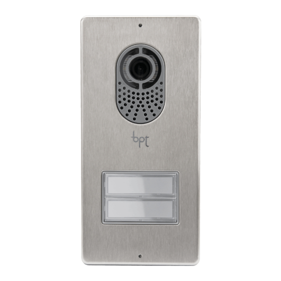
- Page 1 Posto esterno citofonico e FB00562M04 videocitofonico LVC/01 LC/01 IT Italiano LVC/01 - LC/01 EN English FR Français MANUALE DI PROGRAMMAZIONE RU Pусский...
-
Page 2: Avvertenze Generali
1÷10 s. (default 1 s) JUMPER PROG 6 SW3: Abilitazione/disabilitazione funzione interco- municante (vedi paragrafo ‘Programmazione’). Caratteristiche tecniche BOUT Tipo LVC/01 LC/01 Alimentazione (VDC) 16÷18 Assorbimento (mA max) Funzioni Assorbimento in stand by (mA) Morsettiera 1 Dimensioni (mm) -
Page 3: Esempi Di Collegamento
Esempi di collegamento VAS/100 – BOUT – + – VLS/300 VA/01 BIN1 BIN2 BIN3 BOUT +12V – + – VLS/300 BOUT... -
Page 4: Prima Programmazione
PROGRAMMAZIONE DEI POSTI ESTERNI CON VAS/101 Prima Programmazione Ingresso in Programmazione PROG Premere per almeno 3 secondi il tasto PROG 1 e rilasciarlo (entro 6 se- >3’’ <6’’ condi) non appena il LED PROG si accende e la retroilluminazione dei tasti lampeggia come illustrato in figura 2. -
Page 5: Procedura Di Riprogrammazione
Procedura di Riprogrammazione Ingresso in Programmazione PROG >3’’ Premere per almeno 3 secondi il tasto PROG 1 e rilasciarlo (entro 6 s) non <6’’ appena il LED PROG lampeggia e la retroilluminazione dei tasti si accende PROG come illustrato in figura 2. PROG BOUT Programmazione dei tasti di chiamata... -
Page 6: Programmazione Di Un Gruppo Intercomunicante
Programmazione di un gruppo intercomunicante La programmazione del gruppo intercomunicante deve essere effettuata SUCCESSIVAMENTE all’assegna- zione a tutti i derivati interni del tasto di chiamata. Assegnazione dei gruppi intercomunicanti PROG Con il jumper SW3 inserito, premere per almeno 8 s il tasto PROG e rila- >8’’... -
Page 7: Prima Programmazione Con Un Posto Esterno
PROGRAMMAZIONE DEI POSTI ESTERNI CON VA/01 Prima Programmazione con un posto esterno Ingresso in Programmazione Premere il tasto PROG dell’alimentatore 1 finchè il LED PROG si accen- PROG PROG de. La mancata accensione del LED PROG segnala un malfunzionamento. Verificare le connessioni e rientrare in programmazione. Il LED PROG e la >3’’... -
Page 8: Prima Programmazione Con Più Posti Esterni
Prima Programmazione con più posti esterni Ingresso in Programmazione Premere il tasto PROG dell’alimentatore 1 finchè il LED PROG si accende. PROG PROG L’eventuale spegnimento immediato del LED PROG segnala un malfunzio- namento nelle connessioni fra alimentatore e posto esterno. Verificare le >3’’... - Page 9 Procedura di riprogrammazione Ingresso in Programmazione Premere il tasto PROG dell’alimentatore A finchè il LED PROG si accende. PROG PROG Il LED PROG e la retroilluminazione dei tasti lampeggeranno 2. Attendere 5 secondi la conclusione dell’autotest e proseguire come sotto indicato. >3’’...
- Page 10 Premere uno dei tasti di chiamata dei posti esterni da riprogrammare, i LED 1 P.E 2 P.E della retroilluminazione dei tasti di chiamata 8 smetteranno di lampeggia- re. Ripetere l’operazione su tutti i posti esterni da riprogrammare 8 e I. Nel caso si effettui la riprogrammazione su tutti i posti esterni la configura- zione sarà...
- Page 11 Esempi di collegamento LVC/01 VAS/101 LVC/01 VAS/101 VA/01 LVC/01 LC/01 LC/01...
- Page 12 AGATA V-VC AGATA VC/B CL.RES CL.RES MASTER XDV/304 AGATA V-VC AGATA VC/B CL.RES CL.RES SLAVE LVC/01 VAS/101 – BOUT...
- Page 13 VA/01 LVC/01 RS232 +12V BOUT BIN1 BIN2 BIN3 BOUT LC/01 LC/01 BOUT BOUT...
- Page 14 XDV/304 XDV/304 VA/01 VAS/101...
- Page 15 Distanze con cavo VCM/1D Distanze La+Le ≤100 m * La+Le+L1(L2, L3) ≤150 m Lb+Le ≤100 m * Lb+Le+L1(L2, L3) ≤150 m Lc+Le ≤100 m Lc+Le+ L1(L2, L3) ≤150 m Ld+Le ≤100 m Ld+Le+ L1(L2, L3) ≤150 m ≤25 m La+Lb+Lc+Ld+Le+L1+L2+L3 ≤600 m 2x2,5 mm ≤60 m...
- Page 16 CAME S.p.A. Via Martiri Della Libertà, 15 31030 Dosson di Casier - Treviso - Italy tel. (+39) 0422 4940 - fax. (+39) 0422 4941...
-
Page 17: Programming Manual
Audio and video FB00562-EN entry panel LVC/01 LC/01 LVC/01 - LC/01 PROGRAMMING MANUAL EN English... - Page 18 General precautions Important safety instructions: READ CAREFULLY! • Installation, programming, commissioning and maintenance must only be carried out by expert qualified technicians in full • compliance with the regulations in force. Wear anti-static shoes and clothing if working on the electronic circuit board. •...
-
Page 19: Connection Examples
Connection examples VAS/100 – BOUT – + – VLS/300 VA/01 BIN1 BIN2 BIN3 BOUT +12V – + – VLS/300 BOUT... - Page 20 PROGRAMMING ENTRY PANELS WITH VAS/101 Programming for the first time Entering programming mode Press the PROG key for at least 3 seconds 1 and then release it (within PROG >3’’ 6 seconds), as soon as the PROG LED lights up and the key back lighting <6’’...
-
Page 21: Exiting Programming
Reprogramming Going into Programming PROG >3’’ Press the PROG key for at least 3 seconds 1 and then release it (within 6 <6’’ seconds) as soon as the PROG LED flashes and the key back lighting lights PROG up as illustrated in figure 2. PROG BOUT Programming call keys... - Page 22 Programming an intercommunicating group Programming an intercommunicating group must be carried out AFTER assigning the call key to all of the receivers. Assigning intercommunicating groups PROG With the SW3 jumper inserted, press the PROG key for at least 8 seconds >8’’...
- Page 23 PROGRAMMING ENTRY PANELS WITH VA/01 First Programming with one entry panel Going into Programming Press the PROG button on the power supply 1 until the PROG LED lights PROG PROG up. Failure of the PROG LED to light up, indicates a malfunction. Check the connections and return to programming.
- Page 24 First Programming with several entry panels Going into Programming Press the PROG button on the power supply 1 until the PROG LED lights PROG PROG If the PROG LED immediately goes out, this indicates a malfunction in the >3’’ connections between the power supply and the entry panel. Check the connections and return to programming.
- Page 25 Reprogramming Going into Programming Press the PROG key on the power supply A until the PROG LED lights up. PROG PROG The PROG LED and key back lighting will flash 2. Wait 5 seconds for the auto test to be completed and continue as shown below. >3’’...
- Page 26 Press one of the call keys on the entry panels to be reprogrammed, the 1 P.E 2 P.E LEDs backlighting the call keys 8 will stop flashing. Repeat this operation on all the entry panels to be reprogrammed 8 and 9. If all the entry panels are reprogrammed, the configuration will be as shown in figure J.
- Page 27 Connection examples LVC/01 VAS/101 LVC/01 VAS/101 VA/01 LVC/01 LC/01 LC/01...
- Page 28 AGATA V-VC AGATA VC/B CL.RES CL.RES MASTER XDV/304 AGATA V-VC AGATA VC/B CL.RES CL.RES SLAVE LVC/01 VAS/101 – BOUT...
- Page 29 VA/01 LVC/01 RS232 +12V BOUT BIN1 BIN2 BIN3 BOUT LC/01 LC/01 BOUT BOUT...
- Page 30 XDV/304 XDV/304 VA/01 VAS/101...
- Page 31 Distances with VCM/1D cable Distances La+Le ≤100 m * La+Le+L1(L2, L3) ≤150 m Lb+Le ≤100 m * Lb+Le+L1(L2, L3) ≤150 m Lc+Le ≤100 m Lc+Le+ L1(L2, L3) ≤150 m Ld+Le ≤100 m Ld+Le+ L1(L2, L3) ≤150 m ≤25 m La+Lb+Lc+Ld+Le+L1+L2+L3 ≤600 m 2x2.5 mm ≤60 m...
- Page 32 CAME S.p.A. Via Martiri Della Libertà, 15 31030 Dosson di Casier - Treviso - Italy tel. (+39) 0422 4940 - fax. (+39) 0422 4941...
- Page 33 Portier audio/vidéo FB00562-FR externe LVC/01 LC/01 LVC/01 - LC/01 MANUEL DE PROGRAMMATION FR Français...
-
Page 34: Instructions Générales
1 s) PROG CAVALIER 6 SW3 : Activation/désactivation de la fonction d'inter- communication (voir paragraphe « Programmation »). BOUT Caractéristiques techniques Type LVC/01 LC/01 Alimentation (VDC) 16 - 18 Absorption (mA max.) Fonctions Absorption en mode veille Bornier 1... -
Page 35: Exemples De Branchement
Exemples de branchement VAS/100 – BOUT – + – VLS/300 VA/01 BIN1 BIN2 BIN3 BOUT +12V – + – VLS/300 BOUT... -
Page 36: Première Programmation
PROGRAMMATION DES POSTES EXTERNES AVEC VAS/101 Première Programmation Entrée en mode programmation Appuyer pendant au moins 3 secondes sur la touche PROG 1 et la relâ- PROG >3’’ cher (dans les 6 secondes) dès que la LED PROG s’allume et que le rétroé- <6’’... -
Page 37: Procédure De Reprogrammation
Procédure de reprogrammation Entrée en mode programmation PROG >3’’ Appuyer pendant au moins 3 secondes sur la touche PROG 1 et la relâcher <6’’ (dans les 6 secondes) dès que la LED PROG clignote et que le rétroéclairage PROG des touches s’allume comme indiqué sur la figure 2. PROG BOUT Programmation des touches d’appel... - Page 38 Programmation d’un groupe intercommunicant La programmation du groupe intercommunicant doit être effectuée PAR LA SUITE à l’attribution de la touche d’appel à tous les postes internes. Attribution des groupes intercommunicants PROG Avec le cavalier SW3 activé, appuyer pendant au moins 8 s sur la touche >8’’...
- Page 39 PROGRAMMATION DES POSTES EXTERNES AVEC VA/01 Première programmation avec un poste externe Entrée en mode programmation Appuyer sur la touche PROG du groupe d’alimentation 1 dès que la LED PROG PROG PROG s’allume. Le défaut d’allumage de la LED PROG signale un mauvais fonctionnement.
- Page 40 Première programmation avec plusieurs postes externes Entrée en mode programmation Appuyer sur la touche PROG du groupe d’alimentation 1 dès que la LED PROG PROG PROG s’allume. L’éventuelle extinction immédiate de la LED PROG signale un mauvais >3’’ fonctionnement au niveau des branchements entre le groupe d’alimen- tation et le poste externe.
- Page 41 Procédure de reprogrammation Entrée en mode programmation Appuyer sur la touche PROG du groupe d’alimentation A dès que la LED PROG PROG PROG s’allume. La LED PROG et le rétroéclairage des touches clignotent 2. Attendre 5 secondes la conclusion de l’autotest et poursuivre comme >3’’...
- Page 42 Appuyer sur l’une des touches d’appel des postes externes à reprogram- 1 P.E 2 P.E mer, les voyants du rétroéclairage des touches d’appel 8 cesseront de clignoter. Répéter cette opération sur tous les postes externes à repro- grammer 8 et I. En cas d’exécution de la reprogrammation sur tous les postes externes, la configuration sera celle illustrée sur la figure J.
- Page 43 Exemples de branchement LVC/01 VAS/101 LVC/01 VAS/101 VA/01 LVC/01 LC/01 LC/01...
- Page 44 AGATA V-VC AGATA VC/B CL.RES CL.RES MASTER XDV/304 AGATA V-VC AGATA VC/B CL.RES CL.RES SLAVE LVC/01 VAS/101 – BOUT...
- Page 45 VA/01 LVC/01 RS232 +12V BOUT BIN1 BIN2 BIN3 BOUT LC/01 LC/01 BOUT BOUT...
- Page 46 XDV/304 XDV/304 VA/01 VAS/101...
- Page 47 Distances avec câble VCM/1D Distances La+Le ≤100 m * La+Le+L1(L2, L3) ≤150 m Lb+Le ≤100 m * Lb+Le+L1(L2, L3) ≤150 m Lc+Le ≤100 m Lc+Le+ L1(L2, L3) ≤150 m Ld+Le ≤100 m Ld+Le+ L1(L2, L3) ≤150 m ≤25 m La+Lb+Lc+Ld+Le+L1+L2+L3 ≤600 m 2x2,5 mm ≤60 m...
- Page 48 CAME S.p.A. Via Martiri Della Libertà, 15 31030 Dosson di Casier - Treviso - Italy tel. (+39) 0422 4940 - fax. (+39) 0422 4941...
- Page 49 Вызывная аудио- FB00562-RU и видеопанель LVC/01 LC/01 LVC/01 - LC/01 РУКОВОДСТВО ПО ПРОГРАММИРОВАНИЮ RU Pусский...
-
Page 50: Общие Предупреждения
Звук микрофона Электрозамок 1-10 с (по умолчанию 1 сек.) ПЕРЕМЫЧКА PROG 6 SW3: Активация/отключение функции интерко- ма (см. пункт «Программирование»). Технические характеристики BOUT Модель LVC/01 LC/01 Электропитание (=В) 16-18 Макс. потребляемый ток Функции (мА) Потребление в режиме ожи- Клеммная колодка 1 дания... -
Page 51: Варианты Подключения
Варианты подключения VAS/100 – BOUT – + – VLS/300 VA/01 BIN1 BIN2 BIN3 BOUT +12V – + – VLS/300 BOUT... - Page 52 ПРОГРАММИРОВАНИЕ ВЫЗЫВНЫХ ПАНЕЛЕЙ С VAS/101 Первое программирование Вход в режим программирования Нажмите и удерживайте не менее 3 секунд кнопку PROG 1. Отпусти- PROG >3’’ те ее (спустя не более 6 секунд), как только загорится светодиодный <6’’ индикатор PROG и подсветка клавиш замигает так, как показано на PROG рисунке...
- Page 53 Процедура перепрограммирования Вход в режим программирования PROG >3’’ Нажмите и удерживайте не менее 3 секунд кнопку PROG 1. Отпусти- <6’’ те ее (спустя не более 6 секунд), как только замигает LED-индикатор PROG PROG и подсветка клавиш не загорится так, как показано на рисунке PROG BOUT Программирование...
- Page 54 Программирование группы интерком Программирование группы интеркома должно выполняться ПОСЛЕ присвоения всем абонентским устройствам клавиши вызова. Присвоение групп интеркома PROG С установленной перемычкой SW3 нажмите и удерживайте не менее 8 >8’’ <11’’ секунд кнопку PROG. Отпустите ее (спустя не более 11 секунд) 1, как только...
- Page 55 ПРОГРАММИРОВАНИЕ ВЫЗЫВНЫХ ПАНЕЛЕЙ С VA/01 Программирование с одной вызывной панелью Вход в режим программирования Нажмите и удерживайте кнопку PROG на контроллере 1 до тех пор, PROG PROG пока не загорится светодиодный индикатор PROG. Если индикатор PROG не загорается, это указывает на неполадку. Проверьте подклю- >3’’...
- Page 56 Программирование с несколькими вызывными панелями Вход в режим программирования Нажмите и удерживайте кнопку PROG на контроллере 1 до тех пор, PROG PROG пока не загорится светодиодный индикатор PROG. Выключение LED-индикатора PROG указывает на неисправность под- >3’’ ключений между контроллером и вызывной панелью. Проверьте под- ключения...
- Page 57 Процедура повторного программирования Вход в режим программирования Нажмите и удерживайте кнопку PROG на контроллере A до тех пор, PROG PROG пока не загорится светодиодный индикатор PROG. Светодиодный ин- дикатор PROG и подсветка кнопок замигают 2. Подождите 5 секунд >3’’ для завершения автотеста и выполните описанные ниже действия. 1 P.E 2 P.E beep...
- Page 58 Нажмите одну из клавиш вызова программируемых вызывных па- 1 P.E 2 P.E нелей: светодиоды подсветки клавиш вызова 8 перестанут мигать. Повторите процедуру на всех программируемых вызывных панелях 8 и I. Если выполняется программирование всех вызывных панелей, конфи- гурация будет такой, какая изображена на рисунке J. BOUT BOUT Для...
- Page 59 Варианты подключения LVC/01 VAS/101 LVC/01 VAS/101 VA/01 LVC/01 LC/01 LC/01...
- Page 60 AGATA V-VC AGATA VC/B CL.RES CL.RES MASTER XDV/304 AGATA V-VC AGATA VC/B CL.RES CL.RES SLAVE LVC/01 VAS/101 – BOUT...
- Page 61 VA/01 LVC/01 RS232 +12V BOUT BIN1 BIN2 BIN3 BOUT LC/01 LC/01 BOUT BOUT...
- Page 62 XDV/304 XDV/304 VA/01 VAS/101...
- Page 63 Допустимые расстояния с кабелем VCM/1D Расстояния La+Le ≤100 м * La+Le+L1(L2, L3) ≤150 м Lb+Le ≤100 м * Lb+Le+L1(L2, L3) ≤150 м Lc+Le ≤100 м Lc+Le+ L1(L2, L3) ≤150 м Ld+Le ≤100 м Ld+Le+ L1(L2, L3) ≤150 м ≤25 м La+Lb+Lc+Ld+Le+L1+L2+L3 ≤600 м...
- Page 64 CAME S.p.A. Via Martiri Della Libertà, 15 31030 Dosson di Casier - Treviso - Italy tel. (+39) 0422 4940 - fax. (+39) 0422 4941...
Need help?
Do you have a question about the LVC/01 and is the answer not in the manual?
Questions and answers