Table of Contents
Advertisement
Fidelio System
Wireless Device for the Hearing and Visually Impaired
Installation & User Manual
Version 1.5
The English version of this document is the only legally binding version.
Translated versions are not legally binding and are for convenience only.
FDO.OM.001852.DRM
Page 1 of 77
Version 1.5
Doremi Labs
Advertisement
Table of Contents

Related Manuals for Doremi Fidelio


Summary of Contents for Doremi Fidelio
- Page 1 Fidelio System Wireless Device for the Hearing and Visually Impaired Installation & User Manual Version 1.5 The English version of this document is the only legally binding version. Translated versions are not legally binding and are for convenience only. FDO.OM.001852.DRM Page 1 of 77 Version 1.5...
-
Page 2: Table Of Contents
Brief Description ......................12 Fidelio Transmitter ..........................12 2.1.1 2.1.2 Fidelio Receiver ........................... 13 2.1.3 Fidelio Configuration/Charging Station and Tablet ................ 14 Fidelio Configuration/Charging Station and Tablet ................ 15 2.1.4 Fidelio Audio Interface ........................17 2.1.5 Installation ......................... 18 Charging Station/Touchscreen Tablet ................ 18 Connection of the Tablet Bracket to the Configuration/Charging Station Base ...... - Page 3 Fidelio Audio Interface Connections ................29 3.3.1 Server to Audio Interface and then to Theater Sound Processor ..........29 3.3.1.1 DB25 Connector Setup ......................29 Audio Interface to Fidelio ......................30 3.3.1.2 RJ45 Connector Setups ......................30 3.3.1.3 Audio Interface to Fidelio ......................31 3.3.1.4...
- Page 4 Fidelio Tablet – v1.1.2 ....................52 Fidelio Tablet – v2.2.0 ....................55 Troubleshooting ....................58 10.1 Generating a Detailed Report ..................58 10.2 Updating the Fidelio Touchscreen Tablet Software ..........61 Installation and Update ........................62 10.2.1 10.3 Updating the Fidelio Receiver Firmware ..............66 10.3.1...
- Page 5 Software License Agreement The software license agreement can be found at the following location: http://www.doremilabs.com/support/cinema-support/cinema-warranties/ Hardware Warranty The hardware warranty can be found at the following location: http://www.doremilabs.com/support/cinema-support/cinema-warranties/ FDO.OM.001852.DRM Page 5 of 77 Version 1.5 Doremi Labs...
- Page 6 Never use a DC power supply. If water or any other liquid is spilled into or onto the Fidelio, disconnect the power and call a Doremi dealer. The unit must be well ventilated and away from direct sunlight. To avoid damage to internal circuitry, as well as the external finish, keep the Fidelio away from direct sources of heat (heater vents, stoves, radiators).
- Page 7 FCC Warning - Fidelio Transmitter and Receiver (Fidelio TX / Fidelio RX) Be aware that any change or modification not expressly approved by Doremi Labs could void the user's authority to operate the equipment. This device complies with part 15 of the FCC Rules. Operation is subject to the following...
- Page 8 à l'intention des autres utilisateurs, il faut choisir le type d'antenne et son gain de sorte que la puissance isotrope rayonnée équivalente (p.i.r.e.) ne dépasse pas l'intensité nécessaire à l'établissement d'une communication satisfaisante. FDO.OM.001852.DRM Page 8 of 77 Version 1.5 Doremi Labs...
- Page 9 FDO.OM.001852.DRM Page 9 of 77 Version 1.5 Doremi Labs...
-
Page 10: Introduction
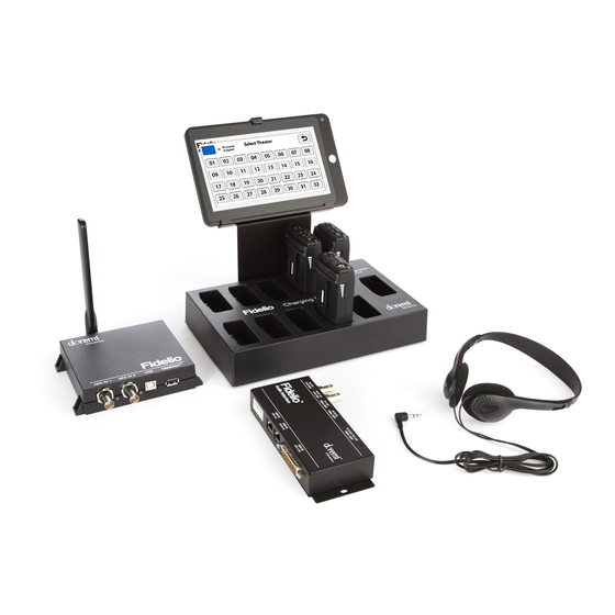
This manual will guide you through the steps necessary to physically set up and connect the Fidelio device. The entire Fidelio setup consists of a Transmitter, Receiver, Charging/Configuration Station, Touch Screen Tablet, Audio Interface Box and Headset. -
Page 11: Requirements
Fidelio Audio Interface box. Contact Information If in need of help or assistance, please contact your nearest Doremi Labs Technical Support at: 24/7 Technical Support line: + 1-866-484-4004 Technical Support Email: support@doremicinema.com... -
Page 12: Overview
2.1.1 Fidelio Transmitter The Fidelio Transmitter is the device that will transmit the Hearing Impaired (HI) or Visually Impaired Narrative (VI-N) audio track from the Digital Cinema Package (DCP) to the Fidelio Receiver (Figure 1). You will need one Fidelio Transmitter for every auditorium you choose to enable. -
Page 13: Fidelio Receiver
2.1.2 Fidelio Receiver The Fidelio Receiver (Figure 2 and Figure 3) is the device that an audience member obtains from the theater customer service kiosk. This receiver is to be configured using the touchscreen tablet interface for the auditorium number that is enabled for Fidelio transmission. The patron then takes the receiver into the assigned auditorium to receive the transmission from the Fidelio Transmitter that has been configured for that assigned auditorium within the multiplex. -
Page 14: Fidelio Configuration/Charging Station And Tablet
2.1.3 Fidelio Configuration/Charging Station and Tablet The Fidelio configuration/charging stations are used to charge and configure Fidelio receivers. The touchscreen tablet (original tablet v1.1.2 - Figure 4) is used to display the graphical user interface (GUI) when configuring each receiver. Refer to Figure 5 for configuration/charging station containing the latest version of the Fidelio tablet. -
Page 15: Fidelio Configuration/Charging Station And Tablet
Figure 6: Fidelio Configuration/Charging Station - Side View Receiver Configuration Receiver Port Charging Ports Figure 7: Fidelio Configuration/Charging Station - Top View Tablet (v. 1.1.2) Home Button Figure 8: Fidelio Tablet (v. 1.1.2) – Front View FDO.OM.001852.DRM Page 15 of 77 Version 1.5 Doremi Labs... - Page 16 Figure 9: Fidelio Tablet (V2.2.0) – Front View HDMI Port Charging Port Not Used On/Off Power Button Mini USB Port MicroSD Headphone Card Port Jack (Not Used) Figure 10: Fidelio Tablet (v1.1.2 – Side View) Headphone Jack (Not Used) HDMI Port...
-
Page 17: Fidelio Audio Interface
AES THRU Connector AES Ch. 1-6, Ch. 9- OUT CH 7/8 RJ45 Port AES THRU CH 1-6 Figure 12: Fidelio Audio Interface – Front View RJ45 Port AES IN CH DB25 Connector 9-16 AES IN CH 1-16 RJ45 Port AES IN CH Figure 13: Fidelio Audio Interface –... -
Page 18: Installation
3.1.1 Connection of the Tablet Bracket to the Configuration/Charging Station Base Place the Fidelio configuration/charging station base upside down near the edge of a table so that the tablet bracket can hang down and sit flush to the bottom of the base. ... -
Page 19: Power Supply Connection
“DC IN 5V,” which is located on the right-hand side of the touchscreen tablet (v.1.1.2 Figure 16; v2.2.0 Figure 17). DC IN 5V Tablet Power Connector Micro USB Cable Figure 16: Tablet (v1.1.2) Power Connector FDO.OM.001852.DRM Page 19 of 77 Version 1.5 Doremi Labs... - Page 20 Using a 4” Nylon black tie-wrap provided, slip the tie-wrap though the eyelet (Figure 18) to secure the cable to the tablet mounting bracket. Cable Tie-Wrap Eyelet Figure 18: Eyelet for Cable Tie-Wrap FDO.OM.001852.DRM Page 20 of 77 Version 1.5 Doremi Labs...
-
Page 21: Usb Cable
Figure 19: USB Connectors Plug the large end (Type B) of the USB cable into the Fidelio configuration/charging station base and the smaller end (Type Mini B) into the micro USB port located on the right-hand side of the Fidelio touchscreen tablet (Figure 19 and Figure 20). This USB cable connection is essential to configuring Fidelio Receivers to specific auditoriums along with their audio channel assignments. - Page 22 USB (Type Mini B) Cable USB (Type B) Cable Figure 20: Fidelio Charging Station and Tablet (v1.1.2) Micro-USB Cable USB (Type B) Cable Figure 21: Fidelio Charging Station and Tablet (v2.2.0) FDO.OM.001852.DRM Page 22 of 77 Version 1.5 Doremi Labs...
-
Page 23: Charging The Receiver Batteries
Upon the initial set up, each Fidelio Transmitter will need to be assigned to a specific auditorium. To perform this operation, plug the large end (Type B) of the USB cable into the Fidelio Transmitter and the smaller end (Type Mini B) into the micro USB port located on the right-hand side of the Fidelio touchscreen tablet (Figure 20). - Page 24 After the Fidelio touchscreen tablet has finished booting up, you will need to unlock the screen by using your finger on the unlock padlock icon and sliding the unlock padlock icon in the up direction on the touch screen (Figure 22).
- Page 25 Home Icon Figure 24: Fidelio Application Icon At first you will see a message saying, “Looking for Fidelio Devices” (Figure 25). Next, you will see a message saying, “Identifying Fidelio Device.” Figure 25: Looking for Fidelio Devices Screen FDO.OM.001852.DRM...
- Page 26 Once the Fidelio Transmitter is recognized, a screen will appear that will indicate what auditorium number has been assigned to the transmitter. Simply touch the Change button on the screen to change the auditorium assignment (Figure 26). Figure 26: Transmitter Change Auditorium Screen Note: The frequency band is configured at factory and cannot be changed by the user.
- Page 27 Follow the same steps mentioned above. Once you have configured all your Fidelio transmitters, power down the Fidelio tablet by depressing and holding the tablet Power button until the Power Off option appears on the tablet screen (Figure 28).
-
Page 28: Connections In Projection Booth
Adapter provided or to one of the USB ports on the Digital Cinema Server. If you are using the USB Power Adapter, plug this into an AC outlet. One of these connections will provide power to the Fidelio Transmitter box. FDO.OM.001852.DRM Page 28 of 77 Version 1.5... -
Page 29: Captiview
USB cable for the CaptiView transmitter to transmit the CC (Closed Captioned) information to the CaptiView Display(s) in the auditorium. The CaptiView transmitter shall at least be 20cm away from the Fidelio transmitter antenna – usage of a USB extension cable will be needed for the CaptiView transmitter connection. -
Page 30: Audio Interface To Fidelio
Using the short RJ45 cable provided, connect one cable into the CH 1-8 AES OUT on the Doremi IMB and the other end into the AES IN CH 1-8 connector on the Fidelio Audio Interface box. Using the other short RJ45 cable provided, connect one cable into the CH 9-16 AES OUT on the Doremi IMB and the other end into the AES IN CH 9-16 connector on the Fidelio Audio Interface box. -
Page 31: Audio Interface To Fidelio
3.3.1.4 Audio Interface to Fidelio You will now need to connect one BNC cable (NOT provided) to the Fidelio Audio Interface Box BNC connector labeled, “AES OUT CH 15/16” (Figure 34). Connect the other end of this BNC cable to the Fidelio Transmitter box BNC connector labeled, “AES IN 2”... -
Page 32: Assigning The Receiver To An Auditorium
First you will need to plug the large end (Type B) of the USB cable into the USB port located on the right-hand side of the Fidelio charging station base and the smaller end (Mini A) into the micro USB port located on the right-hand side of the Fidelio touchscreen tablet (Figure 20). - Page 33 (Figure 36). Figure 36: Receiver Auditorium Assignment Screen With your finger, touch the theater number you wish to assign to the Fidelio receiver that is plugged into the Configuration Port. The tablet will then display the Receiver screen (Figure 37).
- Page 34 Ch.2 (Stereo) The selection you make will be based on your Fidelio wiring setup and your Digital Cinema Player's audio mapping. In other words, assuming that you use the audio wiring setup as described in this manual, and the Digital Cinema Package playing back has...
-
Page 35: Accessibility Track Mapping
Figure 39: Interop/ISDCF Recommendations Doremi Server Audio Channel Re-Mapping The following will assist you to re-map your audio on the Doremi Cinema Player. To open the Audio Configuration application, go to Menu → Control Panel → Audio Configuration (Figure 40). - Page 36 Custom. Once the template is edited, the Template Mapping will read Custom. Available configurations include: Disabled: This setting is the default and as such cannot be mapped (Section 5.2.1.1). FDO.OM.001852.DRM Page 36 of 77 Version 1.5 Doremi Labs...
-
Page 37: Channel Mapping Tab
Ch.03 is Center (C): Output ch.03 will be playing the CPL's Center (C) audio channel. Ch.04 is Input: ch.04 is pass-through, meaning the output channel “X” will be playing the CPL's audio channel “X.” FDO.OM.001852.DRM Page 37 of 77 Version 1.5 Doremi Labs... -
Page 38: Channels
Ch.15 is HI: Output ch.15 will be playing the CPL's Hearing Impaired (HI) audio channel. Ch.16 is VI: Output ch.16 will be playing the CPL's Narration (VI) audio channel. FDO.OM.001852.DRM Page 38 of 77 Version 1.5 Doremi Labs... -
Page 39: Channels
Ch.15 is HI: Output ch.15 will be playing the CPL's Hearing Impaired (HI) audio channel. Ch.16 is VI: Output ch.16 will be playing the CPL's Narration (VI) audio channel. FDO.OM.001852.DRM Page 39 of 77 Version 1.5 Doremi Labs... -
Page 40: Channels
Ch.15 is HI: Output ch.15 will be playing the CPL's Hearing Impaired (HI) audio channel. Ch.16 is VI: Output ch.16 will be playing the CPL's Narration (VI) audio channel. FDO.OM.001852.DRM Page 40 of 77 Version 1.5 Doremi Labs... -
Page 41: Channels
Ch.15 is HI: Output ch.15 will be playing the CPL's Hearing Impaired (HI) audio channel. Ch.16 is VI: Output ch.16 will be playing the CPL's Narration (VI) audio channel. FDO.OM.001852.DRM Page 41 of 77 Version 1.5 Doremi Labs... -
Page 42: Isdcf
Ch.12 is Right Rear Surround (Rrs): Output ch.12 will be playing the CPL's Right Rear Surround (Rrs) audio channel. Ch.13 is Input: ch.13 is pass-through, meaning the output channel “X” will be playing the CPL's audio channel “X.” FDO.OM.001852.DRM Page 42 of 77 Version 1.5 Doremi Labs... -
Page 43: Custom Mapping Configuration
Figure 48: Audio Mapping Set to ISDCF 5.2.1.3 Custom Mapping Configuration Click on the drop-down menu and select Custom. The following window will appear (Figure 49). Figure 49: Custom Mapping FDO.OM.001852.DRM Page 43 of 77 Version 1.5 Doremi Labs... -
Page 44: Advanced Tab
After the delay has been configured, click on the Save button to save the audio delay. The selected audio delay is shown in numeric characters below the cursor field (Figure 51). Figure 51: Advanced Tab FDO.OM.001852.DRM Page 44 of 77 Version 1.5 Doremi Labs... -
Page 45: Smpte Packages
The list of possible labels that can be routed (if present in the audio MXF file) are defined by SMPTE as follows: L/Left R/Right C/Center LFE Screen Ls/Left surround Rs/Right surround Lc/Left center Rc/Right center Cs/Center surround Rrs/Right rear surround Lrs/Left rear surround HI/Hearing Impaired VI-N/Visual Impaired-Narration FDO.OM.001852.DRM Page 45 of 77 Version 1.5 Doremi Labs... -
Page 46: Digital Cinema Naming Convention
The following will assist you in determining if a DCP has been mastered to include the Hearing Impaired (HI) and Visually Impaired Narrative (VI-N) audio track(s). Figure 52: Digital Cinema Naming Convention - v9 FDO.OM.001852.DRM Page 46 of 77 Version 1.5 Doremi Labs... - Page 47 Note: All other Appendix information referred to in Figure 52 can be found at www.digitalcinemanamingconvention.com. FDO.OM.001852.DRM Page 47 of 77 Version 1.5 Doremi Labs...
-
Page 48: Technical Specs
Number of channels selectable via configuration At least 20 auditoria x[2 stereo channels and text] Battery life at full audio volume (new battery) 12 hours Battery charging Charging connection studs on Fidelio FDO.OM.001852.DRM Page 48 of 77 Version 1.5 Doremi Labs... -
Page 49: Led Lights Description
Steady On Device is turned on, and the battery is OK. On, with a brief off Device is turned on, and the period every 2 battery is low. seconds. FDO.OM.001852.DRM Page 49 of 77 Version 1.5 Doremi Labs... - Page 50 2 configured. seconds Both LEDs flash Incorrect configuration data or rapidly, 5 times per radio uncalibrated. second Both LEDs flash In radio test mode. very rapidly, 10 times per second FDO.OM.001852.DRM Page 50 of 77 Version 1.5 Doremi Labs...
-
Page 51: Transmitter Unit Leds
Incorrect configuration data, or times per second radio uncalibrated, or (on the Slave channel) not synchronized to the Master channel. Flashing very In radio test mode. rapidly, 10 times per second FDO.OM.001852.DRM Page 51 of 77 Version 1.5 Doremi Labs... -
Page 52: Fidelio Micro Sd Card Replacement
Figure 55: Fidelio Tablet – Micro SD Slot Insert the micro SD card into the Fidelio Tablet while making sure the top of the micro SD card is upright and the copper contacts on the backside go into the slot first (Figure 55 and Figure 56). - Page 53 Use your finger nail or a non-metallic tool to push the micro SD card completely into the slot on the Fidelio Tablet (Figure 57). You will hear a click when the micro SD card has been installed successfully. Figure 57: Non-Metallic Tool ...
- Page 54 The micro SD replacement procedure is now complete. Test the system by plugging a receiver into the Fidelio receiver port. All the auditorium assignments will be displayed. If experiencing any technical difficulties, please contact Doremi Labs Technical Support (Section 1.4).
-
Page 55: Fidelio Tablet - V2.2.0
Use your finger nail or a non-metallic tool to push the micro SD card completely into the slot on the Fidelio Tablet (Figure 63). You will hear a click when the micro SD card has been installed successfully. FDO.OM.001852.DRM Page 55 of 77 Version 1.5... - Page 56 Once the micro SD card has been installed successfully, power up the Fidelio touchscreen tablet. Once the tablet is booted up fully, find and select the Fidelio application from the menu of applications. A message stating, “NO SD Card,” will appear (Figure 58): Figure 64: Files Don’t Match Window...
- Page 57 The micro SD replacement procedure is now complete. Test the system by plugging a receiver into the Fidelio receiver port. All the auditorium assignments will be displayed. If experiencing any technical difficulties, please contact Doremi Labs Technical Support (Section 1.4).
-
Page 58: Troubleshooting
Session ID In the event that diagnostics are required, you may be asked to provide a Detailed Report from the Fidelio System. To do so launch the Diagnostic Tool application (Figure 66), and using the mini USB to standard USB connector, connect a USB Thumb Drive. - Page 59 Next, press the Detailed Report icon that appears on the screen (Figure 67). Figure 67: Detailed Report Button You will see a confirmation message that the report is being generated (Figure 68). Figure 68: Generating Report FDO.OM.001852.DRM Page 59 of 77 Version 1.5 Doremi Labs...
- Page 60 Press the OK button to complete the process (Figure 69). It is this .tgz report that you will need to forward to an authorized Doremi Service Center for further diagnostics. Depress the Home button (Refer to Figure 8 for v1.1.2; Refer to Figure 24 for v2.2.0) to return to the Applications Screen.
-
Page 61: Updating The Fidelio Touchscreen Tablet Software
Figure 70: Report Not Generated Successfully 10.2 Updating the Fidelio Touchscreen Tablet Software Application Manager: This application is used for updating the Fidelio tablet to a new version when required (Figure 71). Application Manager Figure 71: Application Manager FDO.OM.001852.DRM Page 61 of 77 Version 1.5... -
Page 62: Installation And Update
10.2.1 Installation and Update Using the mini USB to standard USB connector, connect a USB drive containing the Fidelio update to the tablet (Figure 72). Wait for a few seconds while the drive's package list updates. Figure 72: USB Key ... - Page 63 The app will ask you to reboot the tablet. Select Yes and then remove the USB key (Figure 75). The tablet will reboot. Figure 75: Reboot Warning FDO.OM.001852.DRM Page 63 of 77 Version 1.5 Doremi Labs...
- Page 64 Once the tablet boots back up, unlock the tablet. The home page will be displayed (Figure 76). The new application, Fidelio FW Update, has been added to the home page. Figure 76: Home Pages To confirm that the software has been updated, go to Diagnostic Tools and check that the software version is 1.1.8 or higher (Figure 77).
- Page 65 In the event a transmitter or receiver is not recognized by the Fidelio touchscreen tablet or base configuration port, try one or all of the following troubleshooting tips: Verify that you have the correct wiring configuration. For transmitter wiring, see Section 3.
-
Page 66: Updating The Fidelio Receiver Firmware
Note: For information on the latest firmware, please contact Doremi Labs Technical Services. Go to the Fidelio FW Update app on the Tablet's home page. It will scan all available firmware packages on the USB drive (Figure 78). Import... - Page 67 Tap OK, and then go back to the Fidelio FW Update page. Unplug the USB drive and connect the Fidelio Charging Station to the tablet through a USB cable. Put one of the Fidelio receivers into the Configuration Port in the Fidelio Charging Station (Figure 82).
- Page 68 Tap the Flash FW button (Figure 83). Confirm the flashing process by tapping on the Flash button (Figure 85). Flash Button Figure 85: Flash Firmware Window The process of flashing will take 1-2 minutes to flash the Fidelio Receiver (Figure 86). FDO.OM.001852.DRM Page 68 of 77 Version 1.5 Doremi Labs...
- Page 69 Once the flashing is done, a message window will tell the user that the flash is successful and complete (Figure 87). Figure 87: Successful Flash Window This Fidelio Receiver firmware procedure is now complete FDO.OM.001852.DRM Page 69 of 77 Version 1.5...
-
Page 70: Updating The Fidelio Transmitter Firmware
Note: For information on the latest firmware, please contact Doremi Labs Technical Services. Go to the Fidelio FW Update app on the Tablet's home page. It will scan all available firmware packages on the USB drive (Figure 88). Import... - Page 71 Tap OK, and then go back to the Fidelio FW Update page. Unplug the USB drive and connect the Fidelio transmitter to the tablet through a USB cable (Figure 92 and Figure 93Figure 82). Figure 92: USB Cable FDO.OM.001852.DRM...
- Page 72 Figure 93: Fidelio Transmitter Under the section titled, Available Firmwares on SD Card, the imported firmwares will be displayed (Figure 83). Flash FW Button Firmware Information Button Figure 94: Available Firmwares Go to the Firmware Information button (Figure 94) to make sure that the firmware version that you will be flashing is the desired one.
- Page 73 Button Figure 96: Flash Firmware Window The process of flashing will take 1-2 minutes to flash the Fidelio Transmitter (Figure 97). Figure 97: Flashing Progress Window Once the flashing is done, a message window will tell the user that the flash is successful and complete (Figure 98).
-
Page 74: Appendix A: Wiring Guide
11 Appendix A: Wiring Guide FDO.OM.001852.DRM Page 74 of 77 Version 1.5 Doremi Labs... - Page 75 FDO.OM.001852.DRM Page 75 of 77 Version 1.5 Doremi Labs...
-
Page 76: Acronyms
Acronyms Term Definition Audio Engineering Society DB25 D-Sub-miniature Digital Cinema Package Hearing Impaired Light Emitting Diode VI-N Visually Impaired Narrative FDO.OM.001852.DRM Page 76 of 77 Version 1.5 Doremi Labs... -
Page 77: Document Revision History
Document Revision History Date Revision Description 11/01/2011 First version. 05/03/2012 New FCC warnings added. New Doremi logo added. New screen shots for version 1.1.5 added. 05/13/2013 Section 11 added and revisions made to Sections 3.1.5 and 7.1. 10/15/2013 Section 10 updated.
Need help?
Do you have a question about the Fidelio and is the answer not in the manual?
Questions and answers