Table of Contents
Advertisement
Advertisement
Table of Contents

Related Manuals for Panasonic LIQI


Summary of Contents for Panasonic LIQI
- Page 1 Panasonic LIQI...
- Page 2 Interface wiring diagram COM+ Servo-on input SER-ON PULS1 Command Alarm clear input A-CLR PULS2 Pulse Counter clear input SIGN1 Input Inhibit input SIGN2 CW over travel inhibition input Output Pulses CCW over travel inhibition input Servo Alarm output Servo ready output S-RDY Brake release output Signal Ground,...
- Page 3 C : Size C 20 : 20A 07 : 7A 10 : 10A 30 : 30A AC servo drive J : LIQI series Maximum Power supply rating instantaneous current 2 : Single phase 220V T3 : 30A T2 : 15A...
- Page 4 Basic Features • Input power range : AC 220V (200V ~ 253V) • Motor rating : MHMD***J1* 200W/1.0kW MHMJ***P1* 400W/750W/1.0kW / 1.2kW • Control mode : Position command • Response frequency : 1kHz • Pulse command up to 500kHz • Advanced PANATERM software •...
- Page 5 MINAS-LIQI can 1.Perform quick and stable machine operation 1.Perform quick and stable machine operation 2500ppr 500KPPS Encoder Response frequency Input/Output pulse Lower cogging torque 2.Minimize vibration & noise 2.Minimize vibration & noise Notch Filter Adaptive Filter Real auto tuning 3 Offer serviceable accessary...
- Page 6 1. High Response 3. Compact 500Hz Response frequency New Structure 2500 ppr encoder Innovative Core resolution Low cogging Innovation torque Encoder The I/O pulses 500kHz 4. Easy 2. Intelligent Set up support software “PANATERM Highly functional Real-time Auto- Motor Selection Gain tuning Software Manual/Auto...
- Page 7 Rated Voltage Size Part Number Motor Output MSMD5AZJ1* 100W MSMD012J1* MBDJT2207 MSMD022J1* Type B 200W MHMD022J1* MSMD042J1* MBDJT2210 400W MHMJ042P1* AC220-240V MSMD082J1* MCDJT3220 750W MHMJ082P1* MHMD102J1* Type C 1000W MCDJT3230 MHMJ102P1* 1200W MHMJ122P1* Motor Business Unit, Home Appliances Company, Panasonic...
- Page 8 Overvoltage, undervoltage, over speed, overload, overheat, over current, encoder error, etc. Protective Function Software error Following error fault, command pulse scaling error, EEPROM error, etc. Alarm data trace back Tracing back of alarm data is available Motor Business Unit, Home Appliances Company, Panasonic...
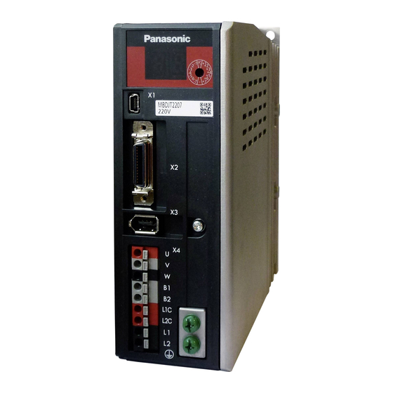
- Page 9 5. Appearance and Part Names 220V Size B X1 USB Connection X2: Parallel I/O Connection X3: Encoder Connection X Motor Connection Power Supply Connection Connection Terminal Power Supply Input Terminal Power Supply Input Terminal Motor Business Unit, Home Appliances Company, Panasonic...
- Page 10 SR-DSV10739 - 5 - 220V Size C X1 USB Connection X2: Parallel I/O Connection X3: Encoder Connection X Motor Connection Power Supply Connection Connection Terminal Power Supply Input Terminal Power Supply Input Terminal Motor Business Unit, Home Appliances Company, Panasonic...
- Page 11 Description or Pin Circui Multi-function input 1 Multi-function input 2 Multi-function input 3 - The function changes according to the parameter settings. See below. Multi-function input 4 Multi-function input 5 Multi-function input 6 Motor Business Unit, Home Appliances Company, Panasonic...
- Page 12 : Input signal disconnected from COM-function disabled (OFF state) Input signal connected to COM-function enabled (ON state) b-contact :Input signal disconnected from COM-function enabled (ON state) Input signal connected to COM function disabled (OFF state) Motor Business Unit, Home Appliances Company, Panasonic...
- Page 13 Incorrect setting will cause Err33.0 I/F input multiple assignment error 1 or Err33.1 I/F input multiple assignment error 2. *3 Deviation counter clear input(CL)can be assigned only to SI7 input. Wrong assignment will cause Err33.6 Counter clear assignment error. Motor Business Unit, Home Appliances Company, Panasonic...
- Page 14 Output signals (Common) and their functions Connector Description Name Symbol Circuit Pin No. Multi-function output 1 - The function changes according to the parameter settings. See below. Multi-function output 2 Multi-function output 3 Motor Business Unit, Home Appliances Company, Panasonic...
- Page 15 ** with the function number. 0 00FFFFFFh SO2 output selection Assign functions to SO2 to SO3 outputs. These parameters are presented in hexadecimals. 0 00FFFFFFh SO3 output selection Setup procedure is the same as described for Pr.4.00. Motor Business Unit, Home Appliances Company, Panasonic...
- Page 16 0.5A or more is recommended. Shell Frame ground - Internally connected to the earth terminal. - Signal ground Signal ground - Internally insulated from the control signal power supply (COM-). - Don’t connect, please Reserved 24/25 Motor Business Unit, Home Appliances Company, Panasonic...
- Page 17 Note If you want to directly driver a relay,In parallel with the relay. Please install the diode in the direction shown above. VCE sat = 1.2V 2,3,4,5,6,7 pin Equi val ent For open c ollec tor 12,15,17pin 14,16,18 pin 2022 21. 23 Motor Business Unit, Home Appliances Company, Panasonic...
- Page 18 Ferrule pin of DNH4 -112 made in DINKEL (4mm diameter) is recommended. Tighten the fixing screws to the case at screw torque of 0.4 0.6Nxm or less. While not use the pin, ensure that all the cables into the connector, to avoid short circuits. Motor Business Unit, Home Appliances Company, Panasonic...
- Page 19 Rotary Switches is a length of 4mm and a width of 1mm ,so flat-blade screwdriver to set the rotary switch that is less than 4mm in width and thickness of 1mm or less. Motor Business Unit, Home Appliances Company, Panasonic...
- Page 20 With additional features to the vertical axis mode Compensation Load char. Estimate the load characteristics without changing current Measurement parameter setting. Functions of real-time auto-gain tuning can be customized to meet Customized the requirements * for more detail please refer Panasonic A5 manual Page 1...
- Page 21 Pr0.12* Reversal of pulse output logic 0 – 3 [0] or 2 : Non reversal 1 or 3 : Reversal Range Default Unit Pr0.13 Torque limit 0 – 500 * for more detail please refer Panasonic A5 manual Page 2...
- Page 22 [1] : Use as an incremental encoder 2 : Use as an absolute encoder, but ignore multi-turn count over Range Default Unit Pr0.16 External regenerative resistor setup 0 – 3 * for more detail please refer Panasonic A5 manual Page 3...
- Page 23 Filter of speed detection 0 – 5 Range Default Unit Pr1.09 time constant of torque filter 0 – 2500 0.01ms Range Default Unit Pr1.10 Velocity feed forward gain 0 – 1000 0.10% * for more detail please refer Panasonic A5 manual Page 4...
- Page 24 Pr1.17 Level of position control switching 0 – 20000 Range Default Unit Pr1.18 Hysteresis at position control switching 0 – 20000 Range Default Unit Pr1.19 Position gain switching time 0 – 10000 0.1ms * for more detail please refer Panasonic A5 manual Page 5...
- Page 25 Default Unit Pr2.08 Notch width selection 0 – 20 Range Default Unit Pr2.09 Notch depth selection 0 – 99 Range Default Unit Pr2.10 Notch frequency 50 – 5000 5000 * for more detail please refer Panasonic A5 manual Page 6...
- Page 26 Damping filter setup 0 – 1000 0.1Hz Range Default Unit Pr2.19 Damping filter setup 0 – 1000 0.1Hz Range Default Unit Pr2.21 Damping filter setup 0 – 1000 0.1Hz * for more detail please refer Panasonic A5 manual Page 7...
- Page 27 Default Unit Pr4.10 S01 output selection 0 – 16777225 Range Default Unit Pr4.11 SO2 output selection 0 – 16777225 Range Default Unit Pr4.12 SO3 output selection 0 – 16777225 * for more detail please refer Panasonic A5 manual Page 8...
- Page 28 Damping control switching input 1 VS-SEL1 Damping control switching input 2 VS-SEL2 Electronic gear switching input 1 DIV1 DIV2 Electronic gear switching input 2 Reserve 0Eh~13H 8Eh~9Eh Forced alarm input E-STOP Reserve * for more detail please refer Panasonic A5 manual Page 9...
- Page 29 Pr4.33 INP hold time 0 – 30000 Range Default Unit Pr4.34 Zero speed 10 – 20000 r/min Range Default Unit Pr4.36 At speed (arrival) 10 – 20000 1000 r/min * for more detail please refer Panasonic A5 manual Page 10...
- Page 30 Oscillation detection alarm Oscillation or vibration is detected. Lifetime detection alarm Life expectancy of capacitor or fan become short. Range Default Unit Pr4.42 in position range 0 – 262144 * for more detail please refer Panasonic A5 manual Page 11...
- Page 31 Pr5.05 Sequence at over-travel inhibit 0 – 2 Range Default Unit Pr5.06 Sequence at servo-off 0 – 9 Range Default Unit Pr5.07 Sequence at main power off 0 – 9 * for more detail please refer Panasonic A5 manual Page 12...
- Page 32 Invalidation of command pulse inhibit Pr5.18 input 0 – 1 Range Default Unit Command pulse inhibit input reading Pr5.19 setup 0 – 4 Range Default Unit Pr5.20 Position unit selection 0 – 1 * for more detail please refer Panasonic A5 manual Page 13...
- Page 33 0 – 500 Range Default Unit Pr5.32 Command pulse input maximum setup 250 – 4000 4000 k pulse/s Range Default Unit Pr5.33 Pulse regenerative output limit setup 0 – 1 * for more detail please refer Panasonic A5 manual Page 14...
- Page 34 0 – 20000 r/min Range Default Unit Pr6.18 Power-up wait time 0.0 – 10.0 Range Default Unit Pr6.27 Warning latch time selection 0 – 10 * for more detail please refer Panasonic A5 manual Page 15...
- Page 35 1 : Almost constant 2 : Slower change 3 : Faster change Range Default Unit Pr6.37 Oscillation detection level 0.0 – 100.0 Range Default Unit Pr6.38 Warning mask setup -32768 – 32768 * for more detail please refer Panasonic A5 manual Page 16...