Table of Contents
Advertisement
Advertisement
Table of Contents
Troubleshooting

Related Manuals for Winterwarm DXC Series


Summary of Contents for Winterwarm DXC Series
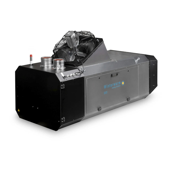
- Page 1 INSTALLATION MANUAL AIR HEATER TYPE DXC DXC - en - v2.0 / 11-2019...
-
Page 2: Table Of Contents
Contents 1 Introduction 8 Combustion settings 1.1 Symbols used in this manual 8.1 Adjusting the burner settings 1.2 Warranty 8.2 Converting to another gas type 2 Safety instructions 9 Troubleshooting 2.1 Installation 9.1 Volatile lock outs 2.2 Use 9.2 Temporary errors 2.3 Maintenance &... -
Page 3: Introduction
1 Introduction This manual is intended for the gas, electrical and mechanical installer. This document gives instructions on how to use and maintain the air heater. It is most important to follow the instructions in this document for safe operation of this air heater. -
Page 4: Safety Instructions
2 Safety instructions Always follow the safety instructions in this chapter when CAUTION! Always close the doors and inspection hatches installing, using or performing maintenance on this air of the air heater, except when adjusting and checking the heater: appliance. 2.1 Installation 2.3 Maintenance &... -
Page 5: Technical Specifications
3 Technical specifications 3.1 Performance Technical specification Unit Type DXC v4.1 DXC60 DXC80 DXC100 Net nominal heat input (max.) 65.5 83.0 Net nominal heat input (min.) 44.0 53.5 73.5 Heat output (max.) 59.9 75.9 99.1 Heat output (min.) 39.4 47.9 65.8 Efficiency at max. -
Page 6: Gas Types
3.2 Gas types 3.2.1 Natural gas G20 Specification Unit Natural gas G20 Nominal supply pressure mbar Supply pressure (min. - max.) mbar 17-25 Gas category P B/P NL: II DE: II BE: I E(s), I FR: II PL: II ELwLs Class B22, C12, C32 Specification... -
Page 7: Dimensions
3.2.3 Butane / LPG Specification Unit Butane / LPG G30 (B/P) Nominal supply pressure mbar 30-50 Supply pressure (min. - max.) mbar 25-50 Gas category P B/P NL: II DE: II BE: I FR: II PL: II ELwLs Class B22, C12, C32 Specification Unit DXC60... -
Page 8: Installation
4 Installation 4.1 Preparation • Make sure enough space remains to open the door of the air heater. Before installation, please use the data badge to check: • Make sure the wall can support the air heater. • Ensure sufficient clearance distance for the flue •... -
Page 9: Electrical Connection
NOTICE All gas supply lines must be mounted without any • When replacing this fuse, always use one of the mechanical tension. same type (5AT). NOTICE Always clean the inside of a gas supply line 4.5 Room thermostat before connecting it to the air heater. Place a gas filter in the supply line when needed. - Page 10 4.5.2 Bus communication system installation 4.5.3 Installation of multiple heaters on one control unit To connect the air heater to a bus communication system, do the following: An MTC or MTS room thermostat, or interface module can control up to 8 air heaters. To connect the air heaters, do 1.
- Page 11 1 2 3 4 5 6 7 8 1 2 3 4 5 6 7 8 1 2 3 4 5 6 7 8 Figure 9 - Positions of the S1 and J14 switches for the first three air heaters in a system NOTICE If the J14 switch of more than one air heater is set to the same number, the system will not work.
-
Page 12: Flue Systems
5 Flue systems To ensure safe and proper use, this air heater must be connected to a flue system. This flue system must be installed according to this manual as well as national and local regulations. A flue system consists of a flue terminal, piping and an optional condensate discharge system. -
Page 13: Flue Length (Max.)
5.1.1 Flue material 5.3.2 Air heater location Only use CE marked flue material from the manufacturers When an air heater burns frequently and is placed in Muelink & Grol (M&G) and Burgerhout. a normally heated room (temperature above 15 °C), condensate is unlikely to form. -
Page 14: Installation Of The Flue Terminal
Figure 14 - Condensate drain 5.4 Installation of the flue terminal CAUTION! Do not rotate the cap. There are flue terminals available for installation through a roof or through a wall. 4. Put the flue terminal into a vertical position. Use a level. - Page 15 5.4.2 Installation - Wall terminal 5.4.3.2 Elements system ALU FIX thick wall To install the flue terminal in a wall, do the following: An ALU FIX flue system is created with four elements (figure 15). 5.4.2.1 Preparation 1. Check all components for possible damage. 2.
-
Page 16: Operating The Air Heater
Requirements for horizontal and non-vertical piping: Every flue discharge system needs to be secured with at least one bracket. The first bracket needs to be within the • Maximum distance between brackets of 1 m. first 0,5 m of the air heater. •... -
Page 17: Minimum Firing Time
6.2 Minimum firing time 6.4.1 Heat exchanger The heater will always fire for a minimum of 1 minute, even An NTC sensor is located near (or on) the heat exchanger. if the heat demand stops. This is to avoid a large amount of This sensor monitors the heat exchanger temperature. -
Page 18: Combustion Settings
2. Instruct the end user about the operation of the 3. Press the (–) button until 0 is displayed to exit the heater: service. The air heater will always cool down the a. Lock-out indication heat exchanger for several minutes. b. -
Page 19: Converting To Another Gas Type
influence each other, always check both burner pressures at least twice after any adjustment. Low setting High setting High/Low Inlet Burner Figure 19 - Main parts of the gas valve DANGER! Always measure the air heater’s CO production. Too much CO usually means the gas mixture 7. -
Page 20: Troubleshooting
9 Troubleshooting 9.2 Temporary errors If the air heater malfunctions, first check if the problem is caused by external circumstances (e.g. no supply power). If the problem is not caused by external circumstances, The table below describes the temporary errors that can use the tables and instructions in this chapter to fix the air occur. -
Page 21: Instructions
9.4 Instructions Case 5: Too many flame failures while burning. After identifying the problem, use the Case number to find • The gas supply is not constant. This results in a the possible cause in this paragraph. drop in gas supply pressure while burning and causes the flame to extinguish. -
Page 22: Further Troubleshooting
Case 16: Flame detected before opening the gas valve. When the air heater does start but shows a different problem than described above, check if the following • Check if there really is a flame before ignition. If so: problems apply. Replace the gas valve. -
Page 23: Maintenance Of The Burner Unit
Some checks can only be performed when the heater is 1. Use compressed air or a soft brush to clean the running. Do the following: remaining parts from the air heater. Focus on the following parts: 1. Reconnect the air heater to the power supply. a. -
Page 24: Electrical Wiring Diagram
11 Electrical wiring diagram A complete electrical wiring diagram is shown in figure 20. The connections that are most important to the installation process are shown in figure 21. Connection type 21 (0-10V) Alarm output 230 V (optional) J9- 1 20 (GND) J9- 3 Bus communication system... -
Page 25: Exploded View And Spare Parts
12 Exploded view and spare parts The parts of the air heater are shown in an exploded view in figure 22. The table below describes each part and shows the correct article number for a replacement part. Figure 22 - Exploded view of the DXC60-100 Description DXC60 DXC80... -
Page 26: Declaration Of Conformity
13 Declaration of conformity Winterwarm Heating Solutions B.V. Industrieweg 8 7102 DZ, Winterswijk The Netherlands Declares that air heater types: • DXC60, DXC80 and DXC100 CE PIN: 0063BR3344 – Are in accordance with the essential requirements of the relevant EU directives, being: •... - Page 27 INSTALLATION MANUAL AIR HEATER TYPE DXC...
Need help?
Do you have a question about the DXC Series and is the answer not in the manual?
Questions and answers